Announcement

Collapse
No announcement yet.

Radiant Collector

Collapse
X
 
  • Filter
  • Time
  • Show
Clear All
new posts

  • Radiant Collector

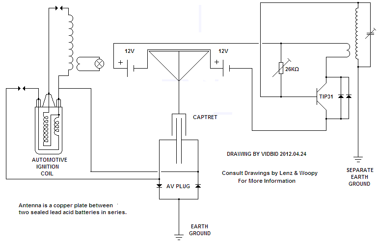
    One could say that there are two circuits at play here. The radiant collector and the radiant exciter.


    The radiant exciter has the purpose of radiantly exciting the batteries, of which there are two.


    The circuit is called a Brovin Kacher Radiant Exciter.

    The circuit for the radiant collector is called a Tesla Radiant Collector.


    Basic Schematic:


    The input to the radiant exciter circuit is about 20mA; however, the radiant collector is not directly connected to the batteries. Output from the radiant collector circuit can be seen to be considerably more than the input to the exciter circuit.

    More Detailed


    Replication #1
    HTML Code:
    http://youtu.be/2JxunfyhtFI


    Replication #2

    HTML Code:
    http://youtu.be/vnHTtpPvsTQ


    Replication #3

    Diodes for Replication #3
    Originally posted by kajunkreations View Post
    15kv 4 amp 100ns.
    HTML Code:
    http://youtu.be/nhbtOvNLnko
    These diodes cost about $30US each.
    Last edited by vidbid; 03-21-2016, 05:16 AM. Reason: Clarification
    Regards,

    VIDBID

  • #2
    Diode Recovery Times

    Originally posted by JohnStone View Post
    Sorry, I have to correct!
    The recovery time of a diode is in fact the switch delay time.

    - A 100ns diode will refuse any action at 10 MHz (conforms to 100ns full periode).

    - A diode is supposed to act in the half periode of an AC signal only. It will refuse therefore any action at 5 MHz (conforms to 100ns as half periode) as well.

    - Any recovery time obove 1/4 frequency periode shall be avoided - in any case!!!! So we have the absolute limit of 2.5 MHz for this 100ns diode. But this is not recommended at all. If we make use of this condition we have built an AC dimmer with phase control.

    - For estimation: I would suggest to convert the recovery time to frequency (1/x) and divide it by more than 8 (12 recommended). Then you have a viable operation frequency.
    Given: 100ns = 0.1µs => 10 MHz / 8....12 = 1.25 ..... 0.833 MHz.

    - For easy converting (1/x) in your mind regard: µs convert to MHz, ms convert to kHz. It is like calculation with volt and kOhm convert ot mA ......

    - You can get 20ns diodes being able to handle about 5 MHz but do not head for higher frequencies. You very probably will not get components within your financial limits - HV, high amp, supoer ultra fast......

    - For your better imagination see this diagram[/URL] and let the recovery time be less than Pi/4 (corresponds to factor 8 above).

    - Please do not hesitate to look in the data sheets. If you do not find a recovery time there then regard the diode to be built for mains frequency only!!!

    - Example: UF 5408 -> recovery time typical 75 ns @ 1A. If you apply max. current it will get slower. Same UF4007. So please calculate these diodes to have 100ns recovey time.

    Please regard the hints above. I want your setups to succeed. Any weak part of a chain detemines the max. load!
    rgds John
    Originally posted by dragon View Post
    I stand corrected...

    Thanks John, that clears the fuzzyness in my mind and a few questions I had in this area -
    Originally posted by zilano
    the aim of showing stealing electricity was just to make forum members and guests to understand that we need high frequency in tandem with high voltage to harvest more power using silicon fast acting diodes. and do the practical also for those who havent made slayer xciter circuit or mini or standard tesla coil.

    the experiment was basic step to understand frequency and voltage effects on charging cap.

    yes we r on same track tesla moray don smith and kapanadze.

    rgds

    zzzz

    Originally posted by JohnStone View Post
    Hi Zilano,
    thanks for your consecutive teaching! It refreshs the forum and oir minds again and again.

    I agree using fast diodes, as fast we can afford. In this sense the component mentioned before seems to be quite desirable.

    15STH06FP
    DIODE, HYPERFAST, 600V, 15A, TO220 Diode Configuration: Dual Bridge
    20ns @ 1A
    £1.12
    rgds John


    Interesting posts on this subject.
    Last edited by vidbid; 04-27-2012, 07:17 PM. Reason: Additional
    Regards,

    VIDBID

    Comment


    • #3
      On Kapanadze

      Originally posted by zilano


      well kapanadze used avramenko for initial start. the start device is triggered with diode free flyback trafo. the output of tesla coil is capacitored with one plate going to tesla hv and one to the rectifier ac point. the other ac point of rectifier was grounded. + and -ve then taken from bridge to drive inverting circuit. thats how kapanadze did it. u can do same way.

      post a bigger picture so i can decipher ur ciruit. more better.

      rgds

      zzzz
      I believe what Zilano is referring to when she says a "diode free flyback trafo" is a "diode-free flyback transformer." If that's what she means, well, I had no idea that some flybacks had diodes in them. I'll have to do some research on that.
      Last edited by vidbid; 04-27-2012, 08:09 PM.
      Regards,

      VIDBID

      Comment


      • #4
        On the Question of What is a Diode-Free Flyback Transformer

        Originally posted by zilano
        the color tv flybacks/monitor flybacks these days have inbuilt diode before hv terminal(black terminal).

        older tv flybacks that is early color models or black and white tv's have flybacks with no diodes attached before hv out. and these can be used for avramenko plug making. from ac hv terminal.

        rgds

        zzzz


        Image courtesy of Zilano
        Regards,

        VIDBID

        Comment


        • #5
          Originally posted by zilano
          Well Sergey!

          u can use the hv terminal of tesla coil to the outer enevelope of cap and charge cap with diodes from ground and then use use it to spark the trafo u can get hot electricity.

          polarization occurs using cap so use an inductor coil after the cap to make it unpolarized and then rectify it and use it to drive trafo.

          rgds

          zzzz
          So we need an updated schematic.
          Regards,

          VIDBID

          Comment


          • #6
            Originally posted by zilano
            well kapanadze used avramenko for initial start. the start device is triggered with diode free flyback trafo. the output of tesla coil is capacitored with one plate going to tesla hv and one to the rectifier ac point. the other ac point of rectifier was grounded. + and -ve then taken from bridge to drive inverting circuit. thats how kapanadze did it. u can do same way.

            post a bigger picture so i can decipher ur circuit. more better.


            the general circuit used to convert is below


            What about the transformer after the cap?

            And isn't there a spark gap in the Kapanadze design?
            Regards,

            VIDBID

            Comment


            • #7
              Kapanadze Patent

              http://www.tuks.nl/pdf/Reference_Mat...08103129A1.pdf
              Regards,

              VIDBID

              Comment


              • #8
                Directory contents of /pdf/Reference_Material/Donald_L_Smith/

                http://www.tuks.nl/pdf/Reference_Mat...an-16-2012.pdf

                Energy Products at Crystal Life Technology®, Inc.

                SLIM TOOLS

                caduceous coil experimental handbook and my experiments with it.

                Caduceus Coil Observations

                By Ken Wells 3/26/05
                Posted Under Category: Technology Articles

                Bookmark and Share

                courtesy of Ken Wells.

                --------------------------------------------------------------------

                * Yuggoth Investigations

                * Earthquake, Calif

                * `Live Long & Prosper'

                Caduceus Coil Observations

                --------------------------

                Background

                ----------

                The first mention of Caduceus coils we had heard was in the Cater

                book, `Awesome Life Force'. Cater here describes a `laser like

                pulsed beam of soft electrons' that is ejected from the coil, along

                with other bizarre effects such as levitation. Cater states this

                beam will radiate in a longitudinal pattern. A Vangard Sciences

                document describes other odd effects when testing Caduceus coils,

                namely space/time distortion and, again, levitation. Of course,

                given these interesting descriptions, it just had to be tested.

                The first tests were carried out rather unscientifically and most

                haphazardly. A make shift coil was built from 20 gauge insulated

                wire that used a 3" rachet extension as a core. Three windings or

                cross-overs were used. Pulsed DC at 9 volts was supplied to the coil

                at an unknown frequency. Three VAC was measured across the coil. The

                effects, however unconfirmable, are bizarre and worth mentioning to

                educate further investigators.

                The effects were: metal objects within a five foot radius became

                magnetized and the tester received a quite obvious skin burn.

                Needless to say, the negative effects were quite disturbing.

                The second experiment used a 14" iron bar with 19 windings. Pulsed

                DC was used again at approximately 12 volts at an unknown frequency.

                No burns or magnetism was experienced. The only effect which could

                be attributed to this experiment (although there are no direct

                linkages) was that the house became `charged'.

                The potential in relation to the human body had changed and now

                static shocks became annoyingly common. This effect lasted

                approximately three months and then dissipated to a normal level. No

                other unusual going ons were happening in the house at the time.

                Recent Experimentation & Results

                --------------------------------

                More recent and better controlled experiments with the Caduceus coil

                were recently completed. Every drawing of the coil we have seen

                Page 1


                contained only three windings, so that's where we began. The

                first test involved the following components:

                - 7 inch ferrite rod - 22 gauge magnetic wire

                - 8 volt 22,000 rpm motor - 6 volt battery supply

                - 9 volt battery - ELF Meter

                The magnetic wire was wound around the rod to produce three

                crossovers or nodal points along the core. The wire was then

                connected to the positive terminal of the 9 volt source and the

                pulse mechanism respectively.

                The pulse mechanism consisted of the motor output rotor pole rigged

                with a special circular fitting, half conductive, half non-

                conducting. The connection to the negative pole of the source was

                then broken and attached to copper poles which rested (with a slight

                tension) on the motor output rotor pole. This produced about 2000

                hertz, as measured by an oscilloscope. The waveform was distinctly

                spiked, as would be expected given the source.

                The ELF meter probe was placed approximately 7 feet from the rod and

                left at rest. The meter detects low frequency EMF in the 50 - 70

                hertz range, .001 milligauss to 50 gauss. Beginning readings on the

                ELF were 1.2 milligaus. The setting was a garage (late night) with

                the following mechanisms on: 150 watt and 60 watt lights, 1500 watt

                space heater.

                A compass was elevated and placed directly behind the coil to record

                any magnetic field disturbances. The looped end of the coil was

                placed facing to magnetic northwest. The coil was then energized.

                No immediate effects were noted. AC voltage measured through the

                coil was approximately .3 volts, much less than we expected.

                Within 5 minutes time, however, the ELF reading had dropped to .2

                milligauss. After eight minutes of time it decreased to .1, after

                twelve minutes it read a steady .0 milligaus.

                A noticeable decrease in the motor hum was noted after 13 minutes.

                After 15 minutes of operation the coil was de-energized. The

                following readings were logged after shutdown (nothing moved or

                touched):

                After 1 min = ELF .1

                5 min = .2

                10 min = .3

                15 min = .4

                20 min = .5

                25 min = .6

                The pattern repeated until the reading had returned to 1.2. Iron

                nails that had been placed around the coil showed no signs of

                magnetism.

                ************************************************** *****************

                An interesting psychic note: While the coil was in operation we did

                a walk through of the field (the strongest effects appeared to be

                within a 14 foot radius). One of the Yuggoth Investigators had

                recently been through a trip to England and had observed and felt

                the presence of ley lines, so the impression was still fresh in his

                mind. He reported feeling a strong ley line within 1 foot of the

                looped end of the coil. The line orientation was approximately

                north-south.

                Page 2


                ************************************************** ***************

                To verify the dissipation of 60 cycle and harmonic EMF was linked

                to coil operation and not a property of the 22,000 RPM motor, the

                coil was disconnected and the motor ran for a equal amount of time.

                No effect on the ELF meter was observed. This appeared to confirm

                the fact that this dissipation effect was a property of the Caduceus

                coil. This raised many puzzling questions. Could 60 hertz

                (appliance) radiated EMF be canceled by the use of a properly tuned

                Caduceus Coil?

                Why had neither of the effects noted in previous experiments been

                observed? What element had been key to the 60 hertz effect - wire

                turns, input frequency, orientation, voltage or a combination of

                all? We decided it was time to get serious. Since no other

                documentation existed on the Caduceus coil, we figured it was time

                to write some.

                The following equipment was secured in order to put this thing

                through it's paces: - HP Signal Generator (1-990 MHZ)

                - HP Frequency Counter

                - Tektronics Oscope

                - HP Function Generator

                Our thinking was:

                1) We had to have much better control over the input source

                2) Needed a wider range of input freq/voltages

                3) Needed to establish better testing of effect & coil

                properties while energized

                4) Devise some type of canary (as a means of sensing hazards)

                5) Begin all over to answer the questions listed above

                Number 4 came about because of a Yuggoth Investigator's brother who

                had stopped work to eat lunch. He didn't realize he was perched in

                front of a microwave dish until he began to feel a bit hot (powers

                of observation not withstanding).

                The point was well taken, but beyond the ELF, Compass, common sense

                and the body's ability to quickly transmit pain, we knew of no other

                way to protect the lily white of our rears.

                One interesting idea we had for measurement is connecting the ELF

                meter, or alternatively a large wrap of magnetic wire, and use the

                scope to monitor wave changes and increase the frequency range

                available to us.

                Frequency sweeping of the Caduceus coil is currently underway. All

                progress will be made available as documented. We expect completion

                by March.

                * Yuggoth Investigations

                * Earthquake, Calif

                * `Never Leave a Corpse'
                Mobius Coils
                Last edited by vidbid; 05-01-2012, 04:45 AM. Reason: because I felt like it
                Regards,

                VIDBID

                Comment


                • #9
                  Originally posted by zilano View Post


                  warning: copper antenna rod must be insulated not to touch any coils. one has to use a high inductor(variable) between copper antenna and the feed to avramenko plug to charge battery.(not shown in the above pic)
                  if one finds that battery is not charging optimally then one can add more 4700mfd/12 v caps in parallel or vary the inductance acting as resistance for hv+hf ac.whichever suits best.
                  I thought I would post this here. You never know.

                  Attached Files
                  Regards,

                  VIDBID

                  Comment


                  • #10
                    Donald L Smith Inventors Weekend 2001

                    This is just a test.

                    To download the video file as a MP4

                    I suggest you download and archive yourself a copy before it is removed.

                    You know how these things go.

                    Video can be seen at Donald L Smith Inventors Weekend 2001 - YouTube

                    KeepVid: Download and save any video from Youtube, Dailymotion, Metacafe, iFilm and more!

                    Or you can buy a copy at ebay (current bid at $23) at Don Smith DVD (free energy) - Strange video | eBay
                    Last edited by vidbid; 05-01-2012, 03:45 PM. Reason: because I felt like it
                    Regards,

                    VIDBID

                    Comment


                    • #11
                      Originally posted by Ganzha View Post
                      Hi! I am sorry - I am new here, but plug Avramenko in this case shoud be double!

                      Attached Image:


                      Originally posted by zilano View Post
                      this will work also and single also as there is resonance between primary and bifilar(bucking secondary) and earth ground. all 3 are in resonance.

                      zzzz


                      Originally posted by Garsony View Post
                      Hi Zilano,
                      Can you express your understanding of hot to cold conversion method, using iron or ferrite core transformer (without inverter)? Thank you.


                      Originally posted by zilano View Post
                      well the system you quoted is also working system but for that we have to choose the right capacitor to work with frequency of 50/60 hz without needing invertor. this setup is for those who understand frequency nomographs and how to calculate frequency and capacitance etc.

                      for novices and new learners the easiest path is the right way. the simplest and easy circuit with two transistors for 50 hz/60 hz is below.

                      you can find various circuits for invertor making according to your country grid voltage like 120 v/60 hz 230v/50 hz etc or the rather best option is to use readymade invertor.

                      always measure output voltage before attaching invertor. the voltage must be 12/24 volt. usually its 12 volt for 800va that is somewhat 720-760 watts. 24 volts is for 1500 va. voltage is critical. if voltage fed is not proper for the rated invertor /inverting circuit it can fry ur invertor or inverting circuit.


                      zzzz

                      Attached Image


                      Originally posted by zilano View Post

                      Originally posted by Garsony View Post
                      May be I don’t understand something here…. ???
                      In this method we are pulsing primary of iron core trafo with 50/60 Hz, the same way as tesla air core coil. This is the resonant transformer.
                      By using this method we have to match frequency of secondary coil with primary and we will get 50/60 HZ cold electricity at output of iron core transformer again.
                      Originally posted by Garsony View Post
                      Looks to me the 50/60 Hz modulation is needed.
                      resonance happens when two coils have same frequency or harmonic. the output trafo primary resonates 50/60 hz but output secondary doesnt. it just gets same frequency induced by induction and its not air core.

                      when pulsed dc is used to feed primary the secondary gets induced ac of same frequency.

                      zzzz


                      Originally posted by zilano View Post

                      Originally posted by boguslaw View Post
                      That's what bother me all the time. I'm still not good in electronic and don't know where to place capacitors in such inverter schematic I know they should be here parallel to primary coils and they should be turned on/off sequentially because that is how this circuit works I think (push-pull ?).

                      try to learn more about induction coils. u will see how pulsed dc is used to induce ac in secondary coil.

                      2nd thing is when pulsed dc is fed in parallel Lc combination it oscillates at its Lc frequency. understand below


                      zzzz

                      Attached Image:


                      Originally posted by Garsony View Post

                      Originally posted by zilano View Post
                      resonance happens when two coils have same frequency or harmonic. the output trafo primary resonates 50/60 hz but output secondary doesnt. it just gets same frequency induced by induction and its not air core.
                      So, the primary of iron core trafo must be center tap (bifilar) like kajun kreations said. is it correct?


                      Originally posted by zilano View Post

                      Originally posted by Garsony View Post
                      So, the primary of iron core trafo must be center tap (bifilar) like kajun kreations said. is it correct?
                      not necessary. but if u use invertor circuit then 3 tap winding is required.

                      zzzz


                      Originally posted by zilano View Post

                      Originally posted by Garsony View Post
                      I tried 600-230v iron core transformer by using this setup, it didn't work for me. Still thinking why.
                      coz u tried iron cored for rf. try ferrite core or toroid. if u had rectified and then used dc then u can use iron cored trafo.

                      zzzz


                      Thanks for the information on the technology.
                      Last edited by vidbid; 05-01-2012, 08:01 PM. Reason: Clarification
                      Regards,

                      VIDBID

                      Comment


                      • #12
                        woopy spark gap thingy

                        In the woopy video, "charging by induction", at 2:52 he shows a little spark gap he is using. I couldn't understand what he said....what is that little thing...I want one.

                        Orion

                        Comment


                        • #13
                          It's a gas discharge tube. Basically a sealed preset spark gap. Mouser or Digikey sells various voltage ratings.

                          Comment


                          • #14
                            Originally posted by dragon View Post
                            It's a gas discharge tube. Basically a sealed preset spark gap. Mouser or Digikey sells various voltage ratings.

                            awesome, much thanks

                            Orion

                            Comment


                            • #15
                              Charging by Induction

                              FYI Only - the Charging by Induction thread dovetails into this thread rather nicely.

                              Essentially, from what I can tell, the Radiant Collector is charging by induction.

                              Best regards,

                              Berg

                              Comment

                              Working...
                              X