Announcement

Collapse
No announcement yet.

Use for the Tesla Switch

Collapse
X
 
  • Filter
  • Time
  • Show
Clear All
new posts

  • Tesla Switch

    Matthew, "I'm Not yelling Here"
    Look it is real simple if two batteries go into series minus the junction drop most of the heat will be in the transistor. This circuit works like a current charge pump. This is all about switching and how the switch works. The Tesla Switch is nothing more then a dual charger of which you can take energy from. You all must understand I do not like to use the term current because this is just the dissipation of the potential in the system which is the voltage. You want to use the least amount of current to charge the batteries, the batteries understand what the signal is since your scope can not see it. What you will notice is a sharp funny looking square wave, not what I have seen so far, I will try to take pictures for you all. The minimum scope must be at least 100Mhz to see anything. I was showing Peter yesterday when you get it switching right you will see the scope go negative 1 1/2 times the input, This would give you a COP of 2 anymore then this, John would not be around to talk about anything. I will try to draw it for you. The 50% duty cycle will do this, and you can run this down to 10% if you want. Try just building this simple at first so you can see what is going on. Timing is not the key the switch is and the device used. Right Leroy Good Job.
    JB
    Last edited by John_Bedini; 11-20-2010, 04:59 PM.
    John Bedini
    www.johnbedini.net

    Comment


    • simple

      Yes John B
      Simple,that is the way to start --it's the way to
      replicate
      Kevin


      Originally posted by John_Bedini View Post
      Ok,
      I guess I should go over this again. The first thing I said to everybody is the three battery test was to show which way the potential goes.... I set up the three batteries with biased transistors, just two, the third you could switch so you could see what was going on in the circuit. I guess we find two things going on one with the four battery system and the other the Scalar charger. Both the circuits do the same thing one doubles the voltage and slams it back to the battery(Scalar Charger) but it is more then that as this one is a current charge pump. That pump drives things negative. The four battery system does the same thing but it does it buy putting the batteries in series then it slams the current across the paralleled load. This is very simple to do with two transistors and some diodes. The first part of this is how much potential can you move in a micro second before the current builds up in the circuit? Look at the drawing and see if you can see how you get the power out!!! I will be busy but I will check back.
      John B
      Last edited by redcar1957; 12-11-2009, 01:52 PM.

      Comment


      • JB said@" You all must understand I do not like to use the term current because this is just the dissipation of the potential in the system which is the voltage."
        I understand now. Your not saying amperage can't run across the load. Your saying because there is no ground we are driving from voltage only.

        I was understanding previous statements to mean we were not to measure amperage at all. IE switch fast enough that the amperage does not appear. (11+ khz).

        Well I already have at least 6 switch's that probably just need the load adjusted and they will work. I have built 14 of these things. I would hope I was somewhat familiar after that many. Although I haven't seen charging I have seen some pretty miraculous run times.
        I'll start looking for that wave.

        Thanks Again John
        Matt

        Comment


        • [QUOTE=ldissing;77321
          What bulbs does JB have in his little test board. They are 3.2 to 3.8 V 20ma high intensity diodes. Ah, less than 4V.
          Leroy[/QUOTE]

          Leroy
          A led is another diode inline and the flow will be in only one direction. Don`t we need a resistive load there like a 3v torch bulb?
          Last edited by nvisser; 12-11-2009, 05:38 AM.

          Comment


          • I think we need a DC motor as a load?
            Or a BLDC off a "FWBR-ed" capacitor?
            expect 6...8V off the 12V battery system =75% of potential in one side mode (other side shorted)
            Or about 50% of potential from both sides (alternating)

            Br. Bedini, kind thanks for "spilling the beans":

            I did wonder how come -mechanical- switch from Electrodyne compete with PWM if duty cycle was <> 50%

            I need just time now to make a decent build

            Comment


            • Originally posted by ldissing View Post
              @Matt

              series batteries - diode drops (~18V if batteries are at 12V) - potential across the light must be >= parallel battery voltage + 2.

              Series (Vs ) - 6 (Vd) - potential across light (Vl) = parallel(Vp) + 2

              Solve the equation

              Vs - Vp - 8 = Vl (max potential drop across the load)

              Matt, I believe that he is saying that the light will have a potential drop across it. You can NOT have a 12V bulb in there, you can't have a 9V bulb in there, you can not have a 6V bulb in there. You have to have a 4 volt or less bulb in there, to get at least 14V (2V over the battery voltage) to get the battery to charge. You can run a load at a higher potential, but do not expect the batteries to charge.

              You do not need current, just potential. So, your load can not have a big potential drop. What bulbs does JB have in his little test board. They are 3.2 to 3.8 V 20ma high intensity diodes. Ah, less than 4V.

              If you want to get power out of the system, then just hook the load up to the batteries, or run it at a 50% duty cycle (with the 3524, just disconnect the resistor to ground from pin 2, i.e. no additional delay) and it will run longer than it would on the 4 batteries alone.

              Leroy
              In other words:

              1. Just pick one battery on that switch
              2. hook a load to it
              3. drain it with that load while running the switch on it.
              4. Report back (would be nice) ;-)

              OR

              1. pick a low Ohm & low volt load (say a parallel LED array?)
              2. put it in the path of charge in the TS (there are six (6!)) to do this
              3. Have it do work while just topping off the batteries
              4. report back

              All with:
              A. 49.9 % D/C (=duty cycle)
              B. 33%
              C. 25%
              D. 10%
              E. 1%
              F. 0.1%

              IMHO that would be nice spreadsheet
              ;-)

              @ Lero


              You are a genius mate!

              Comment


              • How about a 8 battery switch (the SCR config) with switching from 4 parallel to 4 series?
                no?
                would provide "tons" of volts?

                Comment


                • Originally posted by StevanC View Post
                  How about a 8 battery switch (the SCR config) with switching from 4 parallel to 4 series?
                  no?
                  would provide "tons" of volts?
                  Go slow my friend, build a good foundation first.

                  Bit's

                  Comment


                  • for wave form

                    Thank you John.B for kind advices.

                    Could I ask at which point I could get the correct wave?

                    I built the full swithcing circuit with two TRs you suggested and failed to
                    work it on full swithcing.
                    It worked well on one-side switching with only half circuit but not with full circuit.
                    I also tried the 6-TRs switching running well on full switching.
                    I will do my best to follow up your guides and concentrate on this list
                    with stopping my running project on the Kromrey Converter.
                    You say it easy, but not easy for me to understand. Let me go aghead.

                    Regards,

                    JANG

                    Originally posted by John_Bedini View Post
                    Matthew, "I'm Not yelling Here"
                    Look it is real simple if two batteries go into series minus the junction drop most of the heat will be in the transistor. This circuit works like a current charge pump. This is all about switching and how the switch works. The Tesla Switch is nothing more then a dual charger of which you can take energy from. You all must understand I do not like to use the term current because this is just the dissipation of the potential in the system which is the voltage. You want to use the least amount of current to charge the batteries, the batteries understand what the signal is since your scope can not see it. What you will notice is a sharp funny looking square wave, not what I have seen so far, I will try to take pictures for you all. The minimum scope must be at least 100Mhz to see anything. I was showing Peter yesterday when you get it switching right you will see the scope go negative 1 1/2 times the input, This would give you a COP of 2 anymore then this, John would not be around to talk about anything. I will try to draw it for you. The 50% duty cycle will do this, and you can run this down to 10% if you want. Try just building this simple at first so you can see what is going on. Timing is not the key the switch is and the device used. Right Leroy Good Job.
                    JB
                    Last edited by JANGYD; 12-11-2009, 12:55 PM. Reason: change the line

                    Comment


                    • Originally posted by Bit's-n-Bytes View Post
                      Go slow my friend, build a good foundation first.

                      Bit's
                      sorry,

                      I guess this goes to my "what do we do next" basket until I get that "Vanilla Tesla Switch" report done


                      Stevan C.

                      P.S.
                      Anyhow a 16Diode 4BJT 4opto project would be "no rocket science" once we figure this?
                      Last edited by StevanC; 12-11-2009, 01:04 PM. Reason: typo agrrrh! :(

                      Comment


                      • Originally posted by StevanC View Post
                        In other words:

                        1. Just pick one battery on that switch
                        2. hook a load to it
                        3. drain it with that load while running the switch on it.
                        4. Report back (would be nice) ;-)

                        OR

                        1. pick a low Ohm & low volt load (say a parallel LED array?)
                        2. put it in the path of charge in the TS (there are six (6!)) to do this
                        3. Have it do work while just topping off the batteries
                        4. report back

                        @ Lero


                        You are a genius mate!
                        I wish I was a genius. JB told us in the beginning, that you had to have some potential left, he didn't say you needed 2 volts, but he did indicate the 18V - load potential...and you needed some left over. That is why I started with the 3.2 V - 3.8V high intensity led after looking over JBs photos...just a hack and a copycat! BTW, I did have some really good results with that led. Tried to go up to 6V, did get some charging with that too, but I did not have 2V drop over all my parts.

                        You can NOT run a load off one of the batteries and have it in the switch charging it simultaneously. JB has always said that was a no no. You can parallel the batteries and run a bigger load, i.e. a 12V load or run a 6V load while running the TS and it will run for a very long time. Or, you could have 4 batteries, using one for the bigger load, and use the other three in the 3 battery switch until all are charged. Take the one that WAS running the load, and put it in the 3 battery switch and take one of the charged batteries and let it run the load. Keep that going and you have continuous power.

                        Lero to you my friend.

                        Comment


                        • Originally posted by nvisser View Post
                          Leroy
                          A led is another diode inline and the flow will be in only one direction. Don`t we need a resistive load there like a 3v torch bulb?
                          Well, JB was using 2 loads (on that little circuit board), so that each load had the potential across the load in the correct direction. I'd have to think about it a little, because I was having some issues (in my head) with hooking that up properly with a single load. I did also use a double bridge with only one load and that worked for me too, but then you lose some of the potential across the bridge rectifiers.

                          JB said that in AC mode, you do not have charging. Look at the places in the circuit where the load was connected. It isn't across the AC (neg to neg). It was out the two diodes to the neg of the 24V side and the same for the other side. Two different virtual positives, two different negatives.


                          Leroy
                          Last edited by ldissing; 12-11-2009, 03:04 PM.

                          Comment


                          • Batteries

                            Originally posted by Bit's-n-Bytes View Post
                            Go slow my friend, build a good foundation first.

                            Bit's
                            Slow is good. JB said he was going to build a big switch...do not know exactly what that means, but you need a BIGGER switch to do what I'm going to suggest below.


                            Or, just use 24V batteries in the first place.
                            48 - 6 - 24 = 18V potential.

                            18V batteries
                            36 - 6 - 18 = 12V potential.

                            So, use 12 6V batteries - 3 6V batteries in series, all hooked together as one battery * 4 to get 12V potential out. Run your inverter on that for a while. You will not get a lot of charging out of it, but it should run for a long time. If you want to get some charging out of it and use it too, use 20V batteries. 10 2V in series = 40 batteries.

                            I think about this stuff a lot. I use about 58-60 kW a month. So each day, it is about 2 KW. How much energy does the system have to produce to give me 2KW a day if I run it 24 hours a day. Seems like to me, if I can produce 100 W an hour, in 24 hours, I've produced more than I use 100W an hour is roughly 10 amps at 12V, or 1 amp at 120V. With net metering, I can keep that darn meter from moving into the positive with only 10 amps continuous from a 12V system. If I'm wrong, and it is 2.4 KW / hour / day, then I'd have to produce quite a lot more, like 20 times more or 200 amps at 12V or 20 amps at 120V.

                            Leroy
                            Last edited by ldissing; 12-11-2009, 03:49 PM.

                            Comment


                            • I think about this stuff a lot. I use about 58-60 kW a month
                              I don't see any reason (outside of the basic understanding) why you couldn't setup a 120 volt system. 11x 12 volt batteries on each side. Run it at 60 hertz.
                              It would probably power a conventional 110 load. At least a motor or lights. I am not sure how anything else would act off of it.

                              Thats still pretty far ahead from where any of us need to be though.

                              I am happy it really doesn't have to go that fast. I am pretty sure looking at whats running I have had a functional switch for some time. I was just going to fast.

                              Cheers
                              Matt

                              Comment


                              • Hello Everyone.
                                Since this is my first post, I apologize for the length, but I felt it necessary to bring everyone up to speed on what I had going on.
                                I would like to take the opportunity to commend everyone on their most excellent input and hard work on the Tesla Switch. This device intrigued me when I first heard about by reading a PDF floating around the Internet.
                                The PDF can be found @: http://www.freeenergynews.com/Direct...itch_PGFED.pdf

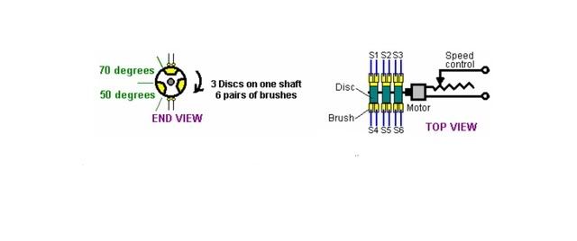
                                Since my field of expertise lies in the mechanical, about all I can do is mimic what other people have done when it comes to the electrical side of this device. I decided to build a mechanical version anyway and do a few experiments myself, just to see if this device actually did what people claimed it to do.

                                The switch I built was based on the abstract drawing on page 6 of the above PDF and is shown below. I think all of you have seen it. It has a 20 degree OFF TIME in between switching the batteries from the parallel to the series state. I have constructed the commutator in such a way, that it is possible for me to adjust the OFF TIME to zero by increasing the width of my carbon brush. Right now it is set like the drawing. From what I am reading on this forum though, the OFF TIME may be set to high the way it is now. The switch is capable of running @ 500 Hz if I have it figured correctly. It switches from parallel to series 3 times per revolution and I have a 10,000 RPM motor driving the thing. Someone fell free to correct me if I am wrong on these calculations. The brush holder was constructed in such a way so one could attempt to to harvest energy spikes from the “spark gap” with a collector coil of sorts. But that experiment is in the future.


                                For my first series of experiments, I have decided to take the motor that drives the switch completely out of the loop and just drive it from the grid. In this way I won’t be chasing ghosts troubleshooting the system. Once the device is functioning properly, I will work on obtaining or building some sort of motor that will run off the bridge to drive the switch. It is my understanding, that the back EMF of conventional motors kill the spike that is needed for this thing to work.
                                My purpose in building this switch was to assemble a device that would perform some sort of actual work. The unit is rather large and uses 4 car batteries. (I found out later I may need to replace them with deep cycle but I am hoping these will work for the initial experiments) Right now I will just use light bulbs to drive the load. Something tells me I need something other than 12 volt bulbs though.

                                Construction, which started early this year, is complete and the testing phase has begun. 1000 mf caps were used in the first run attempt as shown in the original schematic found in the PDF from FreeEnergy. However the device failed to produce any significant voltage across the bridge. After examining a wiring diagram provided by Mathew Jones on the Panacea site and reading about his success on this Forum, I acquired four 1 farad car stereo caps and hooked them in series as per his schematic. A meter across the across the bridge now yields about 3 volts @ 2000 RPM… so that is somewhere around 100 HZ I am guessing…I am unsure whether or not the little circuit board on top of the caps is causing any problems. After charging the caps, they bleed down to about 3 volts when the machine is started. One of them goes negative …not sure what that is all about yet. I have pic’s of this monster, but fear if I post them I will be laughed off the Forum for all the over engineering that went into the thing, … but I am having a good time and continue to learn.…and that is a good thing, right?

                                I have also acquired an oscilloscope that I plan to learn how to use. I am somewhat reluctant to jump right in without some instruction on where to hook up the scope so I can keep an eye out for the spike and square pulse needed. (I don’t want to fry my new toy) Any input in this area would be greatly appreciated and help me to speed up my experiments.

                                Soon to be built, is a different type commutator switch that will operate from 0 to 500 HZ and will spin under 1000 RPM. Thus reducing any “floating” that may occur in this type of application and will require less power to run. But as far as I can tell, I get good contact across the switch points even at 10k RPM with the one I have now(as mentioned earlier the sweet spot is around 2k RPM), it is just not very efficient as it requires about 1/3 HP to run. The newer switch design should require about 1/35 HP.

                                This project promises to be quite entertaining and I have decided if nothing else, it will be my contribution to America’s financial crisis, by putting money back into the economy…

                                Thank you all for your time and I hope in the future I will be able make a useful contribution to this “Work in Progress”, given my limited experience in this particular field.

                                Regards,
                                Murlin

                                Comment

                                Working...
                                X