I would like to start little thread to help us replicate at least one circuit close to overunity or maybe self-running. You all know how important it is , even just 1W without obvious power source....
Announcement
Collapse
No announcement yet.
Delamorto simple inverter device
Collapse
X
-
-
I have problem locating 30mf capacitor. I found 30uF 450V capacitor but I'm quite unsure if this is usable . I have been told there are two kinds of such AC capacitors : run capacitors which are connected to the Ac motor and add a torque at correct moments and startup capacitor which add initial kick to the motor to avoid initial raised current draw (from power grid) issue. I'm not familiar with AC capacitors for motors and cannot differentiate them while most sellers I asked have the same trouble
Anybody can help to find proper AC capacitor for this circuit ?
Another issue is to convert schematic of inverter from Russian elements to international : I found that CD4017 most probably is the same as Russian K56IE8 chip in schematic but as I cannot find K56IE8 datasheet I cannot match terminals of both
Need help from our Russian fellows - please locate K56IE8 datasheet and compare to CD4017 , without this we cannot replicate this circuit.
Comment
-
Ok, I did some research and found that at probability 99% K561IE8 is a counter chip which replacement is CD4017 and terminals seems to be the same if my Russian language don't fool me (it's rather limited)
KP723A mosfets used are 60V 35A nice ones with very load resistance 28mohm.
Replacement would be IRFZ44 I suppose.
Comment
-
-
This inverter uses vacuum tubes? Heater filaments in tubes take a lot of current and that would seem to limit OU possibilities although I know there are references to other devices being OU with tubes (primarily Telsa's car and the SM TPU although SM never appeared to use tubes himself). Do you have any more English references on Delmarto's device?There is no important work, there are only a series of moments to demonstrate your mastery and impeccability. Quote from Almine
Comment
-
No vacuum tubes at all. Here is his (delamorto) post
Selfrunning Free Energy devices up to 5 KW from Tariel Kapanadze
Comment
-
Hi Boguslaw, That device requires some parts I don't have either. I would need
to make the 600 mH inductor and buy the 30 mF capacitor. Is the 70 watt
inverter a bought one or made ? The circuit itself is a load, recovery and supply
circuit the inverter though is a whole other circuit.
Is there a video of this arrangement running ?
Cheers
Comment
-
That makes more sense. However the circuit in your post above shows two vacuum tubes - VT1 and VT2 and the diagrams are of vacuum tubes. What circuit does that relate to? (attached below)Originally posted by boguslaw View PostNo vacuum tubes at all. Here is his (delamorto) post
Selfrunning Free Energy devices up to 5 KW from Tariel KapanadzeAttached FilesLast edited by ewizard; 05-02-2012, 03:52 AM.There is no important work, there are only a series of moments to demonstrate your mastery and impeccability. Quote from Almine
Comment
-
VT1 and VT2 are Russian N-chanel mosfets. International replacement would be IRFZ44 or better IRFZ48Originally posted by ewizard View PostThat makes more sense. However the circuit in your post above shows two vacuum tubes - VT1 and VT2 and the diagrams are of vacuum tubes. What circuit does that relate to? (attached below)
Comment
-
Inverter is made and schematic is in one of my posts above however using Russian electronic chips. We need a little help to replace them. The essence I see in schematic is usage of counter divider chip to chopper output signal of normal CD4047 based push-pull inverter. I may be wrong because my electronic knowledge is limited.Originally posted by Farmhand View PostHi Boguslaw, That device requires some parts I don't have either. I would need
to make the 600 mH inductor and buy the 30 mF capacitor. Is the 70 watt
inverter a bought one or made ? The circuit itself is a load, recovery and supply
circuit the inverter though is a whole other circuit.
Is there a video of this arrangement running ?
Cheers
Comment
-
Thanks, sure looked like a Vacuum Tube symbol of sorts and I guess you could say the VT had me thinking Vacuum Tube.Originally posted by boguslaw View PostVT1 and VT2 are Russian N-chanel mosfets. International replacement would be IRFZ44 or better IRFZ48 There is no important work, there are only a series of moments to demonstrate your mastery and impeccability. Quote from Almine
Comment
-
Hi all
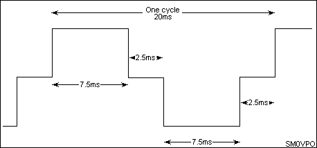
I think the key is the waveform, is not a square wave,outputs 0 and 5 are to insert in each half-cycle time off.
If there is no replacement for K561, you can use any simple oscillator clock input of 4017. The frequency will be x10 (10 steps one cycle)
I'm collecting the components ...
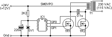
Another interesting option might be this:


PIC based DC/AC Mk-II
PIC based DC/AC 01 by SM0VPO
PIC based DC/AC Mk-III
 Last edited by torpex; 05-03-2012, 08:55 AM.
Comment
Comment