 Tweet
Tweet
Hi all, This thread is for all different kinds of motor/generator modification's.
I know there is already a lot of other motor generator threads but I thought a
thread with some devices developed from existing common equipment or
household appliances might be fun.
To show my first bit of progress toward exploring this area of experiment I
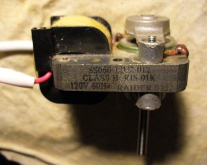
present the "Generating Field DC Motor". I used a vacuum cleaner motor which
I think was a 2000 watt rated vacuum. I believe it's a universal motor I tested
it with 120v AC first as it was originally wired with the armature in series with
the field coils, and it went well with 50 watts.
Generating Field DC Motor 24v input - YouTube
Generating Field DC Motor - YouTube

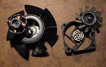
Then I separated the armature and the field coils and inserted another coil
between the field coils to make the two field coils in series with the other coil
then by powering the armature with DC from a battery the motor works and I
can get power out of the field coils as well.
Being out of an abused vacuum cleaner it's not as efficient as it could be
it seems to work well from 24 volts and has quite a bit of power. I'm
interested at looking into using some common appliance parts/motors to
experiment with.
I was also thinking about trying to use it the other way around by using a
motor controller to pulse the field coils then take the power from the armature.

I know there is already a lot of other motor generator threads but I thought a
thread with some devices developed from existing common equipment or
household appliances might be fun.
To show my first bit of progress toward exploring this area of experiment I
present the "Generating Field DC Motor". I used a vacuum cleaner motor which
I think was a 2000 watt rated vacuum. I believe it's a universal motor I tested
it with 120v AC first as it was originally wired with the armature in series with
the field coils, and it went well with 50 watts.
Generating Field DC Motor 24v input - YouTube
Generating Field DC Motor - YouTube
Then I separated the armature and the field coils and inserted another coil
between the field coils to make the two field coils in series with the other coil
then by powering the armature with DC from a battery the motor works and I
can get power out of the field coils as well.
Being out of an abused vacuum cleaner it's not as efficient as it could be
it seems to work well from 24 volts and has quite a bit of power. I'm
interested at looking into using some common appliance parts/motors to
experiment with.
I was also thinking about trying to use it the other way around by using a
motor controller to pulse the field coils then take the power from the armature.


 I can be


 I'll show more clearly the wiring and stuff
Comment