Announcement

Collapse
No announcement yet.

Modifying Motors/Generators

Collapse
X
 
  • Filter
  • Time
  • Show
Clear All
new posts

  • #16
    Originally posted by geotron View Post
    Would there be any change in performance through pulsing the armature with
    a capacitor instead of connecting it to the battery? With a second capacitor
    on a CDI circuit in series with the emitter of the armature coil, it seems
    like it would collect the emf output of the coil and could then be used alternately
    to for some purpose during the off pulse of the motor.
    Yes, because we then get inductive kickback which also contributes to the motor torque. This is, I believe, one of the keys to three overunity devices I have been studying but not only cap discharge to the coil, we need the coil to discharge to a cap. The energy then stored in the cap can then be used to power a load or be used to power the motor again with maybe a small top up from the source. The energy transfer from cap to coil to cap is more efficient.


    Originally posted by geotron View Post
    Through the use of another coil in series with the other three, could it possibly
    obtain a suitably higher voltage with which to charge a 12V battery?

    [ Fan Rotor Generator, 4.7uF ]
    What we need in our motor coils is amps, in this case, induced amps. Obviously under ohms law we want low resistance to give maximum torque. when we collect power from the coils it will introduce an impedance which fights against this but with the use of a transformer any draw lowers the impedance of the transformer. Hopefully there will be enough variance in the voltage of the field coils to make the use of a transformer a good option for energy collection.

    Comment


    • #17
      Unfortunately I don't think it will do much good measuring much with particular
      motor, the bearings are shot. It's stiff to turn again, i'll have to find another one
      tomorrow, I did disassemble a food processor but it's motor has brass bearings
      and a multi tapped field with much thinner wire, I noticed it has a big diode with
      a heat sink wrapped around it and DC will make it run.

      So my bearing would be causing a lot of drag, they stayed ok for a while
      after I freed them up but now they are even making funny noises, obviously
      worn out. I've got other motors but they're bigger.

      Cheers

      Comment


      • #18
        You need to find a large power tool as they have up to 2Kw motors. I am using one out of a 2Kw cut off saw and a 1.2kw angle grinder. As I am using lower power in them, I have to reduce the contact pressure of the brushes but I can get them to run off 12v no problem.

        Obviously the high power units have lower resistance coils

        Comment


        • #19
          Well this motor has skate board wheel bearings so I ordered some new
          ones, there are single skate board wheels on ebay for less than $7.00 Aus.
          They're 608 bearings - 22x8x8 mm or thereabouts. I managed to reduce the
          brush pressure a bit too.

          Comment


          • #20
            In regards to the output voltage of this fan motor, it looks as
            though from pulsing it with two AA batteries that it will produce
            around 9V at ~4hz. It may be that it will instead have to be
            stepped down eventually when running on its own.

            Originally posted by mbrownn View Post
            What we need in our motor coils is amps, in this case, induced amps. Obviously under ohms law we want low resistance to give maximum torque. when we collect power from the coils it will introduce an impedance which fights against this but with the use of a transformer any draw lowers the impedance of the transformer. Hopefully there will be enough variance in the voltage of the field coils to make the use of a transformer a good option for energy collection.
            Collecting energy into a load is one of the areas I purport could stand a few
            improvements. The concept I've been working with is, through utilization of an
            input switch that is normally 'on', energy would be gathered into a reactive medium
            such as that of a capacitor. The output of this capacitor would be on another
            switch normally off and the two would oscillate back and forth between charging
            and discharging the capacitor from the source into the fan motor.

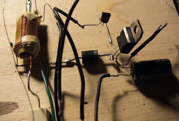
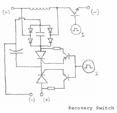
            The resonator shown here will produce around 75V on a 22uF from 12V input without the
            switch present, then dropping to 45-50V with it connected, and subsequently dropping
            to 35V or so when the gate is connected to a small signal npn transistor.

            Hopefully there exists some merit to this technique... and perhaps a better way
            or combination of parts that would gather energy at greater level.

            Comment


            • #21
              With a coil, no current is consumed in the making of a magnetic field, any Current that enters a coil, comes out the other side. The key things in calculating the magnetic force in a coil is ampere turns, the only voltage required is what is required under ohms law to make that current flow. We know that the energy lost in a wire is again related to ohms law. This means that resistance is a loss and serves no other meaningful function therefore it should be eliminated as much as possible. This way, less power is consumed in a motor.

              Other losses are friction and iron losses and we all know to reduce friction as much as possible. so lets talk about iron losses. Eddy currents are a type of transformer action that consumes power and we reduce this by lamination of the iron or using special composites. This now leaves the power lost to changing the magnetic polarity of the iron, as a universal motor is more efficient on DC than AC it makes sense that we use DC but to get the transformer action inducing current in the stator coils we have to have a varying field. This is one reason why pulsed DC is the preferred option

              What does all this mean? It means that all the energy used to create the magnetic field passes through the motor and it can be collected on the other side and used again. The capacitive method is a good way of collecting this energy as you say. We are powering the losses and not the load and so the motor power is for free

              All this applies to transformers too.

              When we pulse a motor or coil at sufficient speed we get inductive kickback which adds to the formation of magnetic power and also adds to the total power that can be collected in a capacitor.

              It is these factors that when put together in the right way, will lead to the self running motor but as yet we have not succeeded. Why?

              I believe it is because we use separate iron cores for motoring, generating and transformer actions therefore we have three iron losses. If we do it on the same core we will only have one loss.

              Comment


              • #22
                I have to disagree on a couple of things there mrbrownn, I think that as the
                magnetic field is building the voltage drop is an indicator of the energy from the
                source being put into the magnetic field. If we were to measure current through the
                coil and voltage across the coil in real time I think we would see that energy is
                put into the magnetic field from the source while it is building. The current out
                of
                the coil x voltage out of the coil while the switch is closed shows the power is
                less because of the voltage drop across the coil. more power goes into the coil
                than out, though the current is the same because I think it must be.

                Then when we collect the energy from the magnetic field we usually store it
                into a battery or capacitor which is held over the battery voltage usually
                double, so more energy is consumed to charge the 12 volts above the source
                as well.

                All in all as well I think when the motor must give shaft power under load
                energy is delivered through the shaft, which comes from the supply as well.
                When I load a transformer or motor I get less back than when it is not loaded
                if the input remains the same.

                Having said that it wont stop me from trying to make one run with no extra input.

                The voltage is the force, the current is only the result of it. The current is
                just a detectable effect of the movement of charge caused by the voltage.
                It's like throwing a rock in a pool of water and measuring the size of the wave
                it makes. The rock causes a different effect in air to water but only slightly
                the disturbed air and disturbed water are like the electron flow. The object of
                throwing the rock is not to disturb the air or water it is to move the rock
                (the charge), if the air was full of smoke the smoke particles would represent
                electrons, they are playing no part except getting in the way and representing losses.

                The current I think will remain the same regardless of if it is a coil or a resistor
                causing the voltage drop the resistor burns the energy off to dissipate it the
                coil stores the energy in it's field. I do think that some of the energy
                contained in the magnetic field is consumed when the field force is made to
                perform work. As long as the magnetic field performs no work the energy
                remains in it intact. It seems to me that with motors we can only ever take
                the top fraction of the energy needed to be able to take that fraction off the
                top. Mostly the rest is wasted, it's like building a pile of oranges to pick and
                eat from the top of the orange tree, we have to use some oranges to do it
                but we can use the same ones if we don't squash them, (too many losses)

                I've been sidetracked by a paying job so I don't have a lot of time for a while.

                Cheers

                P.S. When I say we can only take the top fraction I mean from the shaft, we
                can get the orange stake back no probs even though a little bit worse for wear.

                ..
                Last edited by Farmhand; 05-19-2012, 05:21 AM.

                Comment


                • #23
                  I must say I am inclined to always think in terms of a worst case scenario, then
                  things can only get better. I do respect your thoughts though. And you are
                  right in saying an inductor can be lossless, in my opinion as well, I am just of the
                  opinion at the moment that loading the magnetic force will consume energy.

                  I would very much like to see that it didn't though, anything is possible and I
                  may very well be wrong and hope I am. As I say I not gonna stop trying, or
                  thinking about how we can do it, and show it. I think it's very important to show
                  it somehow, without all the numbers, but leaving no question.

                  Cheers

                  P.S. I've learned how to make a PICAXE chip work and I'm learning some code,
                  so I should have a micro controlled PWM sooner or later. It's not as difficult as
                  it looks.

                  EDIT: I've edited both the last posts, I hope they make more sense now.

                  ..
                  Last edited by Farmhand; 05-19-2012, 05:24 AM.

                  Comment


                  • #24
                    Oh yeah I used a Pulsing circuit to pulse the armature with 50% duty up to
                    100% and it worked just like a transformer but the rotor didn't turn until almost
                    100 % duty, the transformer effect was fairly efficient at lower power.

                    The other way around hardly worked at all but it would be stepping down that
                    way I think. Can't wait till i get my new bearings, I've ordered a single 120 mm
                    inline skate wheel as well to make a generator wheel from. I'll have to wait till I
                    get it then decide what magnets I'll need to go in it.

                    The thing I like about motors and transformers is they are generally fairly
                    efficient to begin with, motors are fun too.

                    I agree that motors like current flow because the one I have seems to work
                    better with lower voltage and appears to want to get the same amperage
                    with 12 or 24 volts, kinda strange.

                    Comment


                    • #25
                      At last

                      Hi Farmhand, I am happy that you are disagreeing with me, I have been hoping someone would as I want to get to the bottom of this.

                      I agree the voltage drop is related to Power consumption but the current in and out of the motor is the same. You have seen that a motor can run on lower voltage and that the torque is proportional to the amps.. That's my point, its not the voltage, its the amps that are doing the work in a motor.

                      Now getting back to that voltage drop, the Ohms law part I understand, also the friction. I even understand the eddy current part to a great extent as eddy currents cause more draw of current from the source just like a transformer. Its the polarity changing in the core I still have to get a grasp of, How does that effect the power in or out?

                      On the magnetism. If we have a 10m length of wire and run 10 amps through it at 1v we have 10 watts input. if a small part of it was used as the coils in a DC motor it would still draw 10 amps even though the motor was doing work. If we doubled the number of turns in the motor it would double the work that the motor could do and the input would still remain the same as ohms law limits the current and so on. Obviously in a pulse motor we have to take into account the impedance caused by the inductance of the coil but as you know that energy isn't lost to heat as in ohmic resistance and is given back as the field collapse occurs.

                      I tried this experiment. I put a 12v 100w motor on a 12v power supply that is limited to 4 amps and measured the torque. I then connected two of these power supplies in series and powered the motor. The current was still 4 amps and the torque remained the same but the motor got hotter (as did the power supplies). To me this shows that it is the current doing the work and not the power as the increased voltage only increased the losses.

                      I have never found anything that proves the magnetic field consumes energy. If you have, can you post a link as I still cant get my head around this

                      If I am wrong I really would like to know it and why.

                      Thanks again as it is through people disagreeing with me that I find out new things and learn.

                      Comment


                      • #26
                        While constructing the solid state resonator, all kinds of switching parts
                        around took place. This video includes the one that had shown to operate
                        with the most success.

                        [ Recovery Switch ]

                        Comment


                        • #27
                          First a "lenz free" transformer, generator and motor has to be constructed, then electricians will change some laws I think.

                          This is originated from simple question : where is electricity going after powering load ? The only looses in circuit is via resistance and it is in form of heat and radio waves, all other can be recycled and used again because magnetic field is FREE created.

                          Comment


                          • #28
                            Reposted from earlier in the Bi Toroid Transformer discussion...

                            How the change in output is produced without loading the primary?

                            How the capacitive and resistive loads are prevented from interacting?

                            Comment


                            • #29
                              Originally posted by boguslaw View Post

                              This is originated from simple question : where is electricity going after powering load ? The only looses in circuit is via resistance and it is in form of heat and radio waves, all other can be recycled and used again because magnetic field is FREE created.
                              This is the conclusion I am coming to because of the lack of evidence supporting energy being converted to magnetism, but It is hard to believe that magnetism is created at no energy cost.

                              It may be that a small amount of the input energy is consumed to produce the magnetism but as yet I haven't found it. Another explanation is that the energy is produced as a result of an interaction with the environment and it is this that produces the magnetism, but where is the evidence?

                              If magnetism is produced at no energy cost to us, then self powering devices are truly possible.

                              Comment


                              • #30
                                Energy in a magnetic field

                                The topic under discussion is easily misunderstood. So, if you don't understand what I am trying to say here, that is fine. It is entirely possible I am also wrong. The analogy I use, whether good or bad, is that of a bell. (Think big, Liberty Bell, type of bell) The parallel is Joe Newman's, 5000 pound coil of copper wire. Air core means no iron losses. Heavy gauge wire means low resistance losses. Getting low loss capacitors is a breeze, in comparison.

                                Now, strike the bell. Momentarily charge the circuit. This could mean open the tank circuit and charge the capacitor to a desired potential. When you close the switch, the circuit begins to "ring".

                                So, you can hear the bell toll from miles away and it vibrates for several seconds and gradually becomes softer and quieter until you can't hear it any longer. The current flows back and forth in the tank circuit until the (minor) losses mount up and the current decreases to zero.

                                Now for the questions.

                                Is there energy in the sound waves? Is there energy in the magnetic field?

                                My conclusion is this. Relative to the "BIG" amount of energy in the bell itself or the coil system itself, the "other" components of the system are very, very small. This means they are very hard to measure. The closer and more connected the system is to the measuring system, the more they interact. This interaction has its own consequence that are "on top of" the more intrinsic or inherent losses and characteristics.

                                All this makes it very hard to determine, either practically or theoretically whether there is actual energy in a magnetic field. But, you can dip your paddle in the stream, so to speak. Put a coil in the magnetic field and since it is changing you will be able to measure an EMF or voltage. If you also allow a current to flow (and you will, if you do any measuring of the EMF) then you will have some (small) additional losses to the BIG part of the system and a gain in energy in the SMALL part of the system.

                                In one of Don Smith's experiments he has one transmitter tank circuit surrounded by four identical receiver tank circuits. They are all constructed to resonate at the same frequency. Does he get four times the energy out than in? Is it OU? Go read about it and build an experiment. It is an experiment I have not done, yet.

                                It seems far from clear what is the truth.

                                Keep building and let's prove our theories to be practical in the real world. Teach us how to do it, too. So the knowledge will not be suppressed.
                                Last edited by wayne.ct; 05-20-2012, 04:00 AM.
                                There is a reason why science has been successful and technology is widespread. Don't be afraid to do the math and apply the laws of physics.

                                Comment

                                Working...
                                X