Announcement

Collapse
No announcement yet.

My Asymmetric Electrodynamic Machines

Collapse
X
 
  • Filter
  • Time
  • Show
Clear All
new posts

  • Ufopolitics
    replied
    RS Spec's...

    Originally posted by GChilders View Post
    @ufoPolitics

    ufo I apologize for bothering you with such a trivial matter. But I decided I had a few minutes to spare this morning and measured the length of wire that I would need for the all north two pair winding, at 30 loops per coil I have a total length of 210 inches of awg30 or approximately 105 inches per coil. When I read the resistance on this wire it came to 2.4 ohms for the length of wire. Now this is very similar to the reading that I got on the other two winds. The R/S wind and the Y wind. I keep reading that you are recommending between .6 and 1 ohm per coil pair Does that rule only apply to larger motors or to these small motors also.

    Cheers

    Garry
    Hello Garry,

    [IMG][/IMG]

    They are 25 turns per coil...50 on pair...resistance 1.3 ohms aprox...for BOTH Type of Motors..Now the resistance I said...may be not that precise...I have not measured my DMM Internal Resistance..so just do it with 25TX2=50 turns Pair...and tell us on Real Model what is R?

    https://www.youtube.com/watch?v=diY9...0YnD2b5zasXXng

    Minute 1:40...that was on N-S Pairs...then I write exactly as...to other winding type...


    Regards


    Ufopolitics
    Last edited by Ufopolitics; 04-12-2014, 06:26 PM.

    Leave a comment:


  • Ufopolitics
    replied
    Diodes on Output...

    Originally posted by shylo View Post
    With every group I add the rpm increases.
    I only have 1 brush connected to the positive of the battery on the stock brushes. The other 3 brushes are for collecting. I added a fifth brush, to the added commutator for a common ground.
    Hello Shylo, excellent!

    All my group ends are tied together ,for a common ground, which are tied to the added comm.
    When I hook a secondary motor to any of the 3 collector brushes ,it runs and the rpm's increase.
    One side of the 2nd motor to collector, the other to common ground.
    Also after looking more closely at UFOs' 10 pole, I still think I'm doing it wrong.
    Well, it sounds like fun Shylo...however, think about it...you have All Groups ends tied together ...I do not...so what happens is that Coils do swap for real from BOTH Input extremes...(in my case)...Your way keeps one tie...where they share same ground...

    Even so this thing just screams , and it does get warm but not like before, ..it has alot to do with getting the brushes timed or set properly.
    Even though your set up seems to be working fine and only Half coils wound...

    The rpms just keep increasing I only have 8 groups (room for 16 ) ...and when you load it it speeds up...but when I try to feed back to the drive battery , it bogs down and everything heats up to the burning point.

    I think I have to re-wire again.
    artv
    If you want to regenerate battery with motor Out...you need to use Diodes to block reverse energy to flow back to Motor from Batteries...only one way friend...from Motor(+)---l>l---(+)Batteries or.... from Motor (-)---l<l---Battery (-)...or BOTH Better!!...otherwise Motor would be using the generated power to come back to it...overheating it.

    Use some good diodes, ultrafast switchers, rated above 100V...and High Amps...otherwise ...they will heat up.

    Cheers


    Ufopolitics

    Leave a comment:


  • warrensk
    replied
    Negative Resistance

    After studying a lot of tesla's stuff on his oscillators there came up an idea of negative resistance...by being able to inject it into his LC circuit he could annul the winding resistance of the coil and the Q factor would go up through the roof. This is mainly for selectivity in radio circuits...

    But, could his motors be based on the same principals?

    If we have a given voltage from the power supply, and a given resistance from the motor coils...to me it sounds like this is where our limit stops us for how much current we can inject into the motor coils with no changes in our power supply...By adding resistance on the generator coils, it is affecting the motor coil's resistance in some sense. "Negative resistance." However this is done through some sort of resonance, or near field interaction by adding a resistive load to a coil when it is allowed to reverse its polarity without being destroyed by the geometry that creates it.

    Either this or the motor coils become part of some sort of suction force that pulls current rather than resists it. This seems to be only done with proper balance...in the imaginary phasor diagram sense...these are not real numbers we are dealing with....interesting indeed!


    We are in a sense seeing the imaginary become real.

    Leave a comment:


  • GChilders
    replied
    Extra RPM

    @ufoPolitics

    I have been thinking about the video with the demonstration of the all north poles R/S motor. I think it is amazing how the motor speeds up when the load is applied. This is indeed an amazing accomplishment and I know of no other motor that can make this statement. You asked the question on the video, I am paraphrasing here, where does the extra power come from? I believe that some of it is still coming from the power supply. You stated that this power supply is limited to 19.0 volts 3amps, for a total of 57 watts. The volts are totaled at 19.0 volts and this is all of the volts available, but the amps are .17 amps. When the watts calculation is performed this is only consuming 3.23 watts total. When the load is put on the amps goes up significantly jumping from .17 amps to .85 amps for a total consumption of
    16.5 watts of power. The power consumption is different but real none the less. Power has two components voltage, which is the push, and amps which is the current and actually the more dangerous of the two. Every one fears high voltage lines but they are only dangerous because of the high amperage in those lines. No one that I know of has ever died because of a shock from a spark plug wire, or a shorting distributor cap on an automobile, but this is an example of extremely high voltage, 35000 to 60000 volts but very low amperage. Whereas many have been electrocuted and killed with as low as 20 amps in household current at 120 volts.
    One of the interesting things that happens in larger motors is the amp draws. To turn those big electromagnets and iron cores requires a whole lot more amps. My drill motors take about 3.5 amps. My Chop saw 2 HP motor requires 15.0 amps. They both run on 120 volts. 420 watts for the drill motor, and 1800 watts for the chop saw. Over 4 times the energy consumed 4 times the power used for the chop saw v/s the drill. What amazes me is that these motors unleash the power to be utilized without the overheating in the symmetric winds. When current is increased in an electromagnet the field is increased by a significant amount. This is the real secret behind the power of these motors. Increase the amps and the electromagnetic field is strengthened. When you do this on a symmetric motor the motor slows down because of the shorted condition of the rotor. This generates more heat and heat is an obstruction to current flow. If the wire gets hot enough by pushing too much amperage it will simply disintegrate. Just like the electrode of an arc welder. These little motors are like race horses, They are built to go, and go they will.

    Cheers

    Garry
    Last edited by GChilders; 04-12-2014, 02:55 AM.

    Leave a comment:


  • iankoglin
    replied
    Nessie's Progress

    Originally posted by shylo View Post

    Hey Kogs, How is Nessie coming along I've been waiting ? As I'm sure many others are as well.


    artv
    G'day Shylo
    Nessie is very patient I have not much more to do on her.
    I am in the process of making a new JS's Monster and yesterday I used a small black box to fit-up a square wave generator that has an adjustable read out of the hz and Duty cycle it also has a regulated Power reduction from up to 40v input and set at 12.5v output this I need to test JS's Monster as I can set it to 1 hz up to ?hz and the Duty cycle from 1% to 99% it has 2 outputs 5v each
    to test JS's monster he suggests to set @ 1 hz 50% Duty Cycle

    When I have the Oscillator Throttle under control I will put Nessie's Heart (all the electronics) together on the bench to test everything then when I am satisfied I will install everything in Nessie then My test driver can Test her

    When I finish her I will make/mod/wind a Goldmine motor all N'ths Asymmetrically

    Kindest Regards


    Kogs Slowly getting there but getting there

    Leave a comment:


  • shylo
    replied
    Rpm increase

    With every group I add the rpm increases.
    I only have 1 brush connected to the positive of the battery on the stock brushes. The other 3 brushes are for collecting. I added a fifth brush, to the added commutator for a common ground.
    All my group ends are tied together ,for a common ground, which are tied to the added comm.
    When I hook a secondary motor to any of the 3 collector brushes ,it runs and the rpm's increase.
    One side of the 2nd motor to collector, the other to common ground.
    Also after looking more closely at UFOs' 10 pole, I still think I'm doing it wrong.
    Even so this thing just screams , and it does get warm but not like before, ..it has alot to do with getting the brushes timed or set properly.

    Hi Sam,.. that is the same motor I used ,but your build will be much better than mine looking forward to your results.

    Interestedgreen, I can't say for sure but I think you can just add 1 more pole ,...10 pole spans 3, 12 pole should span 4,....but that only applies to a motor with 2 stator magnets.

    Hey Kogs, How is Nessie coming along I've been waiting ? As I'm sure many others are as well.

    The rpms just keep increasing I only have 8 groups (room for 16 ) ...and when you load it it speeds up...but when I try to feed back to the drive battery , it bogs down and everything heats up to the burning point.

    I think I have to re-wire again.
    artv
    Last edited by shylo; 10-11-2014, 10:53 PM.

    Leave a comment:


  • interestedngreen
    replied
    group winding for 12P, 2 stators

    I could not find a 10 pole 2 stators motor to wind using the group winding method. But I have a 12 pole, 12 comm elements, 2 stators motor that I would like to wind instead. Mr. Ufopolitics, Sir, can the illustration of G-1O in post #6490 apply to my 12 pole 2 stators rewind? Thanks in advance.

    Leave a comment:


  • GChilders
    replied
    resistance per coil pair for goldmine

    @ufoPolitics

    ufo I apologize for bothering you with such a trivial matter. But I decided I had a few minutes to spare this morning and measured the length of wire that I would need for the all north two pair winding, at 30 loops per coil I have a total length of 210 inches of awg30 or approximately 105 inches per coil. When I read the resistance on this wire it came to 2.4 ohms for the length of wire. Now this is very similar to the reading that I got on the other two winds. The R/S wind and the Y wind. I keep reading that you are recommending between .6 and 1 ohm per coil pair Does that rule only apply to larger motors or to these small motors also.

    Cheers

    Garry

    Leave a comment:


  • sampojo
    replied
    Welding double rotor body and bearing housings

    Originally posted by Ufopolitics View Post
    Hey Sam,

    Make sure the cut to be welded surfaces are TRUE 90º otherwise rotor will bind on magnets, and just tack it with MIG Welder on the corners and then run a test with rotor on...easier to cut and re-align...

    Use a soaked cold water rag inside where magnets go.

    But MAINLY make sure Stator Magnets are ALIGNED South top South Bottom...and North/North...use a small plastic compass inside and mark them...before welding housings !!

    Great idea to use bearings...could you make like pretty thick gauge Aluminum rectangular Plates with hole centered to press bearings and bolt to brush caps/housing?...it would be a piece of cake to R&I plus align that way...
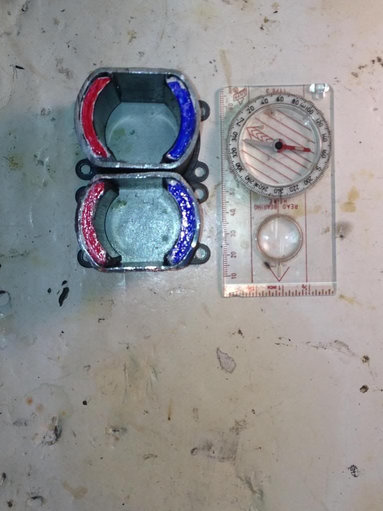
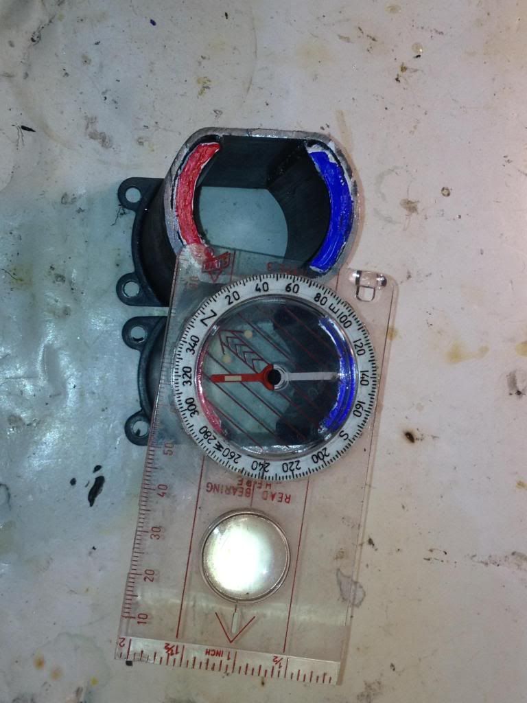
    Sorry got an arc welder only, did OK, a little sloppy. Here is a diagram showing what you say about how to join the bodies and line up magnet Polarities. Join Red to Red, blue to blue. For compass needle, red is North.


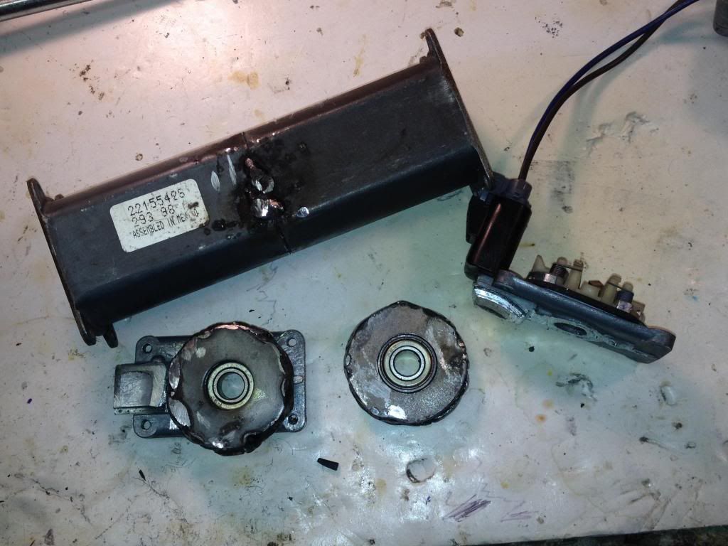
    Here is the the body spot welded on either side, away from magnets, wet down paper inside to keep them cool.


    Used washers for bearing housings, welded them together. May have trouble getting behind the brushes to bolt the housings down. Good idea about the aluminum, next time...

    You could leave a gap between both rotors, so they align exactly with both pair of magnets (I am assuming you will have a gap also between both magnets pairs right?)...it will not hurt the performance...is like two motors assembled by one shaft...then wind it running wires straight down...ignoring 1/4 inch rotor gap...understand?
    I made the cut at the magnets, so they were flush with the body, and when put together there was no gap. I'm sure that would provide max field strength that way. I got the extra parts so I will make the double rotor as bigger.

    Leave a comment:


  • Ufopolitics
    replied
    [QUOTE=shylo;253821]

    Now the Geometrical Shape does not need to be a cylinder...but any shape...like we have here a "Y" Core...if you add the Neo at bottom of "Y" you will get the Southern Pole split at two upper ends from "Y"..
    Hi UFO, Yes I agree, but , We have an opposite magnet attached to the ends of that ..Y.. One is a N stator, and the other a S stator ....The south will repel, The north will attract,.....will it not all go to the north side??
    That is exactly what we want!...the Rotor redirected South from N1 to be repelling from S Stator, and be attracted to North Stator...and so happens on the Top...where N1 is repelled by Left N Stator and Attracted by Right South Stator...and before Coils reach the "locking point" N1 would be disconnected from Input and N2 will be On...and so on...and on and on...like the Duracell Rabbit...the Cycle repeats...

    One thing you must realize is that the Diverged/redirected South at the two bottom poles of the "Y" have a "Spatial Bisector" (not on Steel Core) EXACTLY at Center between both Poles...Meaning that its "Locking Point" or when Stator North Center meets that center Spatial imaginary line...and NOT at the center from S Pole at N2 nor N3...and I believe here is where you are confused.

    Rewinding on the 16 pole again, where the coils cross seems to be the key.
    With four stators I'm splitting A group to face each North stator.
    Five groups so far .....way fast.
    artv
    Great!, yes indeed this All North Group winding would be the Top Notch...also generating output, plus reducing even more amp draw...

    So, you can fit more wires/turns than before with Pairs?

    Please Arty, let Us know your results...


    Thanks


    Ufopolitics
    Last edited by Ufopolitics; 04-10-2014, 10:25 PM.

    Leave a comment:


  • shylo
    replied
    Exactly

    [QUOTE]

    Now the Geometrical Shape does not need to be a cylinder...but any shape...like we have here a "Y" Core...if you add the Neo at bottom of "Y" you will get the Southern Pole split at two upper ends from "Y"..

    Hi UFO, Yes I agree, but , We have an opposite magnet attached to the ends of that ..Y.. One is a N stator, and the other a S stator ....The south will repel, The north will attract,.....will it not all go to the north side??

    Rewinding on the 16 pole again, where the coils cross seems to be the key.
    With four stators I'm splitting A group to face each North stator.
    Five groups so far .....way fast.
    artv

    Leave a comment:


  • Ufopolitics
    replied
    Ten Poles All North Pairs and Groups Variations

    Hello to All,

    The Ten poles as seen on last video was wound as a P-10 (Ten Pairs):

    [IMG][/IMG]

    I made it out of my Sullivan Starter Motor for Gas R/C Helicopters, converted to Asymmetrical previously...Now I am going to re-wind it according to 10 Groups, NOT Pairs...so is a "G-10":

    [IMG][/IMG]

    Don't get scared, it may look complicated but it is NOT...is just to "see" what we are doing here...

    In Pairs Winding, each Coil wrapped around Three Poles, so Six (6) for Pair...and now in Groups we are comprehending same Total of Six (6) Poles for each Group.

    Every Group have Four (4) Coils, instead Pairs having Two (2) Coils...so, we fit Four Coils into Six Poles by Overlapping every pole.

    We are using exactly SAME Commutator Element as on Pairs.

    We would be able to fit more copper, more turns, as also leave less air gaps, plus other attributes related to performance...

    The way I recommend to wind this is to start like P1 in Blue...then winding next P10, then P9 and so on...so the displacement of wires sets better into each other overlapped Coils Group slots.

    Regards


    Ufopolitics

    Leave a comment:


  • Ufopolitics
    replied
    Magnetic Redirection Example

    Hello to All,

    Note: I know many of you guys know this already...nothing new...but some other people don't...or maybe you have not observed this specific design in detail before...
    This is related to the way Magnetic Poles could be Redirected or Diverged through steel cores...This fact could let us identify where our poles are going to...as well as helping in future designs...

    [IMG][/IMG]

    Any Car/Vehicle Alternator Rotor is designed like this...

    Look at main coil feeding through upper slip rings...it "normally" projects its polarity as reflected by N1-S1...as the Main Poles...However, thanks to the "Jaw Design" upper and lower... made out of solid steel...the North and South poles are being redirected to split into every teeth creating an additional flow of B Fields or lines of force between them.

    Resuming through this design...a Coil which is Axially Magnetically Polarized...is now doing it Radially, thanks to the Jaw-Teeth splitting design.

    This is done in order to directly interact with the generating windings which are disposed Radially on the outer housing.

    The point is...that we could create MANY Designs where we would be able to "Diverge" or "Redirect" our Coils Magnetic Poles through Steel Components...it is a very useful knowledge to expand our designs as well as to understand what I was explaining related to the Three Poles Asymmetric Motor...redirecting its N1 South to bottom Poles of N2-N3...


    Regards


    Ufopolitics
    Last edited by Ufopolitics; 04-10-2014, 02:15 PM.

    Leave a comment:


  • Ufopolitics
    replied
    Poles redirection

    Originally posted by shylo View Post
    So, let's make it simple...

    N1 Coil when activated develop a force F1, based on a dual action, repulse-attract...which is simultaneously "reinforced" by a redirection of its South Polarity to S-1A and S-1B outer circumference of "South Hemisphere" of rotor core, producing a force F2.

    Hi UFO, Now I'm getting confused , the south pole created by N1 , you are saying goes towards both dead poles ? Would it not just go directly to the north pole rotor core , since the south pole rotor core would repel it.
    Hello Shylo,

    Nope, the redirection of a Magnetic Pole, in this case generated by N1, South pole travels all the way through the steel laminations , passing the shaft...going to both lower poles N2-N3, ending right at those outer poles faces...then N1 North lines of force will go all the way down to start "entering" through them, now south.

    The experiment to prove this is very simple...Get a NON MAGNETIZED solid steel cylinder rod then add a strong Neo cylinder Magnet and stick its SOUTH Pole to one end of steel cylinder...get a compass...then try to find where the South from the Neo is now...you will see it is all the way to the other end of your steel cylinder...and no longer at Neo's end...understand?
    You could verify this also by getting another magnet near by that steel cylinder end.

    Now the Geometrical Shape does not need to be a cylinder...but any shape...like we have here a "Y" Core...if you add the Neo at bottom of "Y" you will get the Southern Pole split at two upper ends from "Y"...

    I've think the higher we go in poles the more complex it is going to get.
    I have 2 five pole motors , I will wind it just as you show, I'm just not sure what wire to use . All my stuff is salvaged.
    Thanks artv
    The wire size is related to the rotor mass as also to the magnets strength...if they are bigger than the Radio Shack motor...then use a 26 awg...not a 30.


    Regards


    Ufopolitics
    Last edited by Ufopolitics; 04-10-2014, 01:54 PM.

    Leave a comment:


  • Ufopolitics
    replied
    Nice project Sam!

    Originally posted by sampojo View Post
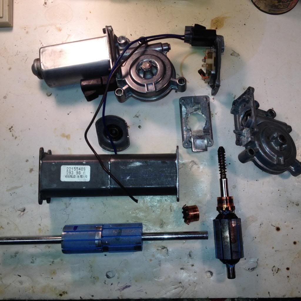
    Exploded view, top left shows fully assembled original part


    Converting to a double rotor takes the guess work out of adding the second brush plate. Just cut off back end of motor and join two bodies. I will arc weld them together, being very careful about keeping the magnets cool as possible.
    Hey Sam,

    Make sure the cut to be welded surfaces are TRUE 90º otherwise rotor will bind on magnets, and just tack it with MIG Welder on the corners and then run a test with rotor on...easier to cut and re-align...

    Use a soaked cold water rag inside where magnets go.

    But MAINLY make sure Stator Magnets are ALIGNED South top South Bottom...and North/North...use a small plastic compass inside and mark them...before welding housings !!


    3/8" stock shaft takes the two armatures. I remove the bushings and use bearings which will be mounted in large steel washers bolted to the front of the wired brush plates. One is shown.
    Great idea to use bearings...could you make like pretty thick gauge Aluminum rectangular Plates with hole centered to press bearings and bolt to brush caps/housing?...it would be a piece of cake to R&I plus align that way...


    It will use the diagram just posted by UFO as it is a ten pole also.
    Hold on there friend!...I will post a Ten Pole 10 GROUP Diagram later on...which is the one am doing next (in case you wanna do that one instead)...to see advantages versus the one I tested on video...I am taking that one apart and re-winding it, probably start today...since I do not have another identical to compare.
    But first am making a video reading parameters and running at same voltages before taking it apart.

    The good thing about this pattern is that it seems to use the same brush to stator orientation as the symmetric motor chosen for the conversion. The double rotor will make the motor much more powerful. I will need to add another half inch of rotor, since these sat 1/4" back from the end of the motor.
    You could leave a gap between both rotors, so they align exactly with both pair of magnets (I am assuming you will have a gap also between both magnets pairs right?)...it will not hurt the performance...is like two motors assembled by one shaft...then wind it running wires straight down...ignoring 1/4 inch rotor gap...understand?

    I already have built a 10-pole quad stator with the quad pentagon-Y winding pattern. It ran at 9000 rpm on 12v. They will be fun to compare.
    Definitively it would be fun...


    Regards


    Ufopolitics
    Last edited by Ufopolitics; 04-10-2014, 11:00 AM.

    Leave a comment:

Working...
X