Announcement

Collapse
No announcement yet.

My Asymmetric Electrodynamic Machines

Collapse
X
 
  • Filter
  • Time
  • Show
Clear All
new posts

  • sampojo
    replied
    GM window regulator conversion

    Exploded view, top left shows fully assembled original part


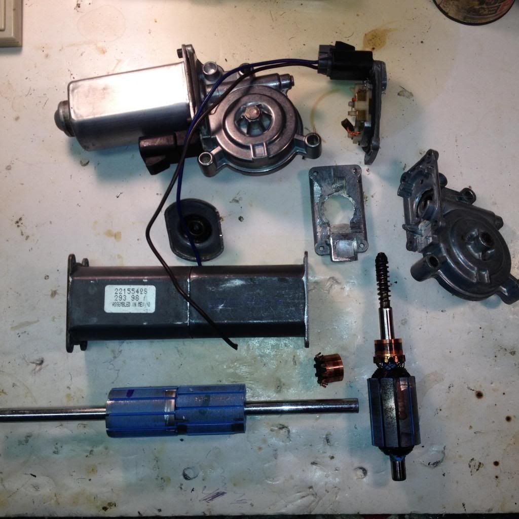
    Converting to a double rotor takes the guess work out of adding the second brush plate. Just cut off back end of motor and join two bodies. I will arc weld them together, being very careful about keeping the magnets cool as possible.

    3/8" stock shaft takes the two armatures. I remove the bushings and use bearings which will be mounted in large steel washers bolted to the front of the wired brush plates. One is shown. It will use the diagram just posted by UFO as it is a ten pole also. The good thing about this pattern is that it seems to use the same brush to stator orientation as the symmetric motor chosen for the conversion. The double rotor will make the motor much more powerful. I will need to add another half inch of rotor, since these sat 1/4" back from the end of the motor. I already have built a 10-pole quad stator with the quad pentagon-Y winding pattern. It ran at 9000 rpm on 12v. They will be fun to compare.
    Last edited by sampojo; 04-10-2014, 04:58 AM.

    Leave a comment:


  • Ufopolitics
    replied
    Regenerative Acceleration Under Load...

    Hello My Friends,

    Well, here is the Video about the P-10 All North Tests...

    https://www.youtube.com/watch?v=-DUK...ature=youtu.be

    [IMG][/IMG]

    And like I said on Video...This Motor Configuration (with this small Power Source) will not show a huge Increase on RPM's acceleration like the small RS Five Pole did, #1 because of mass, and second Coils size and Capacitance...HOWEVER...IT DOES INCREASE UNDER LOAD!...Never decreasing, but JUST for a few seconds till it stabilizes back then start the "ASCENSION TO HEAVENS" Curve...

    Now, the second Test I did on Video is just to clear doubts...mainly at my You Tube Channel...some comments I will quote below...which I find "Logical and Making Sense" though...Big Claims require Big Time Proof...Big Time Testing...and I agree 100%...plus many have the right to doubt them.

    Good test. The first part of the video. The motor is not loaded down by the bulb, because it runs faster by 1200RPM under load. The power supply is out putting an extra 0.7A for the bulb. It is a good and efficient motor design. It uses low current per RPM. Good development and progress.
    Sorry Guy...PSU either did not wanted-this time only- to put that xtra power now??!!

    Anyways, this is fun...

    The Second Test...I clearly show that Power Source can NOT put out with both components at once, Bulb and Motor...no matter how...I connected them...tried in Parallel...Motor Collapses...PSU Relay of overload clicks in...PLUS in series does only 2600 RPM's plus a dimmer Bulb..

    Now...what happened?...where is that Energy coming from?...that ONLY with Motor feeding Bulb through its Generation Gates...it can do OVER 5000 RPM's PLUS keeping Bulb brightly ON??!!

    And we are not lighting here CFL's...NOR LED'S...


    Enjoy it Guys


    Au Revoir


    Ufopolitics

    Leave a comment:


  • shylo
    replied
    pole direction

    So, let's make it simple...

    N1 Coil when activated develop a force F1, based on a dual action, repulse-attract...which is simultaneously "reinforced" by a redirection of its South Polarity to S-1A and S-1B outer circumference of "South Hemisphere" of rotor core, producing a force F2.

    Hi UFO, Now I'm getting confused , the south pole created by N1 , you are saying goes towards both dead poles ? Would it not just go directly to the north pole rotor core , since the south pole rotor core would repel it.

    I've think the higher we go in poles the more complex it is going to get.
    I have 2 five pole motors , I will wind it just as you show, I'm just not sure what wire to use . All my stuff is salvaged.
    Thanks artv

    Leave a comment:


  • sampojo
    replied
    Originally posted by Ufopolitics View Post
    Hello Sam,

    Sam, Sam...Magnetic Fields are Dynamic Spatial Forces that move through waves that undulate...curves that softly, smoothly, yet very strong project into three dimensional space...

    Please read Bearden...about Heaviside and Poincaré Giant Electromagnetic Curl Calculations...read Maxwell...read Faraday...please.

    They calculated and developed ways to measure magnetic fields...some using High Level Algebra Equations...like Maxwell used Quaternion Formulas...as also Integers approximating the areas of "Non Regular/Typical" GEOMETRIC VOLUMES like a Magnetic Field IS...Every single Geometrical Volume has a Mathematical Formula based on revolving, extruding...moving a 2D Component or Curve into space...

    Only then you will realize that Hendrick Lorentz RIGID, STRAIGHT and STATIC VECTORS using only One and Two Dimensions are NOT THE WAY...to even "Imagine"...much less Capable to Calculate not even "near" the 3D Dynamics of Magnetism geometries...limiting its MAJESTIC POWER within mere and simple straight lines with a "pointy" arrow...


    So...You are saying above...You are completely doubting about what I have stated...?!

    Have You ever build a Three Pole Asymmetrical Machine?

    Have You build the Five Pole RS ALL North yet?...then compare it to your Three Pole?

    Because I HAVE...and NOT ONLY ONE MODEL OF EACH...Sam!


    Ideas are not "good or bad" Sam...until proven they do what we claim...only then, they become Great Ideas...otherwise is pure speculation...

    If You know how the Main Rotor Coil of a Car Alternator propagates its Magnetic Field into Space...and how the upper and lower "Jaws" made out of solid Steel ...take those North and South poles and DIVERT/REDIRECT them in EXACTLY a 90º Angle to aim at Generating Fields...PLUS, Alternating into MANY South-Norths "Teeth"...then this "weakening" Vector Theory...will not apply?

    Your Vector approach to the 3 pole is wrong Friend...by having a WIDER Angle between both Southern Poles of N2-N3...This creates an AMPLIFICATION of the Magnetic Field Spatial Spectrum...widening its Bisector (Which is the Strongest Area of Field)...MUCH BIGGER than the Compact North Pole N1...which is strong, but like a very fine needle.

    Also, You are completely ignoring the Generating/Induction and Transformer Properties processes, PLUS, the Collapsing Coil "Attributes" that N2-N3 are going through when passing in front of the lower Stator Field...and they are very important not to forget about them Sam...

    Related to your Design at bottom of Post...I see it Too Rigid...too square, not showing a Progression...a movement...remember Motors, Generators are rotating machines...they must comply with the wind...with the "Spiral Forces" of rotating masses you see in Nature everyday...

    Look at the sky Sam...look at the swirls that higher altitude clouds like stratocumulus, cumulus nimbos...cirrus...etc,etc...they are "painting" the higher winds for Us to see...now...do you see many straight lines, and squares there Sam?...

    But then again...your design above is just an idea...so MAKE IT HAPPEN!!...THEN...prove me wrong...


    Cheers


    Ufopolitics
    Hi Ufo, I like your viewpoint. Reminds me of what Schauberger had said, about his repulsine development, the need to observe nature in its flows and swirls. Just a mental flight back to the darkness on my part? I don't have time for wandering around in the woods right now and am sorely eager to just to claim the performance of your existing unipolar findings. As soon as I get some really good stuff built, there is a very interesting physics professor in the local university I hope to impress. Maybe he can teach me Heaviside and asymmetric Maxwell equations (once I show them to him maybe). Yeah I kinda need a classroom situation to pound equations into my head.

    While my mind had a minor diversion, my hands have been busy (in between sessions with our US Marxist progressive income tax, duly bureaucratic, overly complex, distributionist, property and freedom robbing). Unless you think you may supercede it soon, I am marching toward your recently posted 10p-2s unipolar design. I am building a double rotor GM window motor (regulator as they say). Here are the basic parameters.

    1. Raise original 24 ga used to 26ga
    2. Double rotor means just cutting the back of the motor off and welding bodies together. As Valerie Jarod says, easy peasy.
    3. Attempt about a 1 ohm winding per group. looking like 28' per group. running some calculations...

    I will post pics soon.

    If your synapsis are about to supercede all previous work, and I should hold up, just shout it out. Greatly appreciated.
    Last edited by sampojo; 04-09-2014, 03:55 PM.

    Leave a comment:


  • Ufopolitics
    replied
    Thank You

    Originally posted by BroMikey View Post
    @UFO

    I just love your video to death. You Sir are a great man for that thank you.

    I am impressed when men speak up and remember God and HIS power, the rest can show us something but their is something more here. God does not take it lightly and is a friend to those who are not ashamed of HIM.

    The motor designs are generally doing the recycling like other designs.

    Great work and yes I understood much of what you talked about. Ac motors DC motors Pulse DC motors yes and yes.

    I have 2 twenty HP motors here that are 3 phase and 2 one hundred HP 3ph units as well. Some PM motors too.

    I love building John Bedini solid state Oscillators.

    Thanks Again UFO I see you are in deed a man to take note of.

    God Bless.

    Michael
    Hello Michael and Thank You!

    Thanks for such kind words, believe it or not...you have no idea...how they are like "Energy" for me to keep going on... here...

    I am very glad you understood my explanation and videos...


    Regards


    Ufopolitics

    Leave a comment:


  • Ufopolitics
    replied
    Originally posted by sampojo View Post
    I have been thinking alot about this and want to offer another analysis using vectors to represent the magnetic fields.
    Hello Sam,

    Sam, Sam...Magnetic Fields are Dynamic Spatial Forces that move through waves that undulate...curves that softly, smoothly, yet very strong project into three dimensional space...

    Please read Bearden...about Heaviside and Poincaré Giant Electromagnetic Curl Calculations...read Maxwell...read Faraday...please.

    They calculated and developed ways to measure magnetic fields...some using High Level Algebra Equations...like Maxwell used Quaternion Formulas...as also Integers approximating the areas of "Non Regular/Typical" GEOMETRIC VOLUMES like a Magnetic Field IS...Every single Geometrical Volume has a Mathematical Formula based on revolving, extruding...moving a 2D Component or Curve into space...

    Only then you will realize that Hendrick Lorentz RIGID, STRAIGHT and STATIC VECTORS using only One and Two Dimensions are NOT THE WAY...to even "Imagine"...much less Capable to Calculate not even "near" the 3D Dynamics of Magnetism geometries...limiting its MAJESTIC POWER within mere and simple straight lines with a "pointy" arrow...


    Originally Posted by Ufopolitics Post 6460
    Hello to All,

    In a "brief" Conclusion on this First Part: Even though, the FIVE POLE...with the Two redirected South Poles above... are Assisting Rotation...which enhances the Performance over the previous N-S Asymmetric Model...STILL, is reduced in "QUALITY and Quantity" over the THREE POLES Structure...which is obviously amplified at larger angles in comparison to the NARROWER Angle depicted by ONLY TWO POLES of the Five Poles Rotor, Between BOTH MACHINES IDENTICAL STATORS positioning...

    Ufopolitics

    I think the two poles South poles of the 5 pole RS style motor is stronger than the three pole motor south poles, contrary to the above paragraph if I understand it correctly.

    So...You are saying above...You are completely doubting about what I have stated...?!

    Have You ever build a Three Pole Asymmetrical Machine?

    Have You build the Five Pole RS ALL North yet?...then compare it to your Three Pole?

    Because I HAVE...and NOT ONLY ONE MODEL OF EACH...Sam!


    Here are diagrams of both style rotors with some vector analysis, the 3-pole first:


    Notice how the vertical brown vector is shorter, and the stronger gray vectors are stronger but cancel each other out. Their strength is lost for use in rotation.

    Below the RS 5-pole with vectors added:


    Notice how the brown vectors, the North vertical Y-component is longer and stronger, and the cancelling gray X-component vectors are shorter. Overall the N Y-component should sum up larger and stronger.

    In general the south pole component contribution to rotation is weaker since it further away from the stators, strength decreasing inversely proportional to the distance, for the most part

    If the three pole performance is better, I propose that the North pole be examined. Notice how concentrated the North pole of a 3-pole coil will be, since the coil is very narrow. The narrower the coil, the stronger the magnetic force will be at the exit point meeting the stators. Now lets look at a North pole unipolar winding using a 20-pole rotor.


    Lots of coils coming in at angles, with the X-components all fight each other, losing strength.

    So the question may be, "How could a motor be wound to minimize cancelling X-vectors?" I propose the following:


    Although the larger half of a given coil will have a weaker field the inner one will serve to concentrate it. I a bigger motor these coil groups would be done in 2 layers and staggered, maintaining the orientation with its comm segment. Since the inner coils would be farther away, it could have more turns, but that could mean different gauges.

    And this thought finally wormed its way into my cerebrum. Why not wind the motor just like the three pole, one pole at a time? This might get the most copper on the rotor too, as the above method would leave air gaps in the larger coils.

    bad ideas Ufo?
    Ideas are not "good or bad" Sam...until proven they do what we claim...only then, they become Great Ideas...otherwise is pure speculation...

    If You know how the Main Rotor Coil of a Car Alternator propagates its Magnetic Field into Space...and how the upper and lower "Jaws" made out of solid Steel ...take those North and South poles and DIVERT/REDIRECT them in EXACTLY a 90º Angle to aim at Generating Fields...PLUS, Alternating into MANY South-Norths "Teeth"...then this "weakening" Vector Theory...will not apply?

    Your Vector approach to the 3 pole is wrong Friend...by having a WIDER Angle between both Southern Poles of N2-N3...This creates an AMPLIFICATION of the Magnetic Field Spatial Spectrum...widening its Bisector (Which is the Strongest Area of Field)...MUCH BIGGER than the Compact North Pole N1...which is strong, but like a very fine needle.

    Also, You are completely ignoring the Generating/Induction and Transformer Properties processes, PLUS, the Collapsing Coil "Attributes" that N2-N3 are going through when passing in front of the lower Stator Field...and they are very important not to forget about them Sam...

    Related to your Design at bottom of Post...I see it Too Rigid...too square, not showing a Progression...a movement...remember Motors, Generators are rotating machines...they must comply with the wind...with the "Spiral Forces" of rotating masses you see in Nature everyday...

    Look at the sky Sam...look at the swirls that higher altitude clouds like stratocumulus, cumulus nimbos...cirrus...etc,etc...they are "painting" the higher winds for Us to see...now...do you see many straight lines, and squares there Sam?...

    But then again...your design above is just an idea...so MAKE IT HAPPEN!!...THEN...prove me wrong...


    Cheers


    Ufopolitics
    Last edited by Ufopolitics; 04-09-2014, 01:55 PM.

    Leave a comment:


  • BroMikey
    replied
    Understanding this Motor

    Originally posted by Ufopolitics View Post
    Hello BroMikey and welcome,

    This is about a New Methodology and not just a different way to wind an existing motor "as is"...I will try to explain as a "Generalization". However, "a simple answer" would be kind of hard to "briefly" explain this whole technology, plus DC Motor fundamental knowledge is required for easier understanding.


    We build Motors here, where "unused" Energy flows out, back to our sources to be utilized or stored back.

    We enhance Motor Performance with this new tech, where Torque and Speed Parameters no longer co-exist as Inversely Proportional (meaning we can only have one Parameter at top performance, sacrificing the second one to lower spec's)...but directly proportional, where Speed and Torque are achieved equally in an ascending curve.

    This type of Motors would "take" higher potentials ranges (Voltages) as higher densities of Currents (Amperage) where Closed Systems could never afford to "process", since they are limited by closed looping of its rotor coils.

    STRUCTURAL MODIFYING

    Motors structure must be modified, as adding a second commutator on the other side of rotor shaft, in some cases shaft must be replaced by a longer one, as outer casing/housing also must be "elongated" to fit the dual commutators rotor assembly.

    COILS WINDING

    Once structure is modified, then winding process is also different from existing motors.

    On any existing Motor the winding is a continuous series looping that closes at the end of last wound coil, meaning, all wires are short circuited...or called "Closed Winding".

    In my Methodology Coils are Isolated or "Open" related to next ones in the Sequence. In order that each coil gets Energized separately when making contact, then by an action of either repulse or attract, or both, it automatically/mechanically, disconnects from contact, pushing or pulling next Coil in line. Disconnected Coils travel to a second Gate-Brush, where it "exhaust" its charge as an output.

    This way All Coils get a "brake" or an "idling" stage at disconnection, cooling off, plus getting induced by traveling in front of Stators Magnetic Fields, then reaching Output Stage.

    Did You see my video ASYMMETRY TO ENLIGHTENMENT ?

    Did You read my ABSTRACT at Introduction First Page of this Thread?:


    Hope this post will help you to understand it better...


    Regards


    Ufopolitics
    @UFO

    I just love your video to death. You Sir are a great man for that thank you.

    I am impressed when men speak up and remember God and HIS power, the rest can show us something but their is something more here. God does not take it lightly and is a friend to those who are not ashamed of HIM.

    The motor designs are generally doing the recycling like other designs.

    Great work and yes I understood much of what you talked about. Ac motors DC motors Pulse DC motors yes and yes.

    I have 2 twenty HP motors here that are 3 phase and 2 one hundred HP 3ph units as well. Some PM motors too.

    I love building John Bedini solid state Oscillators.

    Thanks Again UFO I see you are in deed a man to take note of.

    God Bless.

    Michael

    Leave a comment:


  • sampojo
    replied
    RE: Magnificence of Three post 6460

    Originally posted by Ufopolitics Post 6460
    Hello to All,

    In a "brief" Conclusion on this First Part: Even though, the FIVE POLE...with the Two redirected South Poles above... are Assisting Rotation...which enhances the Performance over the previous N-S Asymmetric Model...STILL, is reduced in "QUALITY and Quantity" over the THREE POLES Structure...which is obviously amplified at larger angles in comparison to the NARROWER Angle depicted by ONLY TWO POLES of the Five Poles Rotor, Between BOTH MACHINES IDENTICAL STATORS positioning...

    Ufopolitics
    I have been thinking alot about this and want to offer another analysis using vectors to represent the magnetic fields. I think the two poles South poles of the 5 pole RS style motor is stronger than the three pole motor south poles, contrary to the above paragraph if I understand it correctly. Here are diagrams of both style rotors with some vector analysis, the 3-pole first:


    Notice how the vertical brown vector is shorter, and the stronger gray vectors are stronger but cancel each other out. Their strength is lost for use in rotation.

    Below the RS 5-pole with vectors added:


    Notice how the brown vectors, the North vertical Y-component is longer and stronger, and the cancelling gray X-component vectors are shorter. Overall the N Y-component should sum up larger and stronger.

    In general the south pole component contribution to rotation is weaker since it further away from the stators, strength decreasing inversely proportional to the distance, for the most part

    If the three pole performance is better, I propose that the North pole be examined. Notice how concentrated the North pole of a 3-pole coil will be, since the coil is very narrow. The narrower the coil, the stronger the magnetic force will be at the exit point meeting the stators. Now lets look at a North pole unipolar winding using a 20-pole rotor.


    Lots of coils coming in at angles, with the X-components all fight each other, losing strength.

    So the question may be, "How could a motor be wound to minimize cancelling X-vectors?" I propose the following:


    Although the larger half of a given coil will have a weaker field the inner one will serve to concentrate it. I a bigger motor these coil groups would be done in 2 layers and staggered, maintaining the orientation with its comm segment. Since the inner coils would be farther away, it could have more turns, but that could mean different gauges.

    And this thought finally wormed its way into my cerebrum. Why not wind the motor just like the three pole, one pole at a time? This might get the most copper on the rotor too, as the above method would leave air gaps in the larger coils.

    bad ideas Ufo?
    Last edited by sampojo; 04-09-2014, 04:56 AM.

    Leave a comment:


  • Ufopolitics
    replied
    A Generalization...

    Originally posted by BroMikey View Post
    Hello UFO

    What does it do when the wind is done this way? Just a generalization.

    I am sort of green and I see all of these motors and I can't understand what they are doing different after it is done this way.

    Thanks for a simple answer in advance.

    Mike ps it's like nothing else I know of so I better ask
    Hello BroMikey and welcome,

    This is about a New Methodology and not just a different way to wind an existing motor "as is"...I will try to explain as a "Generalization". However, "a simple answer" would be kind of hard to "briefly" explain this whole technology, plus DC Motor fundamental knowledge is required for easier understanding.

    What does it do?
    We build Motors here, where "unused" Energy flows out, back to our sources to be utilized or stored back.

    We enhance Motor Performance with this new tech, where Torque and Speed Parameters no longer co-exist as Inversely Proportional (meaning we can only have one Parameter at top performance, sacrificing the second one to lower spec's)...but directly proportional, where Speed and Torque are achieved equally in an ascending curve.

    This type of Motors would "take" higher potentials ranges (Voltages) as higher densities of Currents (Amperage) where Closed Systems could never afford to "process", since they are limited by closed looping of its rotor coils.

    STRUCTURAL MODIFYING

    Motors structure must be modified, as adding a second commutator on the other side of rotor shaft, in some cases shaft must be replaced by a longer one, as outer casing/housing also must be "elongated" to fit the dual commutators rotor assembly.

    COILS WINDING

    Once structure is modified, then winding process is also different from existing motors.

    On any existing Motor the winding is a continuous series looping that closes at the end of last wound coil, meaning, all wires are short circuited...or called "Closed Winding".

    In my Methodology Coils are Isolated or "Open" related to next ones in the Sequence. In order that each coil gets Energized separately when making contact, then by an action of either repulse or attract, or both, it automatically/mechanically, disconnects from contact, pushing or pulling next Coil in line. Disconnected Coils travel to a second Gate-Brush, where it "exhaust" its charge as an output.

    This way All Coils get a "brake" or an "idling" stage at disconnection, cooling off, plus getting induced by traveling in front of Stators Magnetic Fields, then reaching Output Stage.

    Did You see my video ASYMMETRY TO ENLIGHTENMENT ?

    Did You read my ABSTRACT at Introduction First Page of this Thread?:

    ABSTRACT

    A new concept to the Art of Electromagnetic Rotation Methodology, that includes new structuring of the Mechanical Architecture of an Electric Motor and/or Generator or combination thereof, extending to the methods for processing their Input-Output governing data.

    Static and rotational components, particularly individual isolated groups of coil elements performing dual functions as a Motor and as a Generator at specific angles within the 360 degrees of rotation. An specific and unique feature of this methodology is the non reversal of the input current-voltage polarity within the actuating individual isolated coils during the motor stages, causing a non changing magnetic field pole projection due to a one sense or direction magnetic flux in their respective cores, rotation occurs by switching intervals of On and Off Times at specific positioning, such that a repulsion and/or attraction is constantly obtained at T-On, of individually orderly sequenced North-South poles.

    This particular switching times On and Off creates a one direction, non colliding electronic flow within the isolated conductive coil elements deriving into a pulsating current dropping to zero (at T Off) to Max V in (at T On), equivalent switching codes as to the electronically controlled Pulse Width Modulation (PWM) utilized to control the current feeding input in Electric Motors and the Input-Output parameters of Power Source Converters, this identical Data-Transfer, based on Pulsed Signals, establishes a common language of operation between machine and input-output control commands, leading into a robust communication protocol.

    The advantages that comprises a Motor and/or a Generator driven directly from the core by pulsed signals, extend to the incorporation of Optoelectronic s as to replace the Old Fashion, brush-commutator switching systems by an emitting pulsed width modulated (Infrared PWM as an example) or linear optical signal (Signaling steadily where On Off occurs by mechanical-magnetic loosing angle of interaction) to an Optoelectronic receiver connected to the Power Switching Executing circuits, delivering a less friction, low noise, more accurate and precise communication Network.
    Hope this post will help you to understand it better...


    Regards


    Ufopolitics

    Leave a comment:


  • iankoglin
    replied
    Originally posted by marxist View Post
    Hi Kogs,
    thanks for the info, I didn't know that ufo's drawings actually contained all these details. Thanks.

    Want to take the opportunity to ask: In order to fit experimental motors with a second commutator - which seems to be essential, if one wants to follow ufo's design - one needs to disassemble a second motor, take its commutator and fit that to the experimental motor.

    How does one get a commutator off the shaft to re-use it on another motor?
    Do you just twist it off with a pair of pliers?
    G'day Marxist
    If you read from the start of this thread a lot of questions you are asking have been asked and answered already I suggest that you read and look for these answers as it takes time for others to look up these answers by doing so you will find answerers before you ask them
    Kindest Regards

    Kogs trying to help

    Leave a comment:


  • marxist
    replied
    2 are a pair. no third present

    Hi Garry,
    just saw that you answered my question about salvaging commutators. Thanks.

    Regarding the "third coil of the pair":
    I have attached a screen-shot from ufo's video "ALL_NN_FIVE_POLES " https://www.youtube.com/watch?v=RSs2beNfAP8, which shows coil-pair 1.

    I see 2 coils which make one NN-pair. No third coil present, in my understanding.
    Let's see what Kogs says.

    edit: ok, when trying to see your problem, I guess one could say:
    the coils of the pair "share" one rotor pole (see attached screen shot) and one could probably say, that the wire strands on either side of that shared pole AUTOMATICALLY form a kind of a third coil ...
    Attached Files
    Last edited by marxist; 04-08-2014, 07:33 AM.

    Leave a comment:


  • GChilders
    replied
    Taking off the commutator

    @Marxist

    I cannot recommend trying to twist off the commutators on a goldmine with a pair of pliers. The center of the commutator on these motors is plastic and very fragile. What I have done and many others also is to drill a 4mm hole in a two by four block of lumber and either put one end of the rotor shaft, after the magnet wire has been stripped, into a vise and press the shaft down. Then take a piece of welding rod and drive the shaft the rest of the way out. Some have left the shaft in and driven another shaft in from that side. I find that the rotors will eventually break if you use this method. I have ordered 4mm drill rod and made new shafts for all of my replications. This has been a very satisfactory solution. After driving the old shaft carefully all the way out you will have a commutator 2 spacer bushings and the rotor body. After I disassemble two motors, I take the new shaft and assemble the new rotor with two of the bushings from one motor and the commutators from both motors. I use epoxy to hold the assembly together. If you don't have a large enough vise to press the pieces of the rotor apart. What I have done in the past is drive them apart with a hammer. This may bend the shaft if not done carefully. I use the same two by four block of lumber and drill a 4 mm hole in it. Put the shaft with the commutator against the block and drive the shaft down to the spacer bushing. Once again pulling out a piece of welding rod or an old shaft that has been ground smooth drive the rod the rest of the way out. I have lost occasionally a rotor and also commutators with this method. handle the hammer with care.

    Cheers

    Garry

    Leave a comment:


  • GChilders
    replied
    third coil

    @Kogs and Marxist

    I am not confused about the coil pairs or the commutator connections. It seems that there is a third coil being created between the two pairs. Maybe I am just confused by the use of the term interleave which seems to me to mean that as the pair of coils is being wound a third coil is created between the two main coils. I am trying to clarify if I am understanding that correctly. It seems in the video although it is hard to see that around what is marked as p1 between the two slots a third coil is being wound. Call me crazy but I think that is a significant difference between this wind and all of the other winds. Am I completely off base or do you see that third coil being wound also?

    Cheers

    Garry

    Leave a comment:


  • marxist
    replied
    Originally posted by iankoglin View Post
    .... there is 2 connections one each to 2 commutators
    They are depicted in the drawings the inner is the Bottom comm element and the outer is the Top comm element
    Hi Kogs,
    thanks for the info, I didn't know that ufo's drawings actually contained all these details. Thanks.

    Want to take the opportunity to ask: In order to fit experimental motors with a second commutator - which seems to be essential, if one wants to follow ufo's design - one needs to disassemble a second motor, take its commutator and fit that to the experimental motor.

    How does one get a commutator off the shaft to re-use it on another motor?
    Do you just twist it off with a pair of pliers?
    Last edited by marxist; 04-08-2014, 06:00 AM.

    Leave a comment:


  • iankoglin
    replied
    Originally posted by marxist View Post
    Hi Garry,

    I see Kogs tried to clarify already.
    However there is just one basic misunderstanding, as far as I can see:
    "P-1" on the rotor body does NOT mean "rotor pole 1"
    It means "coil pair 1", with the double-sided arrow pointing to the dark blue "wires" of that coil pair.
    and
    "P-1" on the commutator means "commutator element connected to coil pair 1"
    G'day marxis
    You are right but to clarify there is 2 connections one each to 2 commutators
    They are depicted in the drawings the inner is the Bottom comm element and the outer is the Top comm element

    Kindest Regards

    Kogs just clarifying

    Leave a comment:

Working...
X