Announcement

Collapse
No announcement yet.

My Asymmetric Electrodynamic Machines

Collapse
X
 
  • Filter
  • Time
  • Show
Clear All
new posts

  • Great and Welcome Zardox!

    Originally posted by Zardox View Post
    Just finished winding the radio shack motor with the dual pentagon and did a preliminary run and it seems to run great. I put some nail polish enamel on the windings and am waiting for that to dry before I weld the case back together and do more testing.
    I also wanted to say that I used the original wire that I originally removed from the armature. I measured each one (they were all a little different) and cut them off at 9'. I then marked the 4-1/2' with tape before winding the first South coils.
    Let you know when I get to testing.

    Hello Zardox!

    Great to know and !!

    Now, be careful with Nail polish...it contains Acetone and could take off insulation on Coil wires, so allow a great time to dry really good!...next time you could use an Epoxy or Polyester Based Paste...


    Regards


    Ufopolitics
    Principles for the Development of a Complete Mind: Study the science of art. Study the art of science. Develop your senses- especially learn how to see. Realize that everything connects to everything else.― Leonardo da Vinci

    Comment


    • Hello Gints!

      Originally posted by Gints View Post
      Hi Ufopolitics & All,

      Here will be my attempt to test torgue of your asymmetric motor. This video was filmed before your comments about caps I used.

      Ufopolitics Asymmetric Motor Torgue Test - YouTube

      The next will be some re-arrangements and tests what about you wrote before.

      Best regards.

      Hello Gints,

      Great video...very clearly seen all parameters...except RPM's at time you apply the Pull Force or Mechanical Load are not there...I noticed that at time 1:01 to 1:06 you take a reading (Motor Running Free) and showed 2190-2200 RPM's..."NO LOAD 2200" ...Then later on (Time 2:19) it is observed that running free your Motor shows a reading on your Tach of 2298-2300 RPM's...

      I need the RPM's reading at exactly the Time where you are applying the Force and Amp Meter is showing 9.0 A, to be able to make your Calculations properly...

      Other than that small issue everything was excellent!!

      Many thanks for taking your time to make all this great work!!

      Regards


      Ufopolitics
      Last edited by Ufopolitics; 09-02-2012, 09:23 PM.
      Principles for the Development of a Complete Mind: Study the science of art. Study the art of science. Develop your senses- especially learn how to see. Realize that everything connects to everything else.― Leonardo da Vinci

      Comment


      • Ufopolitics Motor Torgue test

        Originally posted by Ufopolitics View Post
        Hello Gints,

        Great video...very clearly seen all parameters...except RPM's at time you apply the Pull Force or Mechanical Load are not there...I noticed that at time 1:01 to 1:06 you take a reading (Motor Running Free) and showed 2190-2200 RPM's..."NO LOAD 2200" ...Then later on (Time 2:19) it is observed that running free your Motor shows a reading on your Tach of 2298-2300 RPM's...

        I need the RPM's reading at exactly the Time where you are applying the Force and Amp Meter is showing 9.0 A, to be able to make your Calculations properly...

        Other than that small issue everything was excellent!!

        Many thanks for taking your time to make all this great work!!

        Regards


        Ufopolitics
        Hello Ufopolitics,

        Thanks for your comments.

        Regarding RPM...it is always, when I am doing tests, after mechanical load on motor....it shows more RPMs....does it shows that after load the motor tries to get balanced with radiant power? Before you notice that I thought that it was because of heat... brushes and bearings
        When the apm meter shows 9,0A, the motor stops (RPM=0), there was maximum force on rotor....I tried to catch the moment when rotor stops....I will arrange the test again...using pwm...also with showing RPMs drop

        Best regards.
        Last edited by Gints; 09-02-2012, 10:29 PM.

        Comment


        • Originally posted by Gints View Post
          Hello Ufopolitics,

          Thanks for your comments.

          Regarding RPM...it is always, when I am doing tests, after mechanical load on motor....it shows more RPMs....does it shows that after load the motor tries to get balanced with radiant power? Before you notice that I thought that it was because of heat... brushes and bearings
          When the apm meter shows 9,0A, the motor stops (RPM=0), there was maximums force on rotor....I tried to catch the moment when rotor stops....I will arrange the test again...using pwm...also with showing RPMs drop

          Best regards.
          Hey Gints,

          Yes that could be a reason...

          Thanks for the fast reply!

          Ok, so I see, when you took it to 9.0 A it went to a full stop...now the trick is to take it to a steady Amp Value BUT without stalling-stopping it...at lower RPM's, NOT that lower Though...somewhere in the 1600-1800 RPM's till you get a steady Amp value...

          So then try to take it to 6-7 Amps steady, read RPM's and Scales...

          Great thanks!


          Regards


          Ufopolitics
          Last edited by Ufopolitics; 09-02-2012, 10:44 PM.
          Principles for the Development of a Complete Mind: Study the science of art. Study the art of science. Develop your senses- especially learn how to see. Realize that everything connects to everything else.― Leonardo da Vinci

          Comment


          • Tach

            Originally posted by DadHav View Post
            UFO, So then are you saying you helped me with the links because you like my company and would rather have me hanging around here? OK to get serious. The link to the tachometer on E-bay that you have here says the tachometer comes with reflective tape. I wonder if Master or Bob are actually using this model without tape? The one in the video from Vince is a different kind from the looks of it. Vince could I ask you to give us more information about the tach you are using? And Bob, I hate to bother you but are you using this model without reflective tape? I'd appreciate it very much. Nice video by the way Vince.
            John Hav
            PS. I've searched for some time now (sorry UFO I appreciate your help) and can't find an advertisement anywhere with a non contact digital tachometer that doesn't need reflective tape. I found one small obscure add that said in a few rare cases the instrument would measure without tape but it wasn't advised. I hope no one will take this the wrong way but has anyone tried their no tape tachometer with reflective tape to see if there was a difference in readings? The test would have to be a non reflective surface with the reflective strip on it.
            PS again. OK UFO, I did find this and it might be what you are talking about as the expensive alternative to a no reflector tachometer:
            Speed Sensor measures turning speeds from a distance., Computational Systems, Inc.
            This is news to me. I would never have said it was possible without some sort of register.
            J
            Hi John,

            My tach is IR and I did have a small piece of reflective tape on the shaft.
            I built my second motor and hope to make some tests soon.

            Cheers
            Vince

            Comment


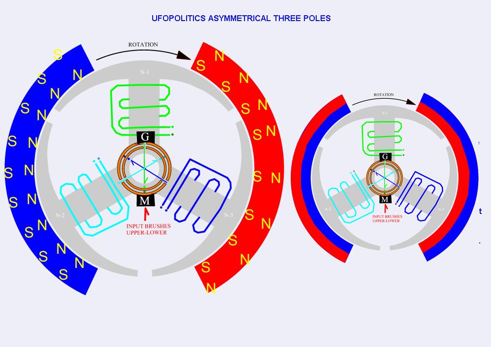
            • Convention for Drawing Magnetic Poles

              Hi All

              I had an email from a person who may be a newbie to how motors work.
              This has raised an interesting point regarding the drawing convention used to depict the magnet field of the stator, and maybe the convention should be changed.

              Referring to the diagram below, ‘to those experienced in the art’ will automatically know that the North pole refers to the inner polarity of the magnet, and the South pole likewise, we take it for granted the opposite poles on the reverse of the magnet.

              However, showing a North pole in blue, could also indicate we are looking at a North-pole face-on (this is where I think the confusion may have lay). Therefore as a suggestion would it not be better to depict the alignment of the magnets as they really are, as per the right hand drawing?


              Kind regards

              John

              Comment


              • Tape

                Originally posted by Vincevl View Post
                Hi John,

                My tach is IR and I did have a small piece of reflective tape on the shaft.
                I built my second motor and hope to make some tests soon.

                Cheers
                Vince
                Oh, Vince you just dashed my hopes of finding a no reflective tape tachometer into the ground. Kidding, it wasn't that important. I just never saw a reading without tape and was hoping no one was getting a bad reading by not using it or using it on an already reflective background. OK it's back to business as usual. Good luck with your motor tests.
                Thanks
                John Hav.
                Last edited by DadHav; 09-03-2012, 01:14 PM.

                Comment


                • Drawing Convention Used

                  John
                  As you and most of the rest of us know, the convention UFO has been using is an artist depiction of the functional poles. However as what we all want to happen, and that is that (every one), even the less experienced motor maker, be able to understand and make these motors without confusion, I can see that the convention change you propose would be help-full to many. Lets see what UFO thinks. UFO???????????
                  Any thing that makes less confusion is a good idea.

                  Dana
                  "Today's scientist have substituted mathematics for experiments and they wander off through equation after equation and eventually build a structure which has no relation to reality."
                  Nikola Tesla

                  Comment


                  • Originally posted by prochiro View Post
                    John
                    As you and most of the rest of us know, the convention UFO has been using is an artist depiction of the functional poles. However as what we all want to happen, and that is that (every one), even the less experienced motor maker, be able to understand and make these motors without confusion, I can see that the convention change you propose would be help-full to many. Lets see what UFO thinks. UFO???????????
                    Any thing that makes less confusion is a good idea.

                    Dana
                    Dana

                    Thanks.

                    @UFO: just to be clear - I'm not having a go at you! The way you draw is the convention - that's what I'm raising - my friend!

                    Regards

                    John

                    Comment


                    • Oh Vince!!

                      Hi John,

                      My tach is IR and I did have a small piece of reflective tape on the shaft.
                      I built my second motor and hope to make some tests soon.

                      Cheers
                      Vince
                      Originally posted by DadHav View Post
                      Oh, Vince you just dashed my hopes of finding a no reflective tape tachometer into the ground. Kidding, it wasn't that important. I just never saw a reading without tape and was hoping no one was getting a bad reading by not using it or using it on an already reflective background. OK it's back to business as usual. Good luck with your motor tests.
                      Thanks
                      John Hav.

                      Oh Vince!!..You just DESTROYED all my hopes to keep Dad Hav so busy... searching about this new concept of Tachometer without tape!!
                      Now all my hopes are completely vanished...

                      Well no...except Bob French!!..

                      But You were the main asset I had...cause of such tiny shaft...


                      Just kidding...


                      Regards to both of you


                      Ufopolitics
                      Principles for the Development of a Complete Mind: Study the science of art. Study the art of science. Develop your senses- especially learn how to see. Realize that everything connects to everything else.― Leonardo da Vinci

                      Comment


                      • Magnet Convention?

                        Originally posted by john_g View Post
                        Hi All

                        I had an email from a person who may be a newbie to how motors work.
                        This has raised an interesting point regarding the drawing convention used to depict the magnet field of the stator, and maybe the convention should be changed.

                        Referring to the diagram below, ‘to those experienced in the art’ will automatically know that the North pole refers to the inner polarity of the magnet, and the South pole likewise, we take it for granted the opposite poles on the reverse of the magnet.

                        However, showing a North pole in blue, could also indicate we are looking at a North-pole face-on (this is where I think the confusion may have lay). Therefore as a suggestion would it not be better to depict the alignment of the magnets as they really are, as per the right hand drawing?


                        Kind regards

                        John


                        Hi John!

                        Well you are right...we always use that convention and a newbie could think is a Monopole?...and if He can not find a Magnet that is ALL South...and a magnet that is ALL North...his motor would never , ever work?!...

                        I like the pattern on the right hand side...very well defined lines...


                        But, then I was that the experts may think My Machines will need specific magnet types... ...and that is the reason of their success?...


                        Regards


                        Ufopolitics
                        Principles for the Development of a Complete Mind: Study the science of art. Study the art of science. Develop your senses- especially learn how to see. Realize that everything connects to everything else.― Leonardo da Vinci

                        Comment


                        • Originally posted by Ufopolitics View Post
                          Oh Vince!!..You just DESTROYED all my hopes to keep Dad Hav so busy... searching about this new concept of Tachometer without tape!!
                          Now all my hopes are completely vanished...

                          Well no...except Bob French!!..

                          But You were the main asset I had...cause of such tiny shaft...


                          Just kidding...


                          Regards to both of you


                          Ufopolitics
                          Ha, Actually the search for the illusive tachometer made of Unobtanium is more of a distraction to some prime time I've been spending fishing, flying, boating and enjoying what will soon be the end of summer. I enjoy the fact there's some calmness and a little humor here now. I think it won't be long before UFO is calling people Dear again.
                          For now I'm remembering God gave us TWO eyes, TWO ears and ONE mouth.
                          Have fun everyone. Wind Um Tight.
                          John Hav.

                          Comment


                          • UFO,

                            OK. Last night I did as you asked (see below). I measured 5.2v running motor on linear feed and 4.2v on pulsed. With the pulsed I can reduce the heating, but the motor also will run slower, etc. When running the motor with linear feed I did not restrict the feed at all, but the PWM controller does reduce the feed even at "full power" setting. The input battery was 12.47v at rest, 12.35v under load.

                            My motor still won't output more than 11.6v with input of 12.5v. I rewound it with 30AWG bi-filar 16.5' long wires (instead of the single filar 30AWG 33' long). This gives the same amount of wire mass, but only .9 ohms. With the single 33' long wire I had 3.8 ohms. I think the ohms were too much and now too little. (?) Runs fast though...about 4005 rpm on 800mA of 12v (linear), and 7576 rpm on 24v (linear). 24v output is only 23.24v.

                            I placed the diodes as you show and lit a neon (NE-2) beautifully. Measuring after the diodes (on the neon side) I got .39v until the neon changed then it went up to between 1.4 and 2.2v. I noticed that the neon would last only so long then the white/purple would go away and the orange (which was much whiter than the usual orange) would be throughout the bulb. I was running the machine very slowly on PWM controller (measured 65 rpm at one point).

                            I couldn't stop there so I put a CFL on it and it would strobe very bright. I have posted pics (of my set up sprawled across the floor and the beautiful neon) on my Photobucket album (Pictures by bobfrench - Photobucket)

                            Boy! Ain't we hav'n fun!

                            Bob


                            Originally posted by Ufopolitics View Post
                            Hello Bob,

                            Yes those are the 550 Embodiment while the RS was the 250...

                            Now, your new Dual Pentagon should NOT get Hot...there must be something wrong there causing this to happen...
                            And Bob, I want you to take a reading there before you take it apart (I hope it is not too late by now..)
                            Set Your Positive Meter probe on the Battery Positive (Input) and your Negative Probe on the Negative of Output (the one right next to (+) Input above)...without adding the lower jumper between Positive Output-Negative Input...and see what it reads...

                            Then I want you to pulse it with your Oscillator...then do same readings on output...As you could set the diodes at output and connect the diode while pulsing it very low...like I showed on the diagram...and let Us know.


                            Thanks


                            Regards


                            Ufopolitics

                            Comment


                            • Hello Bob

                              Originally posted by bobfrench@fastmail.fm View Post
                              UFO,

                              OK. Last night I did as you asked (see below). I measured 5.2v running motor on linear feed and 4.2v on pulsed. With the pulsed I can reduce the heating, but the motor also will run slower, etc. When running the motor with linear feed I did not restrict the feed at all, but the PWM controller does reduce the feed even at "full power" setting. The input battery was 12.47v at rest, 12.35v under load.

                              My motor still won't output more than 11.6v with input of 12.5v. I rewound it with 30AWG bi-filar 16.5' long wires (instead of the single filar 30AWG 33' long). This gives the same amount of wire mass, but only .9 ohms. With the single 33' long wire I had 3.8 ohms. I think the ohms were too much and now too little. (?) Runs fast though...about 4005 rpm on 800mA of 12v (linear), and 7576 rpm on 24v (linear). 24v output is only 23.24v.

                              I placed the diodes as you show and lit a neon (NE-2) beautifully. Measuring after the diodes (on the neon side) I got .39v until the neon changed then it went up to between 1.4 and 2.2v. I noticed that the neon would last only so long then the white/purple would go away and the orange (which was much whiter than the usual orange) would be throughout the bulb. I was running the machine very slowly on PWM controller (measured 65 rpm at one point).

                              I couldn't stop there so I put a CFL on it and it would strobe very bright. I have posted pics (of my set up sprawled across the floor and the beautiful neon) on my Photobucket album (Pictures by bobfrench - Photobucket)

                              Boy! Ain't we hav'n fun!

                              Bob

                              Hello Bob!

                              Ok, one main question, before anything else here!!...did you use tape at shaft to Tach RPM's?...
                              But see you are "My only witness" that Laser Tach could read w/o tape...lol

                              Hey that is great!...You got the Radiant Glow...!
                              Now, you do have the brushes set as the diagram right?
                              Have you tried to adjust the timing by moving the brushes a bit?...That will help you to gain more output...
                              I did not read that you connected the Positive from battery and the negative from output, without jumping the bottom terminals?...See this two terminals are completely isolated without the jumper...and I wanted to know if you read voltage there.

                              7576 rpm on 24v (linear). 24v output is only 23.24v.
                              Man you are getting so much work [7567 RPM's (with or w/o tape??...lol) and I imagine a very high torque...] with only 0.76 Volts?

                              The only thing it should not do is heat up...did you check to see if any coils are grounded to
                              rotor?...

                              Keep having fun!!


                              Regards


                              Ufopolitics
                              Principles for the Development of a Complete Mind: Study the science of art. Study the art of science. Develop your senses- especially learn how to see. Realize that everything connects to everything else.― Leonardo da Vinci

                              Comment


                              • Other questions...

                                Originally posted by bobfrench@fastmail.fm View Post
                                UFO,

                                I rewound it with 30AWG bi-filar 16.5' long wires (instead of the single filar 30AWG 33' long). This gives the same amount of wire mass, but only .9 ohms. With the single 33' long wire I had 3.8 ohms. I think the ohms were too much and now too little. (?) Runs fast though...about 4005 rpm on 800mA of 12v (linear), and 7576 rpm on 24v (linear). 24v output is only 23.24v.`
                                Bob one question...Did you balance out the small coil to the bigger one on each Pair?
                                Like, if you had 16.5' total length on wire...so you used 8.25 for small coil and 8.25 for bigger one?

                                I placed the diodes as you show and lit a neon (NE-2) beautifully. Measuring after the diodes (on the neon side) I got .39v until the neon changed then it went up to between 1.4 and 2.2v. I noticed that the neon would last only so long then the white/purple would go away and the orange (which was much whiter than the usual orange) would be throughout the bulb. I was running the machine very slowly on PWM controller (measured 65 rpm at one point).
                                I see you are getting too small current on output (after diodes)...however, I saw the neon super purple glowing...so, could you compare at output Voltages before and after diodes...Voltages should be around "similar" values...

                                The other thing I wanted to tell you is...those Output V readings you are getting are not right...like I wrote before I showed a Snap On Tool (DC Adaptor) that will give you the true readings there...or a Scope...


                                Regards


                                Ufopolitics
                                Principles for the Development of a Complete Mind: Study the science of art. Study the art of science. Develop your senses- especially learn how to see. Realize that everything connects to everything else.― Leonardo da Vinci

                                Comment

                                Working...
                                X