I am dazzled again
Most impressive video my freind. Not only showing the test results but also your mastery of graphic design. I think this time you have put all doubts to rest. I hope the imperial will run with the same smooth vigor.
-
Leave a comment:
-
numbers from the video are
UFO post comparing uni-polar asym RS to std N-S RS are UN-FRICKIN'-BELIEVABLE!!!!


Now you really went and did it. Watch out for the men in black.
Motor volts RPM gen volts amps
NS 4.5 7816 1.6 1.19
NN 4.2 11267 2.9 0.77
NS 5.8 12000 2.8 1.12
NN 5.8 16800 4.4 0.82
NS 9.6 21000 5.3 1.31
NN 9.6 26000 7.7 1.13
OMG 44000 rpm at 12v!?!!!!!
At 9v input .3A no load, around 7v gen out noload.
Add a load at 1A, voltage ? out, volts in still 9v?, motor speeds up, 1Amp input.
A few more data points and that could be a really interesting calculation.Last edited by sampojo; 04-05-2014, 05:43 AM.Leave a comment:
-
WOW!!!
I'm ready for the Imperial!
Keep it Clean and Green
MidazLeave a comment:
-
G'day Cornboy
I started to watch and the quality is Very good but as it is so long I will have to watch it tonight
Regards KogsLeave a comment:
-
Hello UFO and all, thanks much for your video UFO, but now it comes up on
'real player" and the quality is so poor i can't even read the script, what the hell has happened to YOUTUBE???.
Do you have to pay now to have quality uploads??
Times they are a changing!!!
Regards Cornboy.
Leave a comment:
-
NN 20 Pole 2 stator rewind
Roger that, I just miscounted and I just thought it had to be that the last coil was small. My first effort had more counting errors. Here is my redo.Originally posted by Ufopolitics View Post
In your post you do seem to verify that I got the total number of poles correct according to your latest thoughts. I applied the ratio of the RS pole (3:5) to 20 poles to get 12 total per group and tried to copy the winding pattern of your quad stator diagrams of your 20 pole Bosch. I am close to finishing my comms.
So Ufo this pattern good to go? Brush positions right? (used RS brush locations)
No probs with where I need to start and end the group coil due to my comms needing the wire to come in at an angle on the connectors, as far as I can tell I hope.
So I am estimating various wrapping configs
19ga wire to come in at .2ohm at about 25'+/-3' per group
21ga wire to come in at .5ohm at about 40'+/-5' per group
my quadfilar 30ga to come in at 1 ohm at about 40' per group
Heating has always been an issue for my asym motors so I am leaning toward my quadfilar. You did not think the quad would be heavy enough in a previous post, but shylo is mentioning heating problems also, and lots of power (on partially wound machines?) You are indicating that a group resistance should be less than 1 ohm, so the quadfilar is right on the edge.
If you think it advisable to build a smaller prototype, I have a lot of 10-pole components around from car window motors. and I still have my QP10, (which lost a brush set, used solder to connect brush wires, easy fix I expect)Last edited by sampojo; 04-05-2014, 05:45 AM.Leave a comment:
-
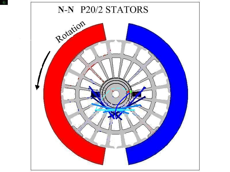
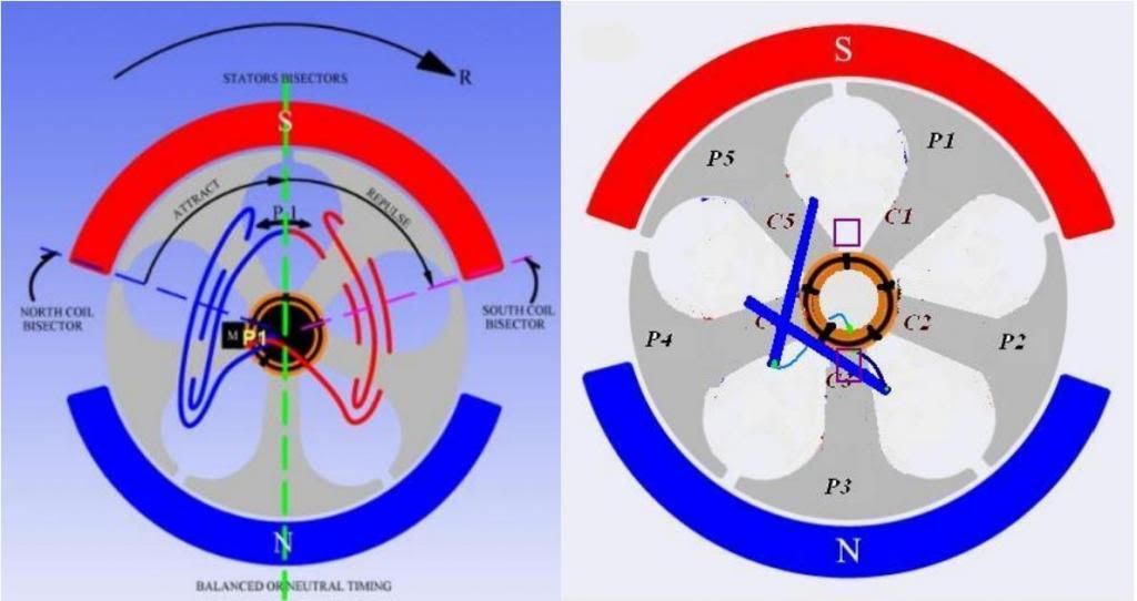
Five Pole Motor All North versus N-S Video...
Hello to All,
Well, I finished video...kind of long though, did not wanted to edit any of the testing parts...
https://www.youtube.com/watch?v=diY9...ature=youtu.be
I would like to go over in detail over this Data seen here later on guys...
However, main issue on the Difference in the Tests Results.
I did not wanted to comment about this differences till having the Full Video backing up My Words.
First, understand that I have utilized the same Motor Embodiment, same rotor, same casing, same magnets, same
wire awg and turns, resulting in exactly, same resistance per Pair...in order that the ONLY Difference between
the two Motors were the Geometry of its Rotor Coils...which delivers a very different magnetic field projection...
And the really amazing thing I see here...is the huge difference in performance between this Two almost identical
little machines...
This proven facts...should definitively confirm to all of Us...How Important it is to "see" and understand Magnetic Fields...and
how our Coils positioning will influence their projection into space...changing all results...for the success or for a failure...just have to find
the best way to fit our requirements...
Regards
UfopoliticsLast edited by Ufopolitics; 04-05-2014, 04:02 AM.Leave a comment:
-
Hello Brian and Welcome
Hello Brian and Welcome!Originally posted by brian516 View Post
Brian, back on July 10th 2012 (Tesla's Birthday...I've noticed that your work, and design is derived from the following Tesla patent.
Tesla Patent 390,721 - Dynamo-Electric Machine )...I uploaded ASYMMETRY TO ENLIGHTENMENT ...and if you go to minute 1:35...you would see on the background the whole Patent # 390721...plus all explanation related to such application...
You are welcome to start reading this Thread and joining Us...however, there is another one where I actually started this whole thing...before talking about Motors or Generators...the same patent that these crooks like QEG and WITTS are claiming to be basing their contraptions on, but the only people I see that are actually seriously working on the ACTUAL original Tesla designs and patents are you and this select group. I would very much like to join in. I still have quite a lot to learn, but unlike many others, my mind hasn't been thoroughly polluted by mainstream 'science' and the fallacies of Einsteinian Physics and like garbage, so I do feel that it would be worth it for me to apply myself to catching up with you all and getting involved. I don't want to be a 'leech', and I don't want to slow you all down in any way, so do expect me to put forth my utmost attention to learning to the best of my ability on my own, with some guidance, if you are willing to have me involved in this with you all.
I will need to start from page one of this thread and move thru at my own pace to absorb the info and do the work, so it'll be some time before I'm at the point where I'll be able to seriously contribute to advancing the knowledge, but I would very much like to try. I'm going to need to make some investments in equipment, too, and that I'm going to have to make the money to get. Since I will be starting fresh, if you wouldn't mind me joining in, I could apply myself towards whatever areas you find your group to be lacking in. Tesla was a very unique and complex minded man, so I'm sure there are plenty of things that would be useful to your project. For instance, the other components to the design shown in his patent, such as the exciter and transformer. The exciter is obviously the more complex of the two, so I could work on that, or the transformer then that, along with building one of your asymmetric generator/motors to compliment the exciter and transformer.
The main thing with me right now, is that I want to focus on Mr Tesla, and not spend my time piddling around with charging and making batteries and solar/wind generators... not that there is anything wrong with that... It just seems to me that you all have picked the most feasible/beneficial Tesla design to focus on, and I would like to be a part of it.
-Brian
http://www.energeticforum.com/renewa...nt-energy.html
Out of Tesla Patents...We gather a very "unique" attribute on his Machines..."Open Coils"...Pairs and Groups of INDEPENDENTLY ENERGIZED COILS...and from there we have derived into a completely different world of Electrodynamics...
Regards
UfopoliticsLast edited by Ufopolitics; 04-05-2014, 02:35 AM.Leave a comment:
-
I don't know a damn thing about electricity, but I'm looking to learn so I can fully understand what you doin here, Ufopolitics, one thing I know for sure, it's unique and works for what I've seen.
I just want an direction to what to study so I can do those beauty by my own, or if I only need to learn the principles of asymetric winding and voil�.
Now I have 03 dc motors(3V,5V and 2V) from an old dvd player, I believe they have 3 pole, I couldn't even open it yet, the metals are so hard.
So far I've read to page 06 of this topic and seems like there is enought information about 3 pole there, am I right?
+Vitor Ferr
P.S http://ufopolitics.com/ is not working in here.
20140404_230407.jpgLeave a comment:
-
Anyone working on the exciter part of the system??
Hey there UFO,
I've noticed that your work, and design is derived from the following Tesla patent.
Tesla Patent 390,721 - Dynamo-Electric Machine
the same patent that these crooks like QEG and WITTS are claiming to be basing their contraptions on, but the only people I see that are actually seriously working on the ACTUAL original Tesla designs and patents are you and this select group. I would very much like to join in. I still have quite a lot to learn, but unlike many others, my mind hasn't been thoroughly polluted by mainstream 'science' and the fallacies of Einsteinian Physics and like garbage, so I do feel that it would be worth it for me to apply myself to catching up with you all and getting involved. I don't want to be a 'leech', and I don't want to slow you all down in any way, so do expect me to put forth my utmost attention to learning to the best of my ability on my own, with some guidance, if you are willing to have me involved in this with you all.
I will need to start from page one of this thread and move thru at my own pace to absorb the info and do the work, so it'll be some time before I'm at the point where I'll be able to seriously contribute to advancing the knowledge, but I would very much like to try. I'm going to need to make some investments in equipment, too, and that I'm going to have to make the money to get. Since I will be starting fresh, if you wouldn't mind me joining in, I could apply myself towards whatever areas you find your group to be lacking in. Tesla was a very unique and complex minded man, so I'm sure there are plenty of things that would be useful to your project. For instance, the other components to the design shown in his patent, such as the exciter and transformer. The exciter is obviously the more complex of the two, so I could work on that, or the transformer then that, along with building one of your asymmetric generator/motors to compliment the exciter and transformer.
The main thing with me right now, is that I want to focus on Mr Tesla, and not spend my time piddling around with charging and making batteries and solar/wind generators... not that there is anything wrong with that... It just seems to me that you all have picked the most feasible/beneficial Tesla design to focus on, and I would like to be a part of it.
-BrianLeave a comment:
-
Great Work!
Hello Shylo,Originally posted by shylo View Post
Honestly, your contribution to our development here is very important and essential!
I have not got the chance to go into that stage of winding Groups yet...so, I will go by what you are saying till I can get to this end and confirm it.
So, you used a heavier gauge...may we know which one it was?
And which gauge was the finer one that worked out better?
We need to start establishing comparisons here my friend...but going into details...as also how many turns per coil on heavier Versus on finer...and could you take total resistance readings for both types?
I honestly do not understand your expression: "G1 & G11 are seeing the Identical magnetic field"...which magnetic field are you referring to?I wind 4 groups at the same time, one wire ,...a start,....and a finish, but they have a junction point in them.
In post # 6397 the 20 pole G1 & G11 are seeing the Identical magnetic field , so you can feed both groups together, as long as their wound the same , and fed the same.
Stator Magnetic Fields?...or Rotor Magnetic Fields?
I know we could feed both groups at same time, and that would "balance" rotation...I know also we could feed them Parallel or Series...BUT, we must do those connections Externally on Brushes wires...in order to test both results separately...
If You are using Fire Fox...while being on You Tube...go to Tools/Page Info>>>and at bottom of this window press "Details"/ then press "View Cookies" (will open another small window called "Cookies")...then press "Remove All Cookies"...at bottom centerAlso I haven't been able to watch video's since the u tube revamp.........
Restart Fire Fox...go to You Tube again...it should be fine now.
Agree, as I said before it also balances rotation forces.By firing G1 & G11 at the same time just balances out the draw better I think.
artv
Also I recommend you try slow rotation of different brushes positioning towards attraction poles (South)...while watching speed...it would tell you best timing "by ear"...
Regards
Ufopolitics
EDIT 1
Reviewing our post I realized what you have written above...I wind 4 groups at the same time, one wire ,...a start,....and a finish, but they have a junction point in them.
It means You are winding ALL this Four Groups in series, with same wire...just making a junction to drop at commutator elements?..so you are feeding them in parallel...ALL FOUR?!!...if that is so...then it is completely WRONG!
Shylo, how can you understand that every Group here is INDEPENDENT from EACH OTHER!...Winding them like you are doing...there is absolutely NO TIME OFF for any of those coils!!...they are ON at ALLl times!...that is why they get hot friend!...plus I wonder how this way it still runs?
You are just doing same exact way Symmetry Winding type does it...one wire and stops at every comm element hook, keep going to next coil...so on...WRONG!Last edited by Ufopolitics; 04-05-2014, 02:19 AM.Leave a comment:
-
Identical positions
Hi UFO & All, I've wound this 4 times , but only 8 groups, (I have room for 16 groups) things just get too hot. (I test each group)
With every wind , I went to a heavier guage wire, and things kept getting hotter.
Very fine guage ,with more turns per group is running like a champ.
I wind 4 groups at the same time, one wire ,...a start,....and a finish, but they have a junction point in them.
In post # 6397 the 20 pole G1 & G11 are seeing the Identical magnetic field , so you can feed both groups together, as long as their wound the same , and fed the same.
Also I haven't been able to watch video's since the u tube revamp.........
By firing G1 & G11 at the same time just balances out the draw better I think.
artvLeave a comment:
-
Wrong Groups Distribution...
Originally posted by sampojo View Post
Hello Sam,
Sorry but your design on your UNEQUAL SIZED COILS for the Blue Group...will deliver UNEQUAL Magnetic Fields...as also at time for Induction it will produce "jumping" different pulses at generating output.
Think about the magnetic fields...please.
When you make different sizes coils they will have different magnetic densities related to bigger coils...and bisectors will not be distributed EVENLY through circumference angles...
Every Coil in the Group, MUST wrap around EXACTLY same number of poles.
Regards
UfopoliticsLeave a comment:


Leave a comment: