Announcement

Collapse
No announcement yet.

My Asymmetric Electrodynamic Machines

Collapse
X
 
  • Filter
  • Time
  • Show
Clear All
new posts

  • Ufopolitics
    replied
    Excellent Post!

    Originally posted by marxist View Post
    Hi ufo,

    according to my current understanding, coil-group G2 will get energized - in the newly rewound 5-pole RS motor - before group G1 gets disconnected, due to overlap between brushes and commutator-elements. Then G3 will come ON before G2 gets disconnected and so forth.
    This means that the armature-field (the field created by the rotor-coils) remains constantly "in place" without ever collapsing.

    Is that important?
    Hello Marxist,

    Excellent post, I can see you are seeing the magnetic field rather than the physical connections...great!

    Well, the "constant field" from rotor is a typical phenomena that applies to every motor my friend...in our case we have an Asymmetrical Field related to Stators...while in Symmetry it sets exactly at 90º from Stators.

    But, referring to "Two Groups or Pairs" constantly at contact...it is not quite like that...analyze that commutator segments falls into the "junction" contact of Two Groups or Pairs with brushes at certain period only...while the other timing is dedicated to full element-brush contact...this also happened with previous winding type...so, it is not only applicable here.

    There is a way to shorten the contact times...and that is to move/rotate more one set of brushes relative to the other on top or bottom, wherever...achieving a more precise timing, after a "basic" one has been obtained...understand?

    [IMG][/IMG]

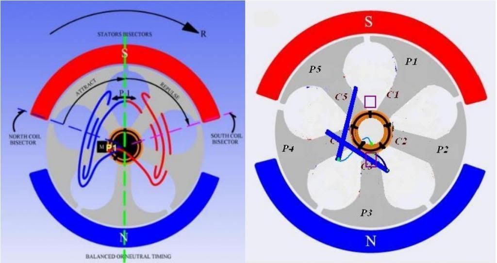
    The Diagram above I used it to correct some probable causes of malfunction...however, look at Left Diagram...and that is what am referring to, on my above comment...shortening the time of energizing by miss alignment between upper-lower brushes...I did it with both models I will present on video soon...

    If this is important, then using pulse duration to regulate the power of such motors may be problematic, because the field may collapse in between pulses (during OFF-time).
    It may be a better option to regulate such motors by regulating the applied voltage.
    !?

    Well, just thinking aloud and hoping not to offend or confuse anybody.
    That is correct...however, we could play with physical and pulses timing until they sync...

    Nope you are not confusing anybody...it is good to have this type of analysis, discussion ...


    Cheers


    Ufopolitics

    Leave a comment:


  • marxist
    replied
    armature field constantly present?

    Hi shylo,
    I hope it is not partly my fault that you wired the two opposing coil-groups in your 4-stator motor in series. I jumped to (wrong) conclusions and expressed them in a previous posting. Sorry, in case this influenced you.
    Now I know better.

    Hi ufo,
    according to my current understanding, coil-group G2 will get energized - in the newly rewound 5-pole RS motor - before group G1 gets disconnected, due to overlap between brushes and commutator-elements. Then G3 will come ON before G2 gets disconnected and so forth.
    This means that the armature-field (the field created by the rotor-coils) remains constantly "in place" without ever collapsing.

    Is that important?

    If this is important, then using pulse duration to regulate the power of such motors may be problematic, because the field may collapse in between pulses (during OFF-time).
    It may be a better option to regulate such motors by regulating the applied voltage.
    !?

    Well, just thinking aloud and hoping not to offend or confuse anybody.
    Last edited by marxist; 04-03-2014, 09:38 AM.

    Leave a comment:


  • sampojo
    replied
    NS vs. NN 5-Pole comparison

    So I thought I would do a side by side comparison of the 2 windings:


    Extrapolating to a 20-pole Dual Stator machine like my Baldor by combining the technique of the Bosch, a coil group would contain 12 poles, since there are 3 poles out of 5 in the RS style armature, times 4 for a 20-pole?
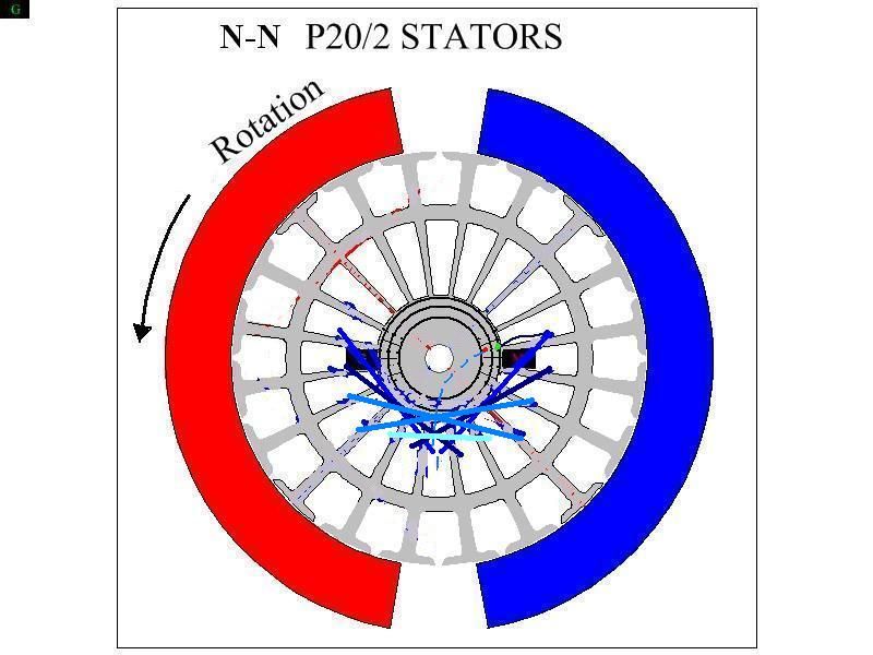
    So Ufo, how's this look for my Baldor? (EDIT: OOPS, engaging 13 poles in the group. Move everything over one pole and throw out the last odd single sub-coil!!! AND no crossing of sub coils, must be like the Bosch with a gap between sub groups?) EDIT: Fixed! Winding looks complex operation. Same number of wraps on each sub-coil?


    EDIT: Diagram INCORRECT, pole counts wrong on several sub groups!

    I am not sure if I can read the imperial and Bosch diagrams quite right, but the video definitely has the comm segments lined up with the poles (as opposed to the pole-holes )

    My connector commutator design needs the wire to come in across the shaft a bit. I think this winding has barely enough of an angle of attack on the side with the green dot. Maybe just take out a half wind and come across the shaft that way.

    So my baldor used 19ga. Did I read recommendations to use 25' of wire per group for the imperial? Ufo, it seems you may be leaning toward holding the line toward the heavier gauges now as opposed to going to a higher gauge with the N-S style? I am thinking about the same length for the baldor might work, so just use whatever gauge gets me to 1 ohm per group? I sorely want to use my quad-filar, going for every advantage... I think it will have about .7 ohm resistance per 25', maybe get a little more length since its nominal diam. is around a 21ga.

    Progress on my commutator: 13 connectors installed on last comm, 7 remaining components have been manufactured. should be a matter of hours to install them, then ready to wind. ( that is in hours of free time, which I wont have any now for days, just some on the weekend.)
    EDIT: 4 more to install.
    Last edited by sampojo; 04-05-2014, 03:39 AM.

    Leave a comment:


  • iankoglin
    replied
    Kogs Nessie's update

    G'day All
    I am having a bit of trouble with my controller it is the Oscillator the one I am was using had a 50K ohms pot everything went OK
    Now I want to use this controller with either UFO's or J Stone's monster to run the Modded 1000w Chinese motor the Magura twist throttle is a 5Kohms Pot and I modified my oscillator by changing the two 1k ohms resistors to each leg of the pot to 100 ohms and the 2 caps from 0.01uf to 0.001uf and it works OK until it just stops I change the 555 chip and it immediately seems to blow I check with a special chip tester and it shows OK I try again it wont work I put a new 555 chip in it wont work I made a new Oscillator it has the same problem

    Garry from Chemelec said that the 555chip can not work with 100 ohms here I need to increase the ohms to 330 or 450 ohms but the duty cycle will not be 1 to 99%
    I need an oscillator that does not use a 555 chip one with a 5K input OR
    a twist throttle that is 50K ohms of which I have not been able to find one

    Please can anyone here help me

    Kindest regards

    Leave a comment:


  • Ufopolitics
    replied
    Groups and Pairs differences

    Originally posted by shylo View Post
    Hi UFO, I did connect the 2 groups in series, actually wound them .
    Hello Shylo,

    I figured that...not good...each Group is INDEPENDENT from each others.

    Before We did Pairs, which were Two Coils projecting a North and a South adjacent to each others...

    Now, in larger poles machines ( not Three, Not Five) we are using Groups that are ALL WOUND CW, meaning all same magnetic Polarity.


    Also To Everybody, I made a mistake , there are only 4 coils per group ,so 20 turns per group 40 for group pair.
    You need to do better than that, meaning MORE Than Five Turns per Coil, then measure resistance per Group...and you must be over 0.7 ohms...more likely 0.9 to 1.0 ohm.

    What gauge wire (awg) are You using?

    If the coils of 1 group are 180 deg. opposite the coils of #2 group in a 4 pole stator they are both in identical positions.
    "Both Groups in Identical positions"?...One Group is interacting with Two Stators at , say left side...while other Group is Interacting with OTHER TWO Stators at right side...while both Groups are projecting South towards the center shaft area...

    I really do not see any "identical" properties between these two Groups...

    So I don't understand your concern....Does only 1 group get fired at a time?
    YES!...Each Group Fires Independent from each others...so we could select just to fire one side, one set of brushes...while other Three Gates are used as Generators...or we could add Four Monster Pulsers and run each Gate at different progressive timings...understand?

    My Concern is that I do not believe you got this right...yet

    Yesterday you were running your 18 Poles Motor First, with just two Groups...then you added at 90º two more groups, and tried to run it again...that is wrong Shylo.

    Your 18 Pole Rotor MUST HAVE 18 Groups Total...Continuously wound, One after the other...overlapping each Group with the next...sharing common Coils except ONE (One ahead) Each Group must go to two commutator elements above and below...so the next one...BUT NOT TWO, NOT FOUR GROUPS ONLY!!...then of course you are gonna have lock ups...and all kind of weird responses...because Rotor is NOT running with FULL Groups wound/connected...so its Motoring Force is smaller/weaker than the Self Induced or CEMF Forces...then it tends to lock...

    Like I said I'm not even sure I'm doing this right.
    Sorry about the mistake folks, I don't know what I was thinking.
    artv
    It's Ok...You will "get it" right...


    Reagards and let Us know, please!


    Ufopolitics

    Leave a comment:


  • shylo
    replied
    Originally posted by Ufopolitics View Post
    Hello Shylo, good work friend!

    Now, it worries me you keep calling this Two INDEPENDENT GROUPS ..."Pairs"...?...I hope you are not connecting them in series between each other


    Regards


    Ufopolitics
    Hi UFO, I did connect the 2 groups in series, actually wound them .
    Also To Everybody, I made a mistake , there are only 4 coils per group ,so 20 turns per group 40 for group pair.
    If the coils of 1 group are 180 deg. opposite the coils of #2 group in a 4 pole stator they are both in identical positions.
    So I don't understand your concern....Does only 1 group get fired at a time?
    Like I said I'm not even sure I'm doing this right.
    Sorry about the mistake folks, I don't know what I was thinking.
    artv

    Leave a comment:


  • Ufopolitics
    replied
    All North Rs

    Originally posted by warrensk View Post
    Right on guys!

    I have been checking in steadily, good to see you guys making some progress....Ive got a RS 5 pole...The homopolar idea looks promising...As faradays homopolar generator supposedly was capable of a self sustaining current with modifications by tesla...This played some important parts in his turbine idea as well...

    Anyways, I will do a RS 5 pole replication and compare it to the pentagon winding which I have laying around somewhere...Ive also got a 20 pole 1000W MY1020 motor still chillen. This new design looks promising...Can't wait to test it out!

    @UFO

    So this new homopolar design has "groups" of coils instead of pairs....? Is this wound the same way as the pairs except both windings are same direction? When I do the RS replication I suppose I will answer a lot of my own questions...

    warrensk

    Hello Warrensk, great to see you back!!

    I made this short video...good luck seeing it..terrible quality on "New You Tube"..

    Edit: All errors on You Tube were due to Navigator Errors...no problem with video, no sound on this video.

    http://m.youtube.com/watch?v=RSs2beN...ient=mv-google

    just to see the 3D CAD Animated Camera around Whole Coil/Core...it is quite different from previous Typical P5...

    Brushes are set like they were on Original Symmetrical...meaning at 90º to Stator Gap Line

    Plus All Coils are CW...


    Regards


    Ufopolitics
    Last edited by Ufopolitics; 04-02-2014, 04:03 AM.

    Leave a comment:


  • Ufopolitics
    replied
    Good job Shylo!

    Originally posted by shylo View Post
    Hi All, The attached is my attempt at 16 pole.
    I wound two groups (a pair) , with each group having 8 coils 5 turns per coil , so 40 turns per group , 80 turns in the pair.
    I tested the pair of groups and it ran quite well. But just hooked the start and the end on one comm.
    I then wound the 2nd group 90 degrees offset from the first, added the second comm. ...so the starts of the 2 groups attached to the motor comm. ,and the 2 ends of the groups tied to the 2nd comm.
    So really four single groups, (room for 12 more).
    It ran very fast ,but as it ran my meter was showing the battery voltage going up.??? But when I disconnected the voltage dropped , but like UFO said the motor continues to spin for a couple seconds. strange.
    Still not sure if I'm doing this right but it seems to be working.
    artv
    Hello Shylo, good work friend!

    Now, it worries me you keep calling this Two INDEPENDENT GROUPS ..."Pairs"...?...I hope you are not connecting them in series between each other?

    Remember each Individual Group here is taking the place of what used to be a "Pair" of Coils.

    And yes, the Induction would be greater on this type of winding...so make sure that the CEMF is aligned to act/start as Repulsive Fields by passing Stators Bisectors right after disconnect...and not locking up rotation.

    More strange things coming up...


    Regards


    Ufopolitics

    Leave a comment:


  • shylo
    replied
    Groups

    Something strange happens when you add more groups, the magnetic field of the coils you are inducing changes ,in relation to the coil that has just fired, 90 degrees away.
    I added 3& 4 group pairs , It creates severe lock-up, when it should not.
    Melted leads , and lots of smoke.
    I think the collapsing field of the coil that just left ,..power-on....is inducing the on-coming coil that is to be powered.
    I'm gonna remove 3 & 4 and run again.
    UFO have you noticed this??
    artv

    Leave a comment:


  • shylo
    replied
    Groups pairs

    Hi All, The attached is my attempt at 16 pole.
    I wound two groups (a pair) , with each group having 8 coils 5 turns per coil , so 40 turns per group , 80 turns in the pair.
    I tested the pair of groups and it ran quite well. But just hooked the start and the end on one comm.
    I then wound the 2nd group 90 degrees offset from the first, added the second comm. ...so the starts of the 2 groups attached to the motor comm. ,and the 2 ends of the groups tied to the 2nd comm.
    So really four single groups, (room for 12 more).
    It ran very fast ,but as it ran my meter was showing the battery voltage going up.??? But when I disconnected the voltage dropped , but like UFO said the motor continues to spin for a couple seconds. strange.
    Still not sure if I'm doing this right but it seems to be working.
    artv
    Last edited by shylo; 04-11-2014, 09:04 PM.

    Leave a comment:


  • warrensk
    replied
    Right on guys!

    I have been checking in steadily, good to see you guys making some progress....Ive got a RS 5 pole...The homopolar idea looks promising...As faradays homopolar generator supposedly was capable of a self sustaining current with modifications by tesla...This played some important parts in his turbine idea as well...

    Anyways, I will do a RS 5 pole replication and compare it to the pentagon winding which I have laying around somewhere...Ive also got a 20 pole 1000W MY1020 motor still chillen. This new design looks promising...Can't wait to test it out!

    @UFO

    So this new homopolar design has "groups" of coils instead of pairs....? Is this wound the same way as the pairs except both windings are same direction? When I do the RS replication I suppose I will answer a lot of my own questions...

    warrensk

    Leave a comment:


  • Midaztouch
    replied
    @Team

    I don't know if you have noticed but this thread has moved in to second position for the most views!


    UFO, keep up the great work and hope to see a million this year! Awesome

    Congratulations

    Keep it Clean and Green
    Midaz

    Leave a comment:


  • interestedngreen
    replied
    finally got it

    I appreciate the welcome from the guru himself, Mr. Ufopolitics. And thank you very much for the answer to my 5 pole winding question. Your illustration where the coils overlap, and as you specifically mentioned, clarified the new winding process for me. Just to report, as I anticipated that it will perform even better than the P-# method of winding, I mounted my new motor with a pair of bearings on each end. And does it take off when I power it on? Makes me more excited for this new method of winding used in a UFO Kit. Please know, Mr. Ufopolitics how much I appreciate what you are doing in this forum, your long hours working on the technology you are exposing us to, all the effort you put in laying out for us who want to learn at your feet and most of all the knowledge that you freely impart to us. Thank you very much and more power to you.

    Leave a comment:


  • Ufopolitics
    replied
    Originally posted by sampojo View Post
    Ufo, are you saying that the RS based 20 pole bistator winding then will be the same as for the Bosch 20 quadstator?
    Hey Sam,

    Nope, I never said that...You asked before for a way to add some coils in the empty spaces for your Baldor, when doing it like a RS Five Poles...

    I notice your Bosch 20-pole has 9 poles per group, but you implied earlier the RS based 5-pole design upleveled to a 20-pole bistator motor will still hold to a basic 8-pole group? Things still in flux there?
    Sam, You talked about the Eight Poles when we were referring to PAIRS...not Groups.
    You have 20 Poles, winding by 5 Pairs, each pair will have eight (8) poles...each coil will have 4 poles then...

    If I look at a the quad, the 9-pole group is dealing with one stator.
    Negative...look again, the 9 pole group G1 is "dealing" with North Stator (Repulsion) and South (Attraction)...and so is the Group G11 with the other two stators...

    Would that logic on a bistator mean that group would deal with 15 poles?
    Say whaaat??...

    In a Bistator the Interaction N-S Repulse-Attract takes place also, between the two stators...at either end of Gap.

    Are the bisector limits essentially the 90 degree arc between the N & S Pole of the Bosch stators? Or is the bisector limit the number of poles subtended by a stator? I think the Baldor has 8 there...
    That is correct, the Bisector Limits are defined by the 90º Arc between each N-S Stators CENTER..or bisector.
    The number of poles that you will build Group with...will depend, of course, on "fitting" within that 90º Angle...BUT leaving a GAP to play with timing...so IT CAN NEVER BE EXACTLY 90º.


    So will the groups end up focussing the North pole or make it a bit diffuse? What if the internal coils of a group were concentric instead of overlapping?
    Concentric you mean for each pole One coil?

    The rule of thumb on Motor Coils size be determined by the size of the Stator or permanent magnet Arc..more or less. This way the Magnetic Field is around the size of Stator, therefore, Bisectors encountering at similar angles...so Concentric Coils (per pole) will not work at all with bigger sized stators.

    The overlapping of coils maintains Magnetic Fields also "Overlapped"...therefore, stronger than Individual Coils, not overlapped.
    Overlapping allow Us to use more wire, cause we have more room or slots to spread wires at...

    I can't tell which group hooks to which brush set in the diagrams very well...

    I feel like the kid who asks too many questions. NP I wait for a diagram then.
    Is ok, good questions Sam...will serve to others learning and reading this Posts...

    EDIT: OK I was confused at first by the G1 group vs the G1 Generator brush designation, but I think I see it now.
    Great...

    So these coils are just going to fire briefly near the point of max repulsion from N stator and max attraction from S stator at/near midpoint of the gap between stators?
    Nope...but you have the whole concept correct though...

    This Coils will fire CLOSER to the Repulsion Stator (North in this types).THAN to the Attraction Stator (I wrote this before here on the previous Imperial Pair all north...)

    You must realize a repulsion is a "push force" applied to rotor, pushing it AWAY..without limits...while the Attraction is a limited Pull reaction till it reaches the "lock up" of both bisectors or Field Alignment...then Motor would tend to heat up or rise amp draw to top limits, (even by being Too Close to this Lock Up Point) So, you must always leave the bigger angle gap towards attract stators, meaning, killing power to coils through your brushes alignment...considering the speed this motors would travel at...

    Therefore, it is very important to check at commutator element leaving contact with brush (All Coils Off)...while observing that Coil Groups FIRST COIL is not too close nor passing the Attraction (South) Bisector or dead center of stator.

    Yeah, I referred to high speed because with acceleration and inertia forces will carry heavy magnetic reminiscence to the lock up zone...not good.


    Is there a delay before the bemf kicks in. Looks like that is going to instantly fight the rotation...
    Don't worry...I told her to leave Us alone...

    BEMF should kick in AS SOON AS Group Passes South Stator Bisector...but remember that Groups also Overlap between them...


    Take care


    Ufopolitics
    Last edited by Ufopolitics; 03-31-2014, 08:02 PM.

    Leave a comment:


  • sampojo
    replied
    RE: So...Let's do Groups instead of Pairs...

    Originally posted by Ufopolitics Post 6397 View Post
    Now...this answers your question Sampojo...About having Eight(8) Poles Per Pair...so Now You could figure GROUPS...BUT REMEMBER...Groups MUST stay within Bisector Limits...
    .
    .
    .
    Still working on Five Pole Video...
    Ufo, are you saying that the RS based 20 pole bistator winding then will be the same as for the Bosch 20 quadstator?
    I notice your Bosch 20-pole has 9 poles per group, but you implied earlier the RS based 5-pole design upleveled to a 20-pole bistator motor will still hold to a basic 8-pole group? Things still in flux there?

    If I look at a the quad, the 9-pole group is dealing with one stator. Would that logic on a bistator mean that group would deal with 15 poles?

    Are the bisector limits essentially the 90 degree arc between the N & S Pole of the Bosch stators? Or is the bisector limit the number of poles subtended by a stator? I think the Baldor has 8 there...


    So will the groups end up focussing the North pole or make it a bit diffuse? What if the internal coils of a group were concentric instead of overlapping?

    I can't tell which group hooks to which brush set in the diagrams very well...

    I feel like the kid who asks too many questions. NP I wait for a diagram then.

    EDIT: OK I was confused at first by the G1 group vs the G1 Generator brush designation, but I think I see it now. So these coils are just going to fire briefly near the point of max repulsion from N stator and max attraction from S stator at/near midpoint of the gap between stators? Is there a delay before the bemf kicks in. Looks like that is going to instantly fight the rotation...
    Last edited by sampojo; 03-31-2014, 06:42 PM.

    Leave a comment:

Working...
X