Announcement

Collapse
No announcement yet.

My Asymmetric Electrodynamic Machines

Collapse
X
 
  • Filter
  • Time
  • Show
Clear All
new posts

  • sampojo
    replied
    Reply to UFO about Baldor/ what about multifilar

    Originally posted by Ufopolitics View Post
    Hey Sam,

    Well, look at it this way...it is a good thing you are still on this stage...and have NOT wound your BALDOR...

    Now, for sure we will make it roar...!!

    Was it a 20 or a 40 Poles?...I believe Comm is 40 elements...and it is a 20 right?


    Regards


    Ufopolitics

    Si! 40 elements on com, joining 2 ea. to make 20, One doubled comm segment per pole. I had prepared a quadfilar from my stock of 30ga, if memory serves me, and was planning approximately a 21-22ga winding.

    So multifilar still better than single wire coil, right UFO?

    I am trying to imagine what the CAD wiring dgm. would be for the 20pole bistator Baldor. As you point out on the new imperial winding, a coil subtends the number of poles needed to fit the magnet width. With just the the 2 stators, looks like about 8 poles on a coil for a 20 pole, something like that?

    Here is my progress on my comm dremmel-out wire problem. I just could not see how I could make those slots work since they did not seem to be able to be wired like a new imperial comm and the wires would stay in.

    The one on the right I am reusing the old wires, left is reinserting and stamping a Y-type brass connector, brazed together. I am using 14ga wire there. When fitted well into the slot and stamping, just barely enough copper left to make it so solid it feels welded. whew! I always am getting caught up on the material redesign of things.

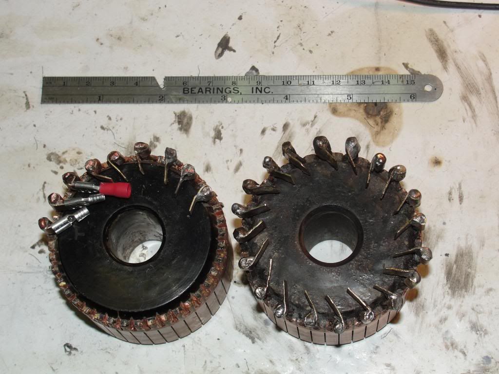

    You can see how nice things look on the stamp job here. (Or should I say functional?)
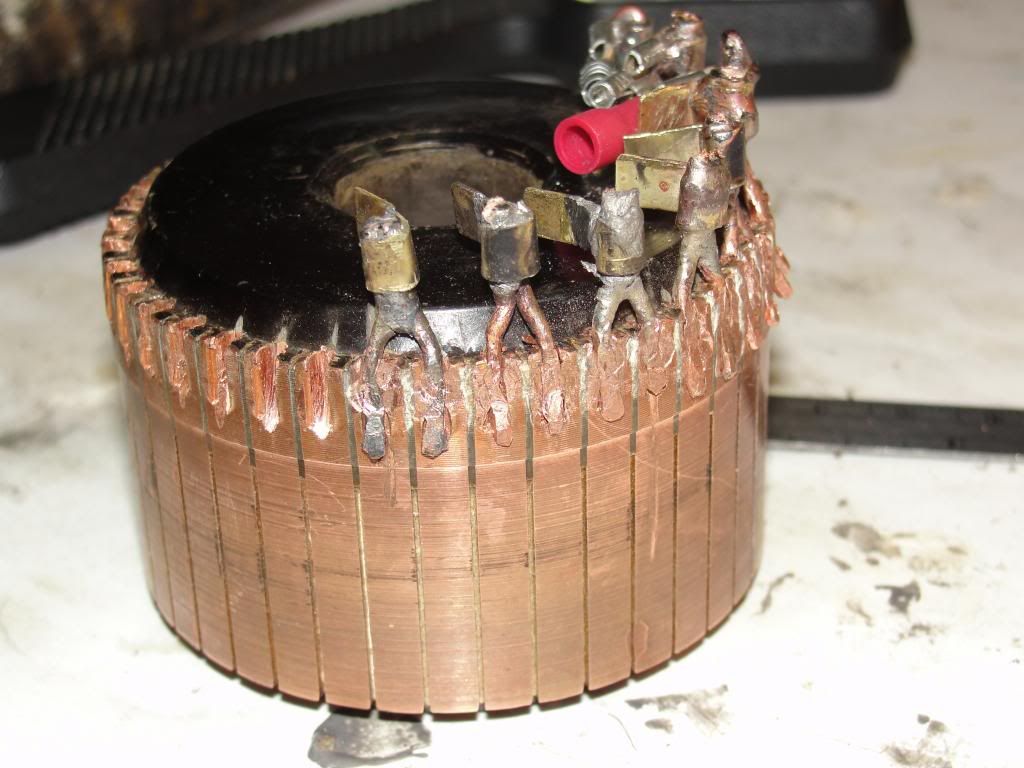


    Baldor is real roomy on the comm-shaft distance, so not too worried about coil crossover buildup...

    Woohoo can't wait to get started on winding, Oh well back to taxes, car probs, new hip, etc.
    Last edited by sampojo; 03-29-2014, 03:07 PM.

    Leave a comment:


  • iankoglin
    replied
    Originally posted by interestedngreen View Post
    I have been following the posts here silently in the sidelines. I have been winding 3 & 5 pole motors; mostly work on the 5 poles because the 3 pole motor is so small. I have successfully wound a couple of 5 pole which pictures I will upload shortly. I have worked on these I call screamer because it spins like it's ready to explode with only 12V. I feel I am ready to move to the next level. So, I ordered my first UFO Kit and wires. I just received them and I am ready to start winding. However, I do not know yet if I want to wind it using the P-# method or use the latest way that Mr. UFO just disclosed here. The reason was I went back and rewound one of my 5 pole twice; 1st winding it CW but when I ran the motor, it was producing a lot of heat. Then I disassembled and rewound, this time, CCW and ran it. It too was heating up. Perhaps, someone can clarify for slow learners, like me, how this new method is done. I appreciate very much the knowledge that has been shared here, especially and foremost to Mr. Ufopolitics. By the way, I am new to winding motors but always a fascination on building my own. Again, thank you very much to the team members who contributed to this excellent forum with Mr. Ufopolitics at the helm.
    G'day interestedngreen
    Welcome here its good to have others who are interested and really try to replicate what UFO has disclosed to us.

    I would hang off for a while before attempting to wind the Imperial as UFO has not as yet really determined how it should be wound and he is the expert on these things. He will later show us how to wind it and if you read or rather re read his latest info on the Imperial P56 he did say hold off until he does his own tests and he will later do some exact drawings showing us where to connect the windings to the brushes

    This is very important to understand if you take a look at my drawings that I posted a few days ago you can see that both drawings are the same motor and it is important to understand where the P1 (standing for the centre of Pair1) position is in relation to the brushes and the Stator magnets notice the centre lines for the stator magnets and the centre lines for P1 N and P1 S and also notice where the Brushes are in relationship with the commutator segments study these 2 drawings

    http://www.energeticforum.com/251392-post6261.html

    When you have done this please post me what the difference is between the 2 drawings

    when I first modified the small Tandy motor I really could see some action with it and as I tried all sorts of things I actually nearly blew the thing up and it does not run so well now the reason these little motors have been built to run at the speed they are designed for and they are only supposed to have a certain volts/current applied and we get so excited when we get these little motors going way past their expected specs I we treated our kids the same way they would throw us in jail and throw away the key.
    as far as the heating up goes I can not say perhaps after when you post me the difference between the two drawings we could discuss further.

    Kindest regards


    Kogs just trying to be helpful

    Leave a comment:


  • Midaztouch
    replied
    Originally posted by interestedngreen View Post
    Hello Midaz,

    Thank you very much for your reply. The particular motor I rewound to try the latest winding method Mr. Ufopolitics explained is a printer motor. I used the same wire that was in it when I rewound it and I believe it is a 26 ga. Each half of the coil is 30 turns. I guess, my wondering resulted from the fact that when I wound it using the P-# method and ran, it ran really fast but no heat despite running it for as much as 45 minutes at one time. And I did not get the same result as when I rewound it with just either CCW or CW only. Probably, I will run it with bearings on the shaft and see if that reduces the heat. Also, I've been trying to upload the pictures of my modified motors but that is a work in progress. I can not get the pictures out of my cell phone. Thanks again.
    Interestedngreen

    When running all ccw or cw, where was your source(s) of heat? Did the motor sound like it was running smoother? Was the rpm a slight or major decrease?

    Remember, UFO used the same gauge wire and turns in the all cw windings as the original 5 pole winding.

    Using a smart phone to down load pics should be fairly easy. If not, try using photobucket to store your pics for downloading.

    Keep it Clean and Green
    Midaz
    Last edited by Midaztouch; 03-29-2014, 06:15 AM.

    Leave a comment:


  • interestedngreen
    replied
    thanks for the reply.

    Hello Midaz,

    Thank you very much for your reply. The particular motor I rewound to try the latest winding method Mr. Ufopolitics explained is a printer motor. I used the same wire that was in it when I rewound it and I believe it is a 26 ga. Each half of the coil is 30 turns. I guess, my wondering resulted from the fact that when I wound it using the P-# method and ran, it ran really fast but no heat despite running it for as much as 45 minutes at one time. And I did not get the same result as when I rewound it with just either CCW or CW only. Probably, I will run it with bearings on the shaft and see if that reduces the heat. Also, I've been trying to upload the pictures of my modified motors but that is a work in progress. I can not get the pictures out of my cell phone. Thanks again.

    Leave a comment:


  • Midaztouch
    replied
    Originally posted by interestedngreen View Post
    I have been following the posts here silently in the sidelines. I have been winding 3 & 5 pole motors; mostly work on the 5 poles because the 3 pole motor is so small. I have successfully wound a couple of 5 pole which pictures I will upload shortly. I have worked on these I call screamer because it spins like it's ready to explode with only 12V. I feel I am ready to move to the next level. So, I ordered my first UFO Kit and wires. I just received them and I am ready to start winding. However, I do not know yet if I want to wind it using the P-# method or use the latest way that Mr. UFO just disclosed here. The reason was I went back and rewound one of my 5 pole twice; 1st winding it CW but when I ran the motor, it was producing a lot of heat. Then I disassembled and rewound, this time, CCW and ran it. It too was heating up. Perhaps, someone can clarify for slow learners, like me, how this new method is done. I appreciate very much the knowledge that has been shared here, especially and foremost to Mr. Ufopolitics. By the way, I am new to winding motors but always a fascination on building my own. Again, thank you very much to the team members who contributed to this excellent forum with Mr. Ufopolitics at the helm.
    Hello Interestedngreen

    I've been reviewing the beginning pages, 10-50. The 3 & 5 pole are to get you familiar with winding asymmetrically. The brushes are cheap and may need time to "seat", low speed bearings, poor alignment and using overvoltage, causes a lot of heat. UFO had also mentioned that those motors should be pulsed.

    Please tell us the wire gauge and how many winds per coil? That way, the people that have winded the 5 pole can give you solid advice.

    The new wind geometry for the Imperial is for me.

    Let's wait and review the test vids that UFO is making for the 10 pole. Maybe it can give us some hints for the Imperial

    Keep it Clean and Green
    Midaz

    Leave a comment:


  • interestedngreen
    replied
    post only now but been in the fences all this time

    I have been following the posts here silently in the sidelines. I have been winding 3 & 5 pole motors; mostly work on the 5 poles because the 3 pole motor is so small. I have successfully wound a couple of 5 pole which pictures I will upload shortly. I have worked on these I call screamer because it spins like it's ready to explode with only 12V. I feel I am ready to move to the next level. So, I ordered my first UFO Kit and wires. I just received them and I am ready to start winding. However, I do not know yet if I want to wind it using the P-# method or use the latest way that Mr. UFO just disclosed here. The reason was I went back and rewound one of my 5 pole twice; 1st winding it CW but when I ran the motor, it was producing a lot of heat. Then I disassembled and rewound, this time, CCW and ran it. It too was heating up. Perhaps, someone can clarify for slow learners, like me, how this new method is done. I appreciate very much the knowledge that has been shared here, especially and foremost to Mr. Ufopolitics. By the way, I am new to winding motors but always a fascination on building my own. Again, thank you very much to the team members who contributed to this excellent forum with Mr. Ufopolitics at the helm.
    Last edited by interestedngreen; 03-29-2014, 02:48 AM. Reason: correction

    Leave a comment:


  • Ufopolitics
    replied
    Split Coils

    Originally posted by GChilders View Post
    @ufoPolitics
    I believe that a simpler geometry might be tried, such as the 3 pole where as each pole is powered there is opposition from both poles interacting with the same poles. I am not sure how much influence the structure of the rotor has on the magnetic field. I am sure that there is influence but you are right in that the nature of the change may be a little unpredictable. Have you tried winding the ten pole with a single coil instead of a split coil for each pole?? Just an idea that mimicks the simplicity of the 3 pole.

    Cheers,

    Garry
    @Garry

    You are right, we should study further simple Geometries ...

    The purpose of the Split Coils is to widen the Interaction, meaning, creating Two Bisectors one per coil, in order to use one against South and the other to North of the Stators, based on Dual actions...repulse-attract...then we get a more robust throw out force by using just one coil input.

    I have wound a 12 pole as a Three Pole (12/3=4 Pole per coil)...too crazy of a machine...tons of power, weird effects...but I used 18 awg though...

    Regards


    Ufopolitics

    Leave a comment:


  • Ufopolitics
    replied
    Originally posted by Midaztouch View Post
    UFO


    Could you please expand more on the "Effect" is not there." for the 10 pole?

    Keep It Clean and Green
    Midaz
    Hello Midaz,

    Effect referring to the Ground Radiant Effect I got on the Three Pole. Plus the Amp draw is not that low either as in the Five Pole new wind...However, when I jump rear connectors and feed two front like we all have been doing...it does the Effect...plus I can light up an incandescent bulb and RPM's will not get affected.


    I am gonna make a video to show all this...but am not done yet.


    Be patient...


    Regards


    Ufopolitics

    Leave a comment:


  • Midaztouch
    replied
    UFO

    It is about the way you are "Projecting" that Coil North or South Garry...if coils have same Input +/- they will always project same N or S, so it depends upon the position related to Stators and the way current flows...

    But there is more about the Three Pole...I just finished a P10 all North at rotor...and somehow the "Effect" is not there...

    So, yes, we may be on the right track here...but we still have to keep testing...
    Could you please expand more on the "Effect" is not there." for the 10 pole?

    Keep It Clean and Green
    Midaz

    Leave a comment:


  • GChilders
    replied
    magnetic penetration

    @ufoPolitics
    I believe that a simpler geometry might be tried, such as the 3 pole where as each pole is powered there is opposition from both poles interacting with the same poles. I am not sure how much influence the structure of the rotor has on the magnetic field. I am sure that there is influence but you are right in that the nature of the change may be a little unpredictable. Have you tried winding the ten pole with a single coil instead of a split coil for each pole?? Just an idea that mimicks the simplicity of the 3 pole.

    Cheers,

    Garry

    Leave a comment:


  • Ufopolitics
    replied
    Three Poles...

    Originally posted by GChilders View Post
    @ufoPolitics

    After examining the new radio shack wind I am baffled. We are again splitting the wind into two different poles. I think what made the three pole so powerful was that the poles did not interfere with each other.
    Hello Garry,

    You are completely right...in the new RS Motor after the new winding runs excellent, much better than before with the prior winding.

    The 3 Pole have independent single Coils, all facing North towards Stators, then all South toward shaft...however, just one Pole at a time gets activated/fired, while the other two are "idling" or at Generator Stage...this Motor outputs more than any of the others through out gates...while the Amp Draw is minimal...and resistance is somewhere around same deal as others...so why?

    So what is the difference between the new wind and the old wind. The direction of the coil wind in the second coil. How does this change the fact that it is still a south pole?

    Doesn't the positive and negative of the electromagnet determine the South and North pole orientation?

    Cheers Garry
    It is about the way you are "Projecting" that Coil North or South Garry...if coils have same Input +/- they will always project same N or S, so it depends upon the position related to Stators and the way current flows...

    But there is more about the Three Pole...I just finished a P10 all North at rotor...and somehow the "Effect" is not there...

    So, yes, we may be on the right track here...but we still have to keep testing...

    Magnetism is clever...its Polarity could be "re-directed" through steel and show up where we do not even think of...for example.

    That Three Pole has a "Y" Rotor...at 120º apart...we are firing North one end of the "Y" towards stators... but at that very moment of firing...don't you think that South Pole is traveling through core-passing shaft- and ending on the Two opposed Rotor Poles?

    I believe so...and that could be why other Geometries do not do it...since there is another Coil projecting South toward shaft at 180º...therefore, interrupting the traveling and manifestation on front of Poles...due to South/South repulsion is blocking it...

    On the Three Pole...while running it...if you get an LED...touch one end with your fingers (ground) while touching motor casing which IS ISOLATED from all electrical contacts...LED will light up...dimmer but it does...and it should not do that...

    Hope did not confuse you more now...


    Cheers


    Ufopolitics

    Leave a comment:


  • GChilders
    replied
    magnetic poles

    @ufoPolitics

    Got it

    Cheers

    Garry

    Leave a comment:


  • Ufopolitics
    replied
    North-South Poles...

    Originally posted by GChilders View Post
    @ufoPolitics

    Just trying to get my mind around the new wind. As I see it we are no longer splitting the wind into two separate coils North and South around two different poles on the rotor. The single will still have a North and South pole as all electro magnets have a North and South pole. But the South pole is connected to the + commutator and the North is connected to the - commutator. Since the South is being wound first the south pole will be facing the axis of the motor and the North facing the Stators(When power is applied to the commutators). When the motor rotates to the generator brushes the magnetic field collapses reversing the electron flow and reversing the polarity of the coils in which case the outer facing coils become South Poles. This seems like a much simpler design to wind and should have less resistence to the generation of electricity. How well does it work for a generator and would the pole alignment to the stators change if making a generator instead of a motor? Would we need to align the poles to sweep though the entire Stator. It seems like the design allows for a non powered generator to sweep through the entire Stator inducing electricity into the coils to be collected be the next set of brushes. This should set up an A/C circuit for generator. Very cool. By Gosh I think you have it Ufo. Well done. Any way correct me if my analysis is incorrect.

    Cheers

    Garry
    Hello Garry,

    Ok, I will try to explain this simple based on electromagnets...

    Say we have a typical Cylindrical Coil, no core, just wires looking like a spring...we feed coil with DC from a Battery, and we get an end North and the other South...right?
    So, now, let's divide with our hands that coil right at center while we keep feeding it...we stretch a few turns of wire ...then we turn just one split coil around at exactly 180º and try to approach that "new" end that used to be at junction towards the original end that was North...you will see they repel each others...both are North.

    Something like this:

    N-S was our Coil...when we split right at center and stretch the wire so it keeps feeding, then we have: NS----NS

    Electromagnets behave exactly the same as Magnets...if we split them, they form another N/S for each piece.

    In the case of the RS Motor now, we are using just North Poles facing Stators, and all South Poles are facing shaft side...it is just a matter of "twisting" those wires Garry...


    Kind Regards


    Ufopolitics

    Leave a comment:


  • GChilders
    replied
    new wind revisited

    @ufoPolitics

    After examining the new radio shack wind I am baffled. We are again splitting the wind into two different poles. I think what made the three pole so powerful was that the poles did not interfere with each other. So what is the difference between the new wind and the old wind. The direction of the coil wind in the second coil. How does this change the fact that it is still a south pole?

    Doesn't the positive and negative of the electromagnet determine the South and North pole orientation?

    Cheers Garry

    Leave a comment:


  • GChilders
    replied
    new wind

    @ufoPolitics

    Just trying to get my mind around the new wind. As I see it we are no longer splitting the wind into two separate coils North and South around two different poles on the rotor. The single will still have a North and South pole as all electro magnets have a North and South pole. But the South pole is connected to the + commutator and the North is connected to the - commutator. Since the South is being wound first the south pole will be facing the axis of the motor and the North facing the Stators(When power is applied to the commutators). When the motor rotates to the generator brushes the magnetic field collapses reversing the electron flow and reversing the polarity of the coils in which case the outer facing coils become South Poles. This seems like a much simpler design to wind and should have less resistence to the generation of electricity. How well does it work for a generator and would the pole alignment to the stators change if making a generator instead of a motor? Would we need to align the poles to sweep though the entire Stator. It seems like the design allows for a non powered generator to sweep through the entire Stator inducing electricity into the coils to be collected be the next set of brushes. This should set up an A/C circuit for generator. Very cool. By Gosh I think you have it Ufo. Well done. Any way correct me if my analysis is incorrect.

    Cheers

    Garry

    Leave a comment:

Working...
X