Announcement

Collapse
No announcement yet.

My Asymmetric Electrodynamic Machines

Collapse
X
 
  • Filter
  • Time
  • Show
Clear All
new posts

  • iankoglin
    replied
    Kogs update

    Originally posted by GChilders View Post
    @Kogs
    Love the work your doing on your trike. The only possible weakness that I can see is the area by the front fork. That short grain will not take much of an impact without cracking. I noticed on the one side you have a plywood panel that will reinforce this short grain. I definitely recommend that this not be a removeable panel at least the top half. Should be glued and clamped to give that short grain the strength that it needs. Both sides highly recommended. It is amazing the stress that even 35 to 40 mph can put on the frame of a bicycle. Any way just my two cents worth. Good luck with the project.


    Cheers

    Garry
    G'day All the team
    @ Garry
    The gooseneck is made of 20mm(3/4inch) plywood both sides one side is removable with lots of screws so I can place the electronics in side the top half the part where the tube for the front wheel is filled with Epoxy.

    I have found when working with Radiant energy that even my clamp amp meter is effected from some 5 or 6 feet away and when I was charging batteries using my radiant solid state charger even the batteries near it are receiving a charge sometimes

    @ Menace22
    I suggest that first you buy 2 small Tandy motors or 2 Goldmine motors and modify them into one asymmetrically first show your build get it going if you have any problems we will help you. Starting a scratch build without experience with the Asymmetric build will only cause problems we con not help if you do a scratch build.

    @ Cornboy
    One definition of married man is someone who makes the same mistake Once when he does it the second time he usually gets it right but not everyone some make the same mistake everytime.
    I really know how you feel I went through the same thing after being married for 20 years she wanted me to buy her half of the business she said was worth $1m I just closed it down and after another 4 years I got it right I am now happily married for 32 years My test driver is 1 in a million Don't tell her but I am now looking for 1 in 2 million but I think that one is the one already married to me

    Here is the Victorian state Regs still applicable
    http://www.vicroads.vic.gov.au/NR/rd...6D7/0/VSI4.pdf

    @ Cadman
    Thanks for your suggestion the axle is a peerless brand with a Limited slip differential It is designed so when that diff itself is driven by the motor and when normally driving both axles from it drive the wheels and when going around a corner it allows one axle to go slower than the other and also no matter which axle is stopped the other will continue to drive its wheel. So whichever wheel has the brake if the powering of the diff is still on the other wheel will still drive and of course like you said will turn to the braked side.
    To overcome this the Design rules say that all wheels have to be braked. I already am making the second brake for the other shaft

    @ UFO
    I will do the tests you asked me to do BUT first I will finish Nessie then clean up my workshop do the tests and if the other pending job comes off I will have to finish that before I do anything else.

    Kindest Regards to you all

    Kogs still at it
    Last edited by iankoglin; 03-05-2014, 01:00 AM. Reason: Correction

    Leave a comment:


  • GChilders
    replied
    @Kogs
    Love the work your doing on your trike. The only possible weakness that I can see is the area by the front fork. That short grain will not take much of an impact without cracking. I noticed on the one side you have a plywood panel that will reinforce this short grain. I definitely recommend that this not be a removeable panel at least the top half. Should be glued and clamped to give that short grain the strength that it needs. Both sides highly recommended. It is amazing the stress that even 35 to 40 mph can put on the frame of a bicycle. Any way just my two cents worth. Good luck with the project.

    @all
    I am having a situation with my setup that I am wondering if anyone else has run into. Here is the problem that I have been struggling with for about two weeks now. My motor is rock solid, my pulsers are rock solid and it seems that the Arduino is doing the job that it is supposed to do except in one area. I noticed early on that I was having problems with the communication protocols early in the testing. It seemed that early in the startup everything would work as it was supposed to, but then the serial monitor would seem to lock up and I was not getting anything from the Arduino back to the laptop. I rewrote the program multiple times and still had the same problem. This was especially noticeable when I was attempting to get the optical tachometer working. At first I thought it was the wiring of the optical tach and so I stripped everything out of the standard breadboard that I was using and created a stand alone tachometer. It would start off returning the rpm to me and after 6 to 10 reports a second apart it would stop sending the information. Now I had both an lcd on board and a serial monitor on the computer. After 15 to 20 seconds I would start getting what are commonly called artifacts on video screens. Garbage would fill the lcd, totally unintelligible. So I slept on the problem and decided to test the circuit and the program without the asymmetrical motor. I hooked up my hand drill and put the timing disc on a shaft chucked it up and everything worked perfectly. It was feeding back the rpms almost perfectly matching my handheld infrared tachometer. Then I took the asymmetrical motor and removed from the mount and decided to test it like the hand drill. I noticed something very curious at this point. I did not have to hold the disc to break the light beam as the mere running of the motor was causing the sensor to be activated. After testing for a few hours these are the findings that I observed. 1.) The higher the voltage being fed to the motor the greater the effect of the motor on the sensor. 2.) The closer to the sensor at low voltage the greater the effect. At 24 volts distance up to 2 feet seemed to have no noticeable effect at all. This is perplexing because I want to use the tachometer to test all of the other parts of the performance of the machine. Does anyone have any idea why the asymmetrical motor has this effect on the circuit and the symmetrical motor does not and is there a cure for this problem.

    Cheers

    Garry

    Leave a comment:


  • Ufopolitics
    replied
    Originally posted by iankoglin View Post
    G'day UFO and Team
    @UFO I did Just as I thought you said
    Try Pulsing this Motor with the old 555 oscillator you excited your coils
    I just connected the motor to the output of the coils but on reading again I think you meant to just use the 555 timer Oscillator
    I have this connected permanently connected to the CLF bulbs a unit I will try again later I am so busy at the moment trying to finish my Tricycle as I think I have an extra Job (paying one) pending

    Here is some pics what I am working on
    The Building Of My Tricycle Slideshow by Kogs1 | Photobucket
    I have just dismantled it as I have to epoxy it all over with 2 coats then paint it.

    I have built is so it will carry 2 people My test driver said she wants to call it Nessie and paint it GreenI don't know why
    To be able to run this on the road I need to meet road regulations and therefore it must have mudguards Head and tail and Indicator lights and adequate braking and it must not fall apart If I do not want to register it must be equal under 250wattsor less this being a 1000w motor after modification it will run @24v or 36v drawing say 5 amps perhaps under load say 6 amps

    We will see and
    Kindest Regards
    Hey Kogs,

    Beautiful Tricycle!!...A work of Art!...I can tell you do can MASTER wood crafting!

    On the TEST#1, I suggested to just do direct/straight feeding from batteries (no pulsing) as shown on Diagram 1, based on a simple switch ON/OFF.

    You already did #2 on your Motors.

    One question, what controller are you using to run Nessie, and how is your circuit of Input/Generator connected ?

    Reason is...I want to help you on this...that is why asking/insisting about Test#1...

    I believe you should lay down a whole circuit with switches and all to be in your dashboard or center console...


    ONE VERY IMPORTANT ISSUE KOGS

    Be extremely careful mixing Electric Motors operation with a shop or place full of Wood shavings or wood dust!!...I heard you saying that your Imperial is full of it...and when running it it created lot of sparking.

    Please be aware that just a spark loose could set fire on your whole thing...

    My advice:

    Do an exhaustive Vacuum Cleaning in all motors and the whole shop, before starting any electrical machine, basically ours that are brush types.

    Have very handy, near your electrical working bench, and in different ends of your shop...some good Fire Extinguishers.

    Please take all kind of safety measures.

    Regards Dear Friend


    Ufopolitics

    Leave a comment:


  • Cadman
    replied
    @ Kogs,

    Beautiful work on that trike!

    In the interest of safety... I have a riding mower differential that looks exactly like the one in your trike, please check and make sure your disc brake is connected to the same end shaft as your drive sprocket, that they cannot rotate independently from each other.

    IF your diff is the same as mine, braking on the left wheel with the motor under power will try to turn your trike hard left.


    Best regards

    Leave a comment:


  • menace22
    replied
    Originally posted by Cornboy 555 View Post
    Hello Menace22, are you wanting custom design laminations?, or standard small motor laminations?.

    Regards Cornboy.
    i want to build the motor from scratch...
    im guessing custom is really expensive...
    how about standard ? cant seem to find those either...

    thank you both

    Leave a comment:


  • Cornboy 555
    replied
    WOW Kogs, after watching your slide show,i can see why you have Sawdust, all over the Imperial, Or should i call it Nessie dust, maybe Magic dust.

    What a masterpiece you have created there, can you really road register it?

    Are rules the same nationally in AUS?. Does it have to comply with OUR strict ADR's.

    Great work Friend.

    Cornboy.

    Leave a comment:


  • iankoglin
    replied
    G'day Sampojo
    Just remember if the motor is designed to go CCW and you just reverse the polarity the motor WILL NOT run as efficient
    Kindest Regards


    Kogs keeping an eye open

    Leave a comment:


  • sampojo
    replied
    Re: Kogs Post 6271; check what UFO analyzed

    For info see Kogs post 6271

    I highlighted our point of disagreement in red.

    Originally posted by Ufopolitics P6260 View Post
    Hello Sam,

    I have always instructed to use the CONNECTING DRIVE SIDE of Shaft as the Positive Input Commutator as a REFERENCE.

    That term is RELATIVE though, the side you decide to feed positive could be changed to bottom commutator (opposite to driving end of shaft)...and I believe that is ALL you have done here...If so, that will NOT affect the rotation sense nor the Coils Polarity for Pairs at all, You are just changing the way to feed through commutators the coils...as long as you are using the same wiring sequence from coils/pairs when you originally wound them from start to end, then rotation would be the same as originally conceived

    But if you swap the way wires were supposed to be fed...then your rotor coils would be opposite in magnetic polarity...Rotation sense would be reversed.

    Regards

    Ufopolitics
    But Kogs, thanks for you interest and help. Your diagrams are very clear. When I get the motor wired this time I think they will be helpful about learning to predict the motor direction of rotation by gaining a better understanding myself and remember what the polarity of a coil will be given its specifications. Not sure which direction is right, but I understand what Ufo has stated.

    I definitely have picked up for the first time how to design and build a motor so that the direction it will turn should be based on these hookup guidelines of power input and the main drive side of the motor.

    Let me know your thoughts... and thank you.
    Last edited by sampojo; 03-04-2014, 05:47 AM.

    Leave a comment:


  • iankoglin
    replied
    Kogs update

    Originally posted by Ufopolitics View Post
    Hello Kogs,

    I do not understand why this connection#1 took away torque?...

    Your 1000W is a Four Brush type right?

    Then you are using exactly same input you already had...except you are connecting through jumper, the Negative of your input to the positive of your generator side...then reading output from Negative of Generator and Positive of Input side.

    This connection should not disrupt/upset your torque, since you are using same typical Input.

    What this connection will do, is to obtain more than twice the Input Voltage at those two terminals.

    Maybe the example I set with diagonal crossed Input-Output and being just two brushes kind of confused you...could it be?


    Now, in this connection #2 you DO loose/lower some torque and speed...that is normal...but you get much, much lower amps draw...it is like an "Econo-Drive"...


    Regards


    Ufopolitics
    G'day UFO and Team
    @UFO I did Just as I thought you said
    Try Pulsing this Motor with the old 555 oscillator you excited your coils
    I just connected the motor to the output of the coils but on reading again I think you meant to just use the 555 timer Oscillator
    I have this connected permanently connected to the CLF bulbs a unit I will try again later I am so busy at the moment trying to finish my Tricycle as I think I have an extra Job (paying one) pending

    Here is some pics what I am working on
    The Building Of My Tricycle Slideshow by Kogs1 | Photobucket
    I have just dismantled it as I have to epoxy it all over with 2 coats then paint it.

    I have built is so it will carry 2 people My test driver said she wants to call it Nessie and paint it GreenI don't know why
    To be able to run this on the road I need to meet road regulations and therefore it must have mudguards Head and tail and Indicator lights and adequate braking and it must not fall apart If I do not want to register it must be equal under 250wattsor less this being a 1000w motor after modification it will run @24v or 36v drawing say 5 amps perhaps under load say 6 amps

    We will see and
    Kindest Regards

    Leave a comment:


  • Ufopolitics
    replied
    I 've got the solution!!

    Originally posted by Cornboy 555 View Post
    Howdy, UFO, Pardner, its more than just busy at the moment, the last three months have been the driest for 110 yrs, in our district, which requires more work than even flooding does.

    Also, my wife for 36yrs, who left me 3yrs ago, and took her income with her, to do her own thing, is needing half of the farm, so i am preparring the place for sale, bummer

    Rest assured when the heavens open up, i will be finishing the motor, it's killing me , not being able to get to it.

    PS. can't wait till KOGS drives his EV to my place, without charging it, it's only a few thousand miles.

    All the Best, Cornboy.
    Hello Cornboy,

    Sorry, but no partner, cause your wife may want half of this Technology if she finds out...

    However, I've got a solution...

    What about if you tell her about MAG3...what a machine it would be...then sell it to her for the price of her share of your Farm, plus maybe some extra ca$$h ?


    Just kidding my friend...trying to make you laugh...You should be going through a lot of crap there...I feel sorry what you are going through.

    Take care


    Ufopolitics

    Leave a comment:


  • Ufopolitics
    replied
    Originally posted by iankoglin View Post
    G'day UFO and Team
    I did as you asked
    in #1. above
    I tried the 1000w motor pulsing it with the coils as you suggested and I was able to stop it with my little finger
    Hello Kogs,

    I do not understand why this connection#1 took away torque?...

    Your 1000W is a Four Brush type right?

    Then you are using exactly same input you already had...except you are connecting through jumper, the Negative of your input to the positive of your generator side...then reading output from Negative of Generator and Positive of Input side.

    This connection should not disrupt/upset your torque, since you are using same typical Input.

    What this connection will do, is to obtain more than twice the Input Voltage at those two terminals.

    Maybe the example I set with diagonal crossed Input-Output and being just two brushes kind of confused you...could it be?

    in #2.
    I connected the battery as shown and the amps draw was way off the 5amp scale

    I did not make a video as I had all things set up in my workshop and things got covered in fine saw dust and when I blew all the dust out of the Imperial I started it up and the dust on the comms caused sparking I need to clean them up I can't do any more testing until I finish making dust from my wood working projects

    Kindest regards my friend

    Kogs still here
    Now, in this connection #2 you DO loose/lower some torque and speed...that is normal...but you get much, much lower amps draw...it is like an "Econo-Drive"...


    Regards


    Ufopolitics
    Last edited by Ufopolitics; 03-04-2014, 12:58 AM.

    Leave a comment:


  • Cornboy 555
    replied
    Originally posted by Ufopolitics View Post
    Hey Cowboy...sorry, Cornboy..

    Where The HECK is our MAG3??!!

    Kogs is in Australia...He started his Imperial WAY after you started this work...and by now Kog's Imperial Machine is riding all over the land of down and under!!

    Regards, and just kidding...I know you are busy friend.


    Ufopolitics


    Howdy, UFO, Pardner, its more than just busy at the moment, the last three months have been the driest for 110 yrs, in our district, which requires more work than even flooding does.

    Also, my wife for 36yrs, who left me 3yrs ago, and took her income with her, to do her own thing, is needing half of the farm, so i am preparring the place for sale, bummer

    Rest assured when the heavens open up, i will be finishing the motor, it's killing me , not being able to get to it.

    PS. can't wait till KOGS drives his EV to my place, without charging it, it's only a few thousand miles.

    All the Best, Cornboy.

    Leave a comment:


  • iankoglin
    replied
    Originally posted by Ufopolitics View Post
    Good Day Kogs!

    Excellent work my friend!

    Yeah, those motors are running super smooth, non stopping torque!...And of course Torque MATTERS...we are referring to A MOTOR here...and motors are to render mechanical work...

    I wanna see that Imperial kicking some A**!...

    Now Kogs, I see you already made the brush connections internally in order to take out just four cables...two red, two black wires coming out of motor for a Four Brush system, then I assume you have connected Input in Parallel and Output (Generator) in series...am I correct?

    Any ways, here are a couple of tests I would like you to film for Us here, on this same 1000W Razor.

    1- Try Pulsing this Motor with the old 555 oscillator you excited your coils in my first Thread here...and test same things...RPM's, Amps and V Out (Generator)...while trying to stop it with the wood sticks...please see if you could do it with three voltage values.

    2- Try this connection below:

    [IMG][/IMG]

    You already tested the CONNECTION 2 on your video above...but ple4ase do the Right Upper CONNECTION 1...then measure all parameters again.

    First try it "linear" or straight from batteries (no pulse)...then try it pulsing motor, same connection, same measurements.


    All this testing could also be applicable to your Imperial Beast as well...


    ...and be careful with those knees when you are lifting Imperial or Mecc Alte...they are heavy machines.


    Excellent, beautiful work my Dear Friend!...and many, many thanks for sharing all this videos freely.


    Warm Regards


    Ufopolitics
    G'day UFO and Team
    I did as you asked
    in #1. above
    I tried the 1000w motor pulsing it with the coils as you suggested and I was able to stop it with my little finger

    in #2.
    I connected the battery as shown in Connection#1 above and the amps draw was way off the 5amp scale

    I did not make a video as I had all things set up in my workshop and things got covered in fine saw dust and when I blew all the dust out of the Imperial I started it up and the dust on the comms caused sparking I need to clean them up I can't do any more testing until I finish making dust from my wood working projects

    Kindest regards my friend

    Kogs still here
    Last edited by iankoglin; 03-04-2014, 01:50 AM. Reason: Correction

    Leave a comment:


  • iankoglin
    replied
    Originally posted by sampojo View Post
    Kogs, I am leaning toward disagreement.

    Quoting your second paragraph:

    My last chart only shows taking the winding of any particular coil another half turn to move its connection point to the other side of the motor, just to get the chage of direction the wire approaches my connectors. Ufo clearly supported this thought as he questioned why I was showing the direction of rotation opposite from Dgm 1

    I have editted a comment in my post 6257 to make sure readers get this. Now if I am wrong let me know so I can make it right.

    Good luck!
    G'day Sampojo
    You can draw anything you want and say it is doing something even though it is NOT doing what you say.
    Please try this
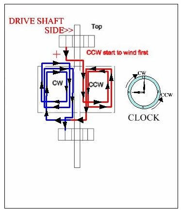
    The only thing you changed in your drawings was the arrow showing rotation and the position of the connections to the commutators being reversed this means that the current to the coils is reversed
    You call the commutator connections Front and Back UFO calls them Top and Bottom

    Please examine this diagram closely


    This is the convention UFO has stated he uses in all his drawings
    here you see the positive wire coming from the top
    The part winding that is CCW is producing a SP and the part winding being CW producing a NP
    Now on your armature where the brushes connect apply a small voltage say 3v with the positive to the top and the negative to the bottom (only use a low voltage as the coil would heat up)
    Now take a magnet and check the polarity of the armature windings
    Next reverse the current and now using a magnet check the polarity of the armature windings
    Notice that the poles are now reversed
    This change in polarity is not shown in your drawings

    this is what you have done in the two drawings in your post you did show the direction the arrow changing BUT YOU DID NOT show the change in the polarity of the Armature by changing the connection from front to back you are really changing the direction of the current from top to bottom and this is what makes the Motor turn in the opposite direction.

    I hope this makes things clearer
    Kindest regards my friend

    Kogs trying to be helpful

    Leave a comment:


  • Ufopolitics
    replied
    Mag3??!!

    Originally posted by Cornboy 555 View Post
    Hello Menace22, are you wanting custom design laminations?, or standard small motor laminations?.

    Regards Cornboy.
    Hey Cowboy...sorry, Cornboy..

    Where The HECK is our MAG3??!!

    Kogs is in Australia...He started his Imperial WAY after you started this work...and by now Kog's Imperial Machine is riding all over the land of down-under!!

    Regards, and just kidding...I know you are busy friend.


    Ufopolitics
    Last edited by Ufopolitics; 03-04-2014, 12:06 AM.

    Leave a comment:

Working...
X