Originally posted by sampojo
View Post
Honestly, I did not notice any difference in your "edited post" diagrams...

Otherwise I continue on the pains of not having a clean commutator to work with as I have devised a hopefully robust solderless connection method. I ask readers and Ufo to comment on whether the mounted connector in the picture below looks strong enough.
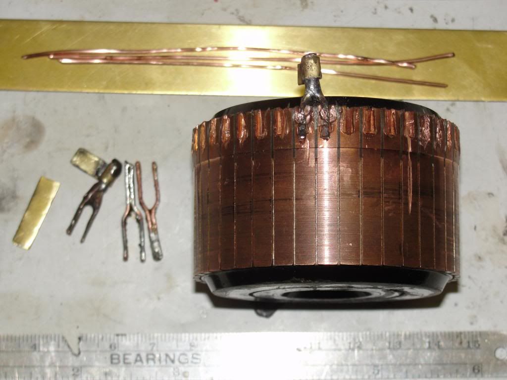
I am making a doubled 19ga tuning fork style connector mount that joins my 2 comm segments into 1, as it is 40-segment commutator for a 20 pole motor, designed to meet standard asymmetric requirements. I use a little solder on cleaned magnet wire to hold it together for shaping. It then acts like a flux for the brazing metal I use. Wrapping my brass connector is the last step, and no heat needs to be applied to the commutator.
I have installed one connector. It seems to pass strength needs as it is very solid feeling, and when I stamped it in, I seem to have gotten enough of the copper commutator to seal over the wire, even though it did not look possible when I started. I stamped the beads sticking out at the end of the fork on the other commutator where I had to install one wire, but dont want to here as it will loosen the primary stamp again and I don't know how many of those I have in a given installation. The beads will keep it from pulling out also. If they loosen I would restamp again, and would be an easy thing to inspect on a built motor.
So how's the stamp look to you, UFO?
TIA
And finally:

My advice, start from post 1, advancing based on your comprehension. Build a small motor, and do the same for the "my-motors-got-me" thread.
Good luck!

I am making a doubled 19ga tuning fork style connector mount that joins my 2 comm segments into 1, as it is 40-segment commutator for a 20 pole motor, designed to meet standard asymmetric requirements. I use a little solder on cleaned magnet wire to hold it together for shaping. It then acts like a flux for the brazing metal I use. Wrapping my brass connector is the last step, and no heat needs to be applied to the commutator.
I have installed one connector. It seems to pass strength needs as it is very solid feeling, and when I stamped it in, I seem to have gotten enough of the copper commutator to seal over the wire, even though it did not look possible when I started. I stamped the beads sticking out at the end of the fork on the other commutator where I had to install one wire, but dont want to here as it will loosen the primary stamp again and I don't know how many of those I have in a given installation. The beads will keep it from pulling out also. If they loosen I would restamp again, and would be an easy thing to inspect on a built motor.
So how's the stamp look to you, UFO?
TIA
And finally:

My advice, start from post 1, advancing based on your comprehension. Build a small motor, and do the same for the "my-motors-got-me" thread.
Good luck!
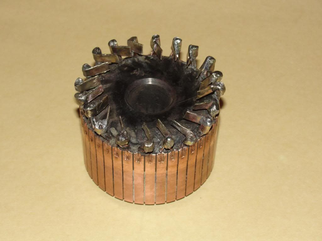
It looks good Sam...and strong...However, the only thing I do not understand is... why are you taking the tabs/plates to attach/clamp to your coils ends towards the Inner side of commutator and not outwards where there is so much space?
I really do not see the point...running all wires towards the interior, closer to shaft...gives you all kind of possible problems, besides being very uncomfortable to attach, clamp wires to brass plate in that zone, there is no way to check connections with a meter for future diagnosis...plus being closer to a naked shaft...could make short circuits or sparks to ground.
Maybe you have it all figured out...and coming up with a heck of idea...so...surprise me/Us...

Take care Sam...maybe the super cold weather have you "learning in disagreement"...

So Warm Regards friend
Ufopolitics

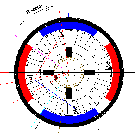
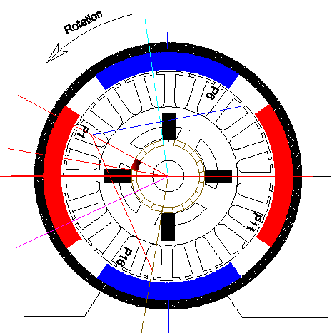



 just reverse the North-South (Colors change red to blue) whenever you reverse the voltage input...then follow reactions between P1 rotor and Red South stator and it will give you the rotation sense.

Leave a comment: