Announcement

Collapse
No announcement yet.

My Asymmetric Electrodynamic Machines

Collapse
X
 
  • Filter
  • Time
  • Show
Clear All
new posts

  • Ufopolitics
    replied
    Originally posted by HuntingRoss View Post
    Sometimes I write 'assume' or 'presume' to sound less emphatic, but really on this subject I have no doubt.

    [img][/img]

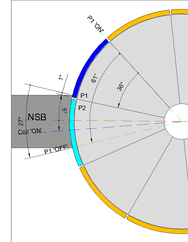
    To demonstrate the point of disagreement between us on the issue of timing, I present the 10 pole 4 stator commutator / brush angles for everyones consideration.
    Ok, Great!, it is Sam-po-Joe's Special Beauty!...

    The method I prefer is to consider the 'time on brush' for one comm segment from 1° 'ON' to 0° 'OFF'.
    Sounds good so far...

    For a single coil as we have been discussing in the recent past I would estimate it as so :

    A = 'ON' angle
    B = The angle of the comm segment
    C = The angle of the brush
    D = 'OFF' angle
    E = The angle between P1 and P2 coil bisectors
    The NSB and SSB stator bisectors are 90°
    Up to here I understand all codes written above...I guess you wrote P1-P2 as a Typo...since we are on Single Coils (underlined).

    Plus, it would help if you assign a Letter to Stators Bisector Angle.

    Where B + C = 'Time on brush'
    Ok, Mark, here we are both in agreement as to ADD comm. Segment Angle to Brush Angle...or a "Sweep Angle" (sA) from previous post right?

    Such that the 'OFF' angle of your proposed design (which must be a positive number variable around 20°) is -

    90 - A - B - C = D

    Crudely stating the comm segment as 36° and the brush as 27° and given an 'ON' angle of 8°, then

    90 - 8 - 36 - 27 = 19°

    More accurately from the image

    90 - 8 - 61 = 21° (B + C = 61°)

    To estimate the 'OFF' angle by reference to P1 and P2 together for single coils :

    90 - A - C - E = D

    Once again, to crudely estimate

    90 - 8 - 27 - 36 = 19°

    And with more accuracy

    90 - 8 - 25* - 36 = 21° (* The brush angle is reduced to account for the comm segment gap of 1° plus 1° connection)

    ---S---
    Yes Mark...of course You have it right this time...since you are Not Adding BUT Subtracting the Switch ON Time on ALL your above equations.


    Whilst you have not enlightened anyone on how to estimate the 'OFF' angle when designing your motor...
    Of course I couldn't "enlighten" anyone, just because you did not allow me to...with all your continuous arguments INSISTING ON keep ADDING the switch Angle to the Interaction Angles!

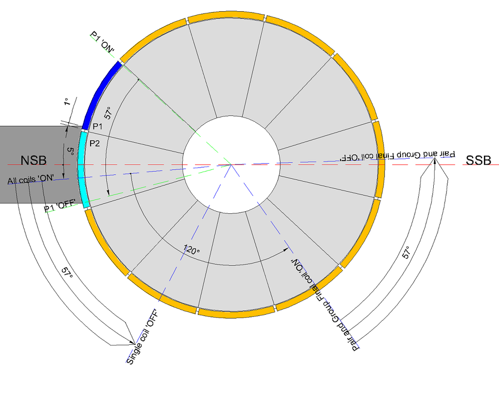
    you have demonstrated the result of considering it at the design stage, below.

    [IMG][/IMG]

    [IMG][/IMG]

    To calculate the advancement of the 'magnetic interaction angle' (coloured blue) toward the SSB, then

    90° (Stator bisector) - 8° (ON angle) - 21° (OFF angle) - 36° (coil bisectors or MIA) = 25° (being the angle of the brush reduced by the comm segment of 1° plus 1° connection)

    ---S---

    It's difficult to see the difference between one method and the other on account of there being NO difference...BUT...the difference is sufficiently large not to admit that there is ANY agreement at all.

    ---S---
    Mark,

    Of course We don't have any difference NOW!!...since you have rectified your mistake...and started SUBTRACTING instead of ADDING the ON Switching Time.

    Still, You have "divided" your Equations in Two Parts...and I don't understand why?...what is the point on doing so?

    First You subtracted ONLY Switching Angles, meaning A,B,C & D to Stators Bisectors Angle (90º)...

    Then you mixed...

    90 - A - C - E = D

    or...

    90 - 8 - 27 - 36 = 19°

    Where E is the MIA, C is Brush Angle...and A is the ON Angle or Repulse Angle.

    Now, there is one "special" issue (I will better call it "Unique") in Sampojo's 10 Pole/4 Stators and 4 Pole Single Coils:

    In that motor the Magnetic Interaction Angle (MIA) is exactly identical to the Commutator Segment Angle...Both being 36º...which is a very rare "Relation" to find in any other Four Stator Motor.

    Meaning E=B


    It tends to certain confusion when we add or subtract the number "36º" in any of above equations, no matter what letter is assigned...since the results would be the same. So in both equations is understood the results are the same.

    NOW LET'S VERIFY IF YOUR EQUATIONS ABOVE HOLD TRUE IN A CONVENTIONAL MOTOR:

    So let's choose Imperial, since it is a Four Stator as well, except E is not equal to B

    [IMG][/IMG]

    So We have Pairs P1 and P2 each engaging Four Poles:

    A = 'ON' angle=
    B = The angle of the comm segment = Here we use Two Segments, cause they are 56 total, each Two is then @ 12.85º round to 13º
    C = The angle of the brush= 13º
    D = 'OFF' angle = ?
    E = The angle between P1 and P2 coil bisectors = 64.85º = Let´s round it to 65º
    F=The NSB and SSB stator bisectors are 90°

    Let's "clean" all this below:

    A=5º
    B=13º
    C=13º
    D= ?
    E= 65º
    F= 90º

    So let's calculate D , and we all know D= 90-5-65 which is exactly 20º...

    According to Mark's Equation:

    D= 90 - A - C - E

    D= 90- 5 - 13 - 65

    D= 7

    So, unfortunately finding D don't work on your above Equation Mark.

    Now let's use your other Formula...:

    90 - A - B - C = D

    D= 90-5-13-13

    D= 59


    Close, but Nope...it can not be applied to a "Conventional" Motor Mark...so we can not use it as a "Universal Applicable Equation" am really sorry...just because We will have to keep "Hunting"...


    Hopefully that clears up any confusion on why we don't agree.


    Happy Hunting

    mark

    Even though the negative results trying to calculate Imperial...I am still happy you are not adding switching angles...but deducting them...which I consider a step forward in our Timing Calculating Process.


    Keep Hunting (hopefully very happy...)


    Ufopolitics
    Last edited by Ufopolitics; 05-28-2015, 05:34 PM.

    Leave a comment:


  • Ufopolitics
    replied
    First: Reviewing Previous Discussion

    @Mark Ross,

    Ok, Mark...I also want to reach an agreement here, believe me...for the sake of all members attending this Thread, and, of course, mainly to the ones actively replicating this Machines.

    As...in the end everyone will get benefit out of our final conclusion.

    What am doing on this Post is reviewing our initial arguments related to Timing...and I will be just showing the essential parts of concern, since there is a LOT of text involved from both of Us.


    Originally posted by HuntingRoss View Post
    Excellent graphics as always UFO which paint the picture perfectly...AND...we agree, it seems.

    [IMG][/IMG]

    I didn't want to go into fractions of degrees when broad principles establishes the point, but I can.

    I referred to 'pole angles' as 'A' being 1/28 of 360°...which is 12.857°
    The angle between P1C2 and P2C1, I referred to this as 'Z' being '5A' ...which is 64.285°
    I notice you have indicated the brush width as being approximately 50% of the comm segment width, not full width as it is in my 12 pole motor. This reduces the sweep angle 'sA' before P2 disconnects from 12.857° to...6.428°
    Ok, Mark up to here you were doing the Wrong Calculations for the Brush Sweep Angle (sA) ...look above and then below:

    When comparing your previous above calculations to our latest conclusions, starting at My "Five Frames Film Strip Diagram"...We both agreed that the Total Sweep Angle or ON Angle is equal to: Commutator Segment Angle PLUS Brush Angle.

    You obviously were deducting instead of adding both angles...

    But, the CENTER and MAIN Discussion STARTS below:

    Originally posted by HuntingRoss View Post
    ...So

    X + Z + sA + Y = 7A = 90°

    Substituting

    X + 64.285° + 6.428° + Y = 90°
    X + Y = 19.287°

    X is tunable in the region of 5° from previous posts AND
    Y wants to be in the region of 20°

    Which adds to more than 19.287°

    Of course for the 12 pole 2 stator motor X and Y can not squeeze up to accommodate -

    'Z' being '5A' being 5/12 of 360° ...which is 150°
    The brush width being the comm width 'sA'...which is 30°

    So

    X + Z + sA + Y = 180°

    Substituting

    X + 150° + 30° + Y = 180°
    X + Y = 0°

    And therefore is not achievable.
    Ok, On your above Formulas You were ADDING sA (even the wrong total ON Angle Calculation...but the point is here you were ADDING Sweep Angle to Magnetic Interaction Angle (MIA)...


    Originally posted by Ufopolitics View Post
    Mark,

    [...]

    I am glad We agree up to a certain point, which is 360/28=12.857...as well as Five (5) Total Poles from start repulse bisector PIC2 to P2C1 create a 64.85º Angle. But let´s be even simpler here, so let´s round up 64.85 to exactly 65º

    That is all I need friend...no more angles within rotor nor commutator...but NOW, let's go from North Stator Bisector to South Stator Bisector...and we have exactly 90º.

    Now let's 'fit' 65.0º of Rotor Interaction Angle within 90º of Stators...from N1 to S1 Stator (which is only Half of Total Rotor Interaction, remember this is a Four(4) Stator)

    We set P2C1 Bisector away by 5º (towards rotation) related to North Stator Bisector , meaning we are now at 70º...and now...just the simplest math on this world...

    How much is 90º-70º=?

    Yes, exactly that... 20º, that's how far we are from South Stator Bisector.

    We have 20º to play from either side of both stator's bisectors (which is 90º)
    Up to above point I am agreeing with You...great, BUT then I tried to rectify your error about adding Switch Angle to MIA:

    Originally posted by Ufopolitics View Post
    You can NOT add EVEN 1º MORE TO 64.85º or even rounding to 65º, that is the Rotor MAX Interaction Angle based on Two Pairs being fired at same timing, when it is just one Pair being fired this Angle REDUCES TO Approx. 52º (4 Poles from Bisector to Bisector on One Pair =12.85º X 4= 52º)

    I really have absolutely NO IDEA WHY...You have to "KEEP ADDING" Commutators and Brushes angles to 65º from MAX EXTERIOR INTERACTION ANGLES, IF all those Commutator/Brushes Angles are COMPLETELY RELATIVE, as COMPLETELY IRRELEVANT TO MAGNETIC INTERACTIONS!!??


    The wires from Pair Coils to be attached to Commutator Elements-Brushes...I could flex, pull, stretch, Turn them left or right...up or down and connect them wherever I please to do...within interacting angles, or away by 10, 20, 50 100 degrees...it DOES NOT MATTER...that is just an ON-OFF Switching...as a matter of fact one could be in Japan, while the other one in Ireland...don´t care....or be Remote Control by all means...it does NOT ADD NOR SUBTRACT to the REAL MAGNETIC INTERACTIONS taking place.

    So, above was shown the "essence" of our main arguments...which is to ADD Switch Angle, or Comm. Segment PLUS Brush Angle to Magnetic Interaction Angle...

    Are we agreeing so far?

    Ok, let's end here "the Past" and go into "the Present"...your Latest Post next


    To be Continued...


    Ufopolitics
    Last edited by Ufopolitics; 05-28-2015, 02:10 PM.

    Leave a comment:


  • sampojo
    replied
    Question on this calculation

    Originally posted by HuntingRoss View Post

    To extend my 'flawed' method of estimation (notwithstanding the same outcome, just luck I suppose) to the 12 pole 4 pole pairs wind -

    A = 'ON' angle
    B = The angle of the comm segment
    C = The angle of the brush
    D = 'OFF' angle
    F = The angle between P1 Coil 1 and P1 Coil 2 bisectors
    The NSB and SSB stator bisectors are 180°

    180 - A - B - C - F = D

    Crudely

    180 - 5 - 30 - 30 - 120 = -5°

    More accurately

    180 - 5 - 57 - 120 = -2°

    The negative number denotes the coils remained energised past the SSB when they should disengage prior to the SSB.

    Hopefully that clears up any confusion on why we don't agree.


    Happy Hunting

    mark
    So Mark, I don't think I see the above calculation highlighted in purple applying to the dual coil group for the 12 pole, done for the 10 pole. I know it only has the single coil. But I guess this type of calculation can prove that a coil will not be improperly energized past the top dead center of any magnet sector bisector. I think I can make the substitutions to get that calculation, but just thought I'd ask for now... I guess the 4-pole coil doesn't have this problem you show for the 12-pole?

    Sam

    Leave a comment:


  • HuntingRoss
    replied
    Originally posted by Ufopolitics View Post
    Have anyone here- including You- done ANYONE of those two simple tests?
    Firstly. It never even occurred to me that I should. For the motor speeds that I've been encountering and the fact they do not 'sit' locked onto the RPM, I have never thought that was even measurable. Trying some lower voltage tests might be sufficiently illuminating for me to try. And thank you for suggesting it.

    Secondly. I shall re read your post to fully digest the information.

    My thoughts on these motors and how they behave between connection has changed in the last few days. Your Imperial diagram, when it is motoring on all 4 gates must be firing north on the north magnet and south on the south magnet to rotate by repulsion. I'm going to pay my mind to this and what implications it has for my current interest in the single comm hybrid design.

    Delightedly Hunting

    mark

    Leave a comment:


  • HuntingRoss
    replied
    Originally posted by Ufopolitics View Post
    Even at those 25º resulting in 21º left at South Stator Bisector...you kept refusing about a 2º difference, where-according to your wrong assumption/presumption- it was NOT 21º BUT 19º.
    Sometimes I write 'assume' or 'presume' to sound less emphatic, but really on this subject I have no doubt.

    [img][/img]

    To demonstrate the point of disagreement between us on the issue of timing, I present the 10 pole 4 stator commutator / brush angles for everyones consideration.

    The method I prefer is to consider the 'time on brush' for one comm segment from 1° 'ON' to 0° 'OFF'.

    For a single coil as we have been discussing in the recent past I would estimate it as so :

    A = 'ON' angle
    B = The angle of the comm segment
    C = The angle of the brush
    D = 'OFF' angle
    E = The angle between P1 and P2 coil bisectors
    The NSB and SSB stator bisectors are 90°

    Where B + C = 'Time on brush'

    Such that the 'OFF' angle of your proposed design (which must be a positive number variable around 20°) is -

    90 - A - B - C = D

    Crudely stating the comm segment as 36° and the brush as 27° and given an 'ON' angle of 8°, then

    90 - 8 - 36 - 27 = 19°

    More accurately from the image

    90 - 8 - 61 = 21° (B + C = 61°)


    To estimate the 'OFF' angle by reference to P1 and P2 together for single coils :

    90 - A - C - E = D

    Once again, to crudely estimate

    90 - 8 - 27 - 36 = 19°

    And with more accuracy

    90 - 8 - 25* - 36 = 21° (* The brush angle is reduced to account for the comm segment gap of 1° plus 1° connection)

    ---S---

    Whilst you have not enlightened anyone on how to estimate the 'OFF' angle when designing your motor, you have demonstrated the result of considering it at the design stage, below.

    [IMG][/IMG]

    [IMG][/IMG]
    [/QUOTE]

    To calculate the advancement of the 'magnetic interaction angle' (coloured blue) toward the SSB, then

    90° (Stator bisector) - 8° (ON angle) - 21° (OFF angle) - 36° (coil bisectors or MIA) = 25° (being the angle of the brush reduced by the comm segment of 1° plus 1° connection)

    ---S---

    It's difficult to see the difference between one method and the other on account of there being NO difference...BUT...the difference is sufficiently large not to admit that there is ANY agreement at all.

    ---S---

    [IMG][/IMG]

    To extend my 'flawed' method of estimation (notwithstanding the same outcome, just luck I suppose) to the 12 pole 4 pole pairs wind -

    A = 'ON' angle
    B = The angle of the comm segment
    C = The angle of the brush
    D = 'OFF' angle
    F = The angle between P1 Coil 1 and P1 Coil 2 bisectors
    The NSB and SSB stator bisectors are 180°

    180 - A - B - C - F = D

    Crudely

    180 - 5 - 30 - 30 - 120 = -5°

    More accurately

    180 - 5 - 57 - 120 = -2°

    The negative number denotes the coils remained energised past the SSB when they should disengage prior to the SSB.

    Hopefully that clears up any confusion on why we don't agree.


    Happy Hunting

    mark

    Leave a comment:


  • bistander
    replied
    Originally posted by Ufopolitics View Post
    I want to Thank You Bistander, for making me stay to answer your post...This make me reach the 1million Views...
    Congratulations. A million views of your misinformation and double talk. You must be very proud.

    Leave a comment:


  • Ufopolitics
    replied
    POST marking the 1,000,000 Views!!!

    Originally posted by bistander View Post
    Ufo,

    So when you gave me that "I am wrong" answer in post #7750 you weren't serious and you really do believe ceramic permanent magnets are stronger than electromagnets? Sad.

    I'll just go back and stand on the sidelines.

    bi

    Bistander,

    It was NOT just a "simple" answer to please either you or me.

    There is a WORLD of difference between an Electromagnet and a Permanent Magnet.

    It ranges from their Field Spectrum Geometry, to each one's different "originating" sources...to the extent about what one is produced from and what the other has become...

    It was and still IS a very clever answer...that just does not obey to who is right or who is wrong.

    I decided to assume the wrong position.

    But I will just ask you a question about this same issue.

    Why do you think, according to your learned experience, that an electromagnet surrounding a ceramic piece of non magnetized ferro-material...and once you run a current...vualá...it is magnetized "For Ever"...while the electromagnet once the current flow ceases...it becomes just a piece of common iron core tubing and some dead copper?

    It is a very simple operation that everyone knows about...magnetizing a piece of iron...or ceramic.

    But no one could be able to really explain why...that now, ceramic magnet has become permanently magnetized?

    Yes, I do know the "typical" answer... :

    The "Magnetic Domains" inside that ferromagnetic material has been "oriented" according to the current flow...right?

    Yes, so, how do we "read" that?...Oh!, absolutely...we grab some iron loose particles over a piece of white paper...lay it over our newly magnetized ceramic, and BOOM, there "they" are...the "IMAGINARY Lines of Force"...that dictates the way domains has been aligned...

    end of research.

    Over.

    Now...do you really believe that is the final, and true answer about what happened to that magnetized piece of ceramic?

    You have here exactly two "pills" to take...Blue or Red.

    If you are satisfied with that typical and too simple and cheap answer...then fine...keep going on...and I will retract all I have written above and say again...

    "Bistander, I am wrong"


    Take care


    Ufopolitics


    EDIT: I want to Thank You Bistander, for making me stay to answer your post...This make me reach the 1million Views...
    Last edited by Ufopolitics; 05-27-2015, 05:11 PM.

    Leave a comment:


  • bistander
    replied
    You don't say what you mean?

    Originally posted by Ufopolitics View Post
    If I have written "I am wrong"...it was because the way I have answered before...when I AM SURE I WAS NOT...Got it?
    Ufo,

    So when you gave me that "I am wrong" answer in post #7750 you weren't serious and you really do believe ceramic permanent magnets are stronger than electromagnets? Sad.

    And I have spent considerable time reviewing this thread and others on this site. I find all the quarreling and fussing over minute details quite boring. I was primarily searching for a test under load showing efficiency. There were a few but all contained flaws in the data collection method.

    I'll just go back and stand on the sidelines.

    bi

    Leave a comment:


  • Ufopolitics
    replied
    Originally posted by HuntingRoss View Post
    I believe you have written in the past, that a north (or south) projecting field will collapse as a north (or south) projecting field.
    Originally posted by Ufopolitics View Post
    Never, ever written such non sense thing.

    Read my very first thread here...it don't matter the CW nor CCW for a Collapsed Coil to reverse voltage polarity.
    Mark, your quoted statement above is not specific, as to what kind of coil and where it is installed or affected by which specification is referring to.

    You never mentioned when such Coil is INSTALLED in an ALL NORTH Motor, SHARING SAME EXACT IRON CORE from other energized coils.

    I believed you were referring to Coils in general, an ISOLATED COIL, not affected by SEVERAL surrounding overlapped coils, also projecting OTHER Magnetic Fields, which DO INFLUENCE its behavior.

    That is why I cited my first Thread in my answer, which is completely based on STATIC and ISOLATED COILS.

    So, you are first asking me...

    Originally posted by HuntingRoss View Post
    So you didn't write this -
    Then, citing my SPECIFIC comment on the All North Machines, Coils behavior:

    Originally posted by Ufopolitics View Post
    [...]Now, we must realize this Coil Groups are ALWAYS NORTH...even when collapsing, they are collapsing North Coils...meaning Weaker Norths than the ones that are being energized...
    A completely different scenario than an Isolated Coil projecting a collapsing field.

    In the All North Machines, each independent COLLAPSING coil is INFLUENCED MAGNETICALLY BY other ACTIVELY ENERGIZED COILS in the whole sequence taking place, in TWO WAYS:

    1-By SPATIALLY PROPAGATED MAGNETIC FIELD INFLUENCE.

    AND

    2-By DIRECT COMMONLY SHARED IRON CORE, WHICH TRANSFERS ITS INFLUENCE VIA FERROMAGNETIC MASS.

    That is why I wrote above statement, that You have taken your time to search for and brought here as a "proof"...attempting to make me look I was either "forgetting", "lying" or completely "confused" about.

    I am VERY FIRM about everything I have written here, although, we are not perfect, we keep searching into the "unknown" every second of our research for Free Energy.

    However, on a SINGLE, STATIC and INDEPENDENT COLLAPSING COIL AND IRON CORE, NOT INFLUENCED BY OTHER FIELDS, it is a completely NONSENSE, to write it will collapse in a DEFINITE AND EXACT MAGNETIC POLARITY.

    I have conducted several Tests trying to establish IF or NOT a Static Coil is swapping its Magnetic Polarity as well...it is ALL on my first Thread, as well as ALL Videos on each related Testing.

    First and related to Asymmetric Motors...None of Us -that I know off- has installed a magnetic sensor, connected to a read out circuit within the specific point inside the Stator area...to find out which polarity is CONSTANT after collapse. It will be great to find out!

    Second, in Static Coils, this swapping magnetic polarity at collapse has brought several discussions/arguments all along since my First Thread here, and back a long time ago...and I am not going to "Re-Open" that case at this stage of time.

    The only REAL thing that we are SURE OFF, it takes place in both cases...is that they DO REVERSE VOLTAGE POLARITY, since it is easily measured a clear read out with any cheap DMM.

    On the Asymmetric All North Machines, it could be checked, once we have a full control and understanding over timing settings:

    1-IF, when we set Timing to PASS South Stator Bisector...and We notice a SLOW DOWN in the RPM's of Rotor...then we know that the specific COLLAPSING COIL at Stator Bisector is NORTH.

    OR...

    2-IF, when we set Timing to PASS South Stator Bisector...We notice a SPEED UP/ACCELERATION in the RPM's of Rotor...then we know that the specific COLLAPSING COIL at Stator Bisector has collapsed into SOUTH polarity.

    Based on THOSE TWO SIMPLE TESTS, we could notice which way the coil is collapsing.

    Have anyone here- including You- done ANYONE of those two simple tests?

    If You would've, then you would have the answer, and no need to ask me which way it happens.

    It is a VERY COMFORTABLE POSITION, to just WAIT for that "someone" who will do it Uh?...But in the meantime we just keep trying to proof others are wrong, or full of it...or keep "assuming and presuming"..."tinkering"...and theorizing, while having a cup of coffe in front of our PC's...that is a great "by standing" position...but a very poor Open Source behavior, as a terrible Scientific research method.

    Originally posted by HuntingRoss View Post
    OR...did I just misunderstand it ?

    I maybe do.
    If you would have read well my written post -that you brought over here- related to collapsing all north coils...you should have realized I wrote also that those collapsing coils tend to keep their North orientation, HOWEVER, they were "WEAKER NORTHS" or "Less North" than the active ones. That could also be interpreted as "if they are "less North" ...well, then that could mean they are tending to be "More South" related to the active North ones.

    One interesting issue I found in Asymmetric Machines, is that even in a simple, small five or three pole motor, the rear negative at generator...is not actually a "full Negative"...nor a "Full Positive" when comparing it to either one of the main Input Polarities. It could play like a "Neutral" point in between both top voltage polarities...and we could read out a steady voltage, from both connections using that specific Negative terminal.

    I know that voltage and field are not the same thing...but I did think reversing one meant reversing the other. It appears that I may be mistaken...and not afraid to admit it if this is the case.
    You will encounter a lot of opposition to your statement above (basically the underlined part)...not coming from me...but, from the "Educated" Community of the Established Electric Engineering Schools.

    So far, the NATURAL Voltage Reversal of a given COLLAPSING coil, has MAINLY been applied to the "INDUCTOR" application in the Electronic Engineering development...where that "Inductor" has been "statically" soldered in an isolated circuit board, away from any magnetic interaction, like we are doing with Asymmetric Machines... so, there is no way of knowing...if or not magnetic polarity is also switching...as Engineers don't give a "who" if or don't.

    All they care, is that whenever Inductor reverses polarity a "Filtering Diode" will allow that reversed flow be sent to output caps, when switching a Square wave to Coil. (Search for BUCK or BOOSTER as SEPIC Converters)

    I understand that. The context here is 'one commutator' meaning symmetrical motor.

    My question was in the 'single comm hybrid' you do have down time and therefore a south coil collapses in the down time just as you say it does in your four stator diagram. The four stator does it in a quarter turn...therefore the single comm hybrid does it in half a turn. If it works for one it must work for all.

    Hence the logic and more of the dripping sarcasm...

    Happy (as ever) Hunting

    mark
    You have to look at overall interactions taking place there (at hybrid)...even being multiple ones, and not just focusing/following a single coil 'possible' behavior. Also You must look at what kind of Magnetic development is taking place at that ferromagnetic CORE, here known as the Motor Armature...then compare it to the way it evolves/develops in an All North Machine.

    Like I mentioned above, the Magnetic INFLUENCE is something we have been ignoring for a long time...by constraining to "Lines of Force" within a given Field...

    Single Commutator Hybrids...no matter if they do go into an OFF stage...the ferromagnetic core is FRAGMENTED and that fact, constantly affects North South Influences within its mass to the Interacting Coils.

    Keep being "happy" it is a great "State of Mind"...


    Ufopolitics
    Last edited by Ufopolitics; 05-27-2015, 01:17 PM.

    Leave a comment:


  • Ufopolitics
    replied
    Originally posted by HuntingRoss View Post

    BUT importantly, you do not respond to the single most important point.

    You agreed...with me...that the rotor advanced 25° off the brush to give the 'off' angle.
    Mark,

    Even at those 25º resulting in 21º left at South Stator Bisector...you kept refusing about a 2º difference, where-according to your wrong assumption/presumption- it was NOT 21º BUT 19º.

    Which is what I said all along and you refuted.

    Still Hunting

    mark
    ALL along this discussion you have been adding Brush Angles PLUS Interaction Angles, like if they will take place at different TIMES and Spaces, overlooking the FACT they are SIMULTANEOUS TIMED ANGLES that spin within same Rotor.

    Until You accept that Both Angles can NOT be added SEPARATELY We can not agree on this Timing Issue.

    And I will keep refuting about adding both angles, just like 2+2=4

    IF whenever you rotate the shaft, you notice Brush Angle spins AS WELL AS Interaction Angle, how can you add them separately like occurring at Isolated Times and Space?

    This -I thought- is something very simple to digest/understand and get to an agreement easily...but obviously for you it is Not.


    Ufopolitics
    Last edited by Ufopolitics; 05-27-2015, 01:58 PM.

    Leave a comment:


  • HuntingRoss
    replied
    Originally posted by Ufopolitics View Post
    Never, ever written such non sense thing.
    So you didn't write this -

    Originally posted by Ufopolitics View Post
    Now, we must realize this Coil Groups are ALWAYS NORTH...even when collapsing, they are collapsing North Coils...meaning Weaker Norths than the ones that are being energized...
    OR...did I just misunderstand it ?

    Originally posted by Ufopolitics View Post
    Again wrong...Mark you do have a serious problem understanding/reading me...
    I maybe do.

    Originally posted by Ufopolitics View Post
    Why you keep writing "reversing the field"?...or...is it the same thing for you?...voltage or field, the same deal?
    I know that voltage and field are not the same thing...but I did think reversing one meant reversing the other. It appears that I may be mistaken...and not afraid to admit it if this is the case.

    Originally posted by Ufopolitics View Post
    One Commutator, simply changes VOLTAGE POLARITY as soon as circuit passes the brush planes, there is no OFF/IDLE "thing" happening at all...VERY ACTIVELY ENERGIZED COILS, are Injected a REVERSED VOLTAGE FLOW completely AGAINST THEIR WILL...AND THAT, IS ONLY CALLED FORCED AND "FACE ON" ELECTRONIC COLLISION.
    I understand that. The context here is 'one commutator' meaning symmetrical motor.

    My question was in the 'single comm hybrid' you do have down time and therefore a south coil collapses in the down time just as you say it does in your four stator diagram. The four stator does it in a quarter turn...therefore the single comm hybrid does it in half a turn. If it works for one it must work for all.

    Hence the logic and more of the dripping sarcasm...

    Originally posted by Ufopolitics View Post
    Wow...what a "logic" explanation...

    for the first time on this post or should I say...ever?
    Happy (as ever) Hunting

    mark

    Leave a comment:


  • HuntingRoss
    replied
    Originally posted by Ufopolitics View Post
    Whoever sides with my declared enemy...
    It seems you're not without presumptions too.

    BUT importantly, you do not respond to the single most important point.

    You agreed...with me...that the rotor advanced 25° off the brush to give the 'off' angle. Which is what I said all along and you refuted.

    Still Hunting

    mark

    Leave a comment:


  • Ufopolitics
    replied
    Originally posted by HuntingRoss View Post
    Wow.

    What a tirade of insults and personal abuse.

    Not once have I insulted you or made any kind of personal comment despite your provocation.

    You don't even have the good grace to admit that we agreed on the 10 pole discussion (and therefore the entire timing debate) by your submission of the two schematics that showed the rotor advance by 25°...the 25° that represents the face width of the brush with 2° deducted for gap and connection.

    You call me a clown, but I'm the only one that brought you all the way through that discussion to admit I was correct by submission of diagrams...no words or explanation from you as to why.

    You quote Garry, but omit his immediate apology for not understanding that coil groups have bisectors that extend their field of influence towards the south stator which can have serious implications on performance as the motor advances over the brush.

    You will not drag me down with your comments.

    Still Hunting

    mark

    Whoever sides with my declared enemy...is my "automatic" enemy...long time law...

    If I review all your history here as a "rookie" it has never brought any good results...except for your very first test...where you said it was due because of your "rookie" Unacknowledged state...or inexperience with motors...

    And now you are "helping" this ******* to keep his Hijacked Thread alive...by criticizing there and NOT HERE...all my work.

    Where You obviously know absolutely nada, you keep "presuming and assuming" ...but agree to keep agreeing...with the other clown.

    It is up to you to keep doing whatever you are doing so far, but don't try to play in Heaven and Hell...like nothing is happening...or like I am not reading the Big clown's thread.

    This is great that all this is taking place here and there...

    Leave a comment:


  • Ufopolitics
    replied
    Originally posted by GChilders View Post
    @UFOPolitics

    Hello Raul I have finished my Imperial modifications and am ready to wind the rotor. I have sent a very short video in a PM to you. I am deviating slightly on the winding and needed your input on a couple of fine points. This is a really fine motor. Wish they had not started gouging people with the new guy.
    If you have the time would appreciate a response.

    Cheers

    Garry


    Hello Garry,


    I responded your mail, it looks great!

    Sorry about all this noise here!

    Regards


    Ufopolitics

    Leave a comment:


  • Ufopolitics
    replied
    Originally posted by HuntingRoss View Post
    I believe you have written in the past, that a north (or south) projecting field will collapse as a north (or south) projecting field.
    Never, ever written such non sense thing.

    Read my very first thread here...it don't matter the CW nor CCW for a Collapsed Coil to reverse voltage polarity.

    If the above design is fired from all four gates. I presume that to do so the coils on the north magnets have to project north as drawn and therefore presume that the other coils would have to project south on the south magnets.
    You are again..."presuming=assuming"...the wrong way

    If I understand what you're saying here, the south fields collapse north (naturally) and therefore do not flik-flak when arriving at the north magnet brush.
    Again wrong...Mark you do have a serious problem understanding/reading me...I never wrote "reversing magnetic polarity" above...but reversing Voltage Polarity...very different thing.

    So if I'm understanding that correctly, then a north field does not collapse as a north field and I'm mistaken that you said that before.
    Definitively, and again, you do are mistaken.

    So if the above design naturally reverses the field, then why does the single comm design which you despise not do the same.
    I can not understand...why after you have previously posted my OWN WORDS above your post...and written in capital letters...where I write...

    AND...even if We feed from ALL FOUR GATES, for your lack of previous and basic knowledge, every time any type of COIL, INDUCTOR or BOBBIN is cut/stopped from supplying its feeding voltage, it NORMALLY REVERSES VOLTAGE POLARITY...SO, THERE IS ABSOLUTELY NO FORCED REVERSAL BY OUTER SOURCES, BUT "NATURALLY" DONE FROM ITS INTRINSIC REACTIONS.
    Why you keep writing "reversing the field"?...or...is it the same thing for you?...voltage or field, the same deal?


    IT IS NOT THE SAME AT ANY TIME...to allow Natural Flow Reversal FIRST, AND...after a period of OFF Time...THEN Inputting the energy...

    THAN FORCING it within an ACTIVELY ENERGIZED Circuit or system.

    One Commutator, simply changes VOLTAGE POLARITY as soon as circuit passes the brush planes, there is no OFF/IDLE "thing" happening at all...VERY ACTIVELY ENERGIZED COILS, are Injected a REVERSED VOLTAGE FLOW completely AGAINST THEIR WILL...AND THAT, IS ONLY CALLED FORCED AND "FACE ON" ELECTRONIC COLLISION.

    All that "Old Material" was originally uploaded on my First Two Videos on this Thread and Forum, in 3D and animated full color graphics...Oh! and FREE of charge!:

    SYMMETRY OF DARKNESS

    ASYMMETRY TO ENLIGHTENMENT

    I would presume the mechanics behind one electromagnet is the same for all electromagnets regardless of the number of comms and brushes.

    Curiously Hunting

    mark
    Wow...what a "logic" explanation...

    for the first time on this post or should I say...ever?

    Keep Hunting Ross...you are still far to find him..


    Ufopolitics
    Last edited by Ufopolitics; 05-26-2015, 10:00 PM.

    Leave a comment:

Working...
X