Announcement

Collapse
No announcement yet.

My Asymmetric Electrodynamic Machines

Collapse
X
 
  • Filter
  • Time
  • Show
Clear All
new posts

  • HuntingRoss
    replied
    Originally posted by GChilders View Post
    Do you not understand this principle?
    @ Gary

    I find it hilarious that people keep asking me THAT question.

    I am simply processing the information given. If people can not assimilate the information, then they should be asking the question of themselves. Not me.

    Keep Hunting

    mark

    Leave a comment:


  • Ufopolitics
    replied
    Sampojo Attract Mode...

    Ok, now this Post is addressed mainly to Sampojo 10 poles four stators...:

    @Sam,

    What am showing on below Diagram is basically setting your C1-C6 Coils which are apart by 180º...to fire further away from North Stators Bisectors. This way achieving a more "Attract Mode" than repulse.

    [IMG][/IMG]

    Above you are firing C1-C6 at 15º away from North Stator Bisector. And here, like demonstrated on prior post diagrams...you could fire them as close as 3º-5º, which case will deliver a higher percentage of repulse.

    Anyways...on below Diagram, am showing the Second Frame: Angle left over of 12º, when C2-C7 Disconnect-Die:

    [IMG][/IMG]

    So, as shown above..."leaving" Coils (C2-C7), according to rotation, "die" approximately at 12º before reaching both South Stators Bisectors.

    Whenever you build this type, you could play with all the "in-between" angles that would deliver lowest amp draw and still have good speed and torque.

    However, something important that you must realize here is that all depends upon operating speed and voltage delivery...since the fastest the rotor is spinning...the more "magnetic curvature deformation" of your rotor bisectors and whole rotating field will suffer...normally following rotation sense. Meaning, too short attract angles (no matter how beautifully they display such very low amperage) will tend to distort bypassing the South Stator Bisectors...then Motor will suffer a sudden slow down ...Which will normalize back as soon as you reduce feeding V.


    Regards friend.


    Ufopolitics
    Last edited by Ufopolitics; 05-20-2015, 03:51 PM.

    Leave a comment:


  • Ufopolitics
    replied
    Sampojo Ten Pole Critical Angles...

    Hello to All,

    I am going to focus this Post on Sampojo Ten (10) pole rotor, Ten (10) commutator segments and Four (4) Stators analysis.

    Based on above data, each commutator segment should be within the 36º.

    According to Sam his Brush is about 3/4 from his comm. segments which results in exactly a 27º width brush.

    The Stators Bisector to Bisector is a fixed 90º Angle.

    Based on Single Coils wound by four poles each and overlapped as I have proposed before, he had 36º from C1 Bisector to C2 Bisector...and the same between C6 and C7 apart at 180º.

    Seen on my original Diagram below:

    [IMG][/IMG]

    As you could notice, in above and below Diagrams I had the wrong brush width scale (they were done before Sam provided the right brush size), however, the angles of Interactions, the Coils grabbing Four Poles each...as Stators Angles plus rotations are all fine and Perfect.

    Then I laid off this second Diagram (see below), where I wrote the 21º away disconnect of C2-C7, from South Stator Bisector.

    [IMG][/IMG]

    And...here comes Mark and addresses the following Calculation to Sampojo (the little blue arrow will drive you to the original post link):

    Originally posted by HuntingRoss View Post
    Thank you Sam. As UFO has already remarked, that makes your brush approximately 27º wide.

    That means your connected comm has to sweep approximately 36 + 27 = 63º from connection to disconnection. Working with a combined 'ideal ON / OFF' angle of 25º, gives you 88º. Thats leaves 2º for timing adjustments.
    This means that Mark's calculations leaves him only 2º to play with timing...regardless of my previous post where I wrote in very legible text it was 21º when C2 was disconnected.

    There must be a very serious error Mark is doing when considering such small degree left (2º)to play with timing...and as he wrote...using an "ideal" 25º angle instead of 27º brush width. The only thing I could think off...is that Mark is considering the circumference of the commutator segments based on the same radius as the circumference-radius of Rotor to calculate that way...which case, no matter which motor we are referring to...such scale of 1:1 NEVER will take place.

    Below are just Two Sequence of Diagrams I have done related to this "scenario"...

    And for clarification...We only need two frames here...not three, not five.

    1-When C1 and C6 STARTS to make contact (ON STAGE)>>>>This defines the primary North to North Repulsion Angle.

    2-When C2 and C7 DISCONNECTS (OFF STAGE)>>>>This verifies that C2/C7 (LEAVE COILS) disconnect before reaching South Stator Bisector.


    And the "playing" gap between both Frames, will help us to find the Sweet Spot for Timing...so here we go (again):

    FRAME ONE (1) C1 and C6 STARTS to make Contact (ON STAGE)

    [IMG][/IMG]

    I have defined a Shaded Red Area as the Fixed Four Stators Interaction Angle, which is exactly 90º.
    I have set a Blue Shaded Area as the Four Coils involved in Interaction, which is exactly 36º.

    Seen this way that all we are doing here, is moving the Blue 36º Rotor Area WITHIN the Red 90º Stators Area

    I am starting to Fire C1-C6 Bisectors EXACTLY AT 8º Angle away from North Stators Bisectors. Which means C2-C7 Bisectors are located at 46º [8º+36º=44º-90º=46º] away from South Bisector (this residual angle not shown on Diagram)

    Now let's move on to next Frame...

    FRAME TWO (2) C2 and C7 DISCONNECTS (OFF STAGE)

    [IMG][/IMG]

    If You all notice above, C2-C7 are Disconnected, as I have passed Rotor/Comm. Segment from C2, beyond being "borderline Doubt" of 1º-2º but beyond...and ...I still get 21º left...and away from South Stator Bisector.

    As you all see, the best way to see this...is by shading Stators Area...as well as North Rotor Coils at Interaction Area...like shown above.


    Regards to All.


    Ufopolitics
    Last edited by Ufopolitics; 05-20-2015, 04:10 PM.

    Leave a comment:


  • Ufopolitics
    replied
    Originally posted by GChilders View Post
    @Mark
    After examining Post #7650 where UFO goes over the two new windings for the Imperial motor I am confused. He shows two coil bisectors for the two coils that are wound.
    Hello Garry,

    Yes, Garry that is correct, each coil projects a stronger concentration of its field exactly from their center.

    was under the impression that even though there are two coils being energized at one time that it still resulted in one magnetic field being produced and that the center of this magnetic field was in the center of both pairs.
    When We have Two Coils overlapped, in series, and wound in the same direction, each center of strength (bisectors) tend to 'blend' together, and it depends on how they are set Geometrically.

    1- The Overlapped 'Common' area they are sharing, where closer coils will project more compact bisectors.

    2- The Angle of Projection from each of their centers towards the outer circumference creates a divergence tending to separate them.

    When I experimented with dual coils on a naked rotor, and energized the coils the magnetic field produced by the coils had no dividing point. It was a north pole that influenced the swing of a compass needle. And that was over a much wider area than that of the coil. It influenced the rotor itself and magnetized it also. Perhaps I am mistaken in my understanding of the influence of the coils. If so I apologize.

    Cheers

    Garry
    You can not actually 'feel' this small separation between two stronger areas (bisectors) with just a compass needle movement. The needle tends to balance by seeking at a center between the two bisectors, since both are North polarization...And again, it depends on how close they are plus each angles of projection...so every set up is different according to rotor structure spec's.

    The best way to "see" this is by using two movable (loose) coils, with a fixed compass, then from a wider angle (not overlapped) start bringing coils closer into an overlap ..then you will notice how needle will go pointing between one and the other until it settles when bisectors are blended.


    Kind Regards


    Ufopolitics

    Leave a comment:


  • GChilders
    replied
    @Mark
    After examining Post #7650 where UFO goes over the two new windings for the Imperial motor I am confused. He shows two coil bisectors for the two coils that are wound. I was under the impression that even though there are two coils being energized at one time that it still resulted in one magnetic field being produced and that the center of this magnetic field was in the center of both pairs. When I experimented with dual coils on a naked rotor, and energized the coils the magnetic field produced by the coils had no dividing point. It was a north pole that influenced the swing of a compass needle. And that was over a much wider area than that of the coil. It influenced the rotor itself and magnetized it also. Perhaps I am mistaken in my understanding of the influence of the coils. If so I apologize.

    Cheers

    Garry

    Leave a comment:


  • GChilders
    replied
    Originally posted by HuntingRoss View Post
    It wasn't my intention to post further on this topic but I promised to wait a few days after my comments have been misrepresented.

    I will not dilute my point by picking apart UFO's interpretation of what I have said and drawn on this topic. Suffice to say that interpretation is wrong.

    I will reinforce what I have said firstly by thanking Jeffy for correctly stating my point and thereby assisting UFO in creating the 5 frame film strip. Which I agree with and this does represent what I have been saying.

    And secondly I have uploaded another graphic to further reinforce the following paragraphs.

    There are fixed parameters in our motors and there are variable parameters.

    Fixed being -
    1) Stator Bisectors
    2) Comm Segment Width
    3) Brush Width
    4) Number of Poles and therefore Pole angle
    5) Choice of Coil Structure (pairs or groups) establishes the Coil Bisector Angle. That is the angle between the first coil and final coil bisector

    Variable being -
    6) The 'sweep angle' or 'time on the brush' where the comm segment sweeps over the brush.

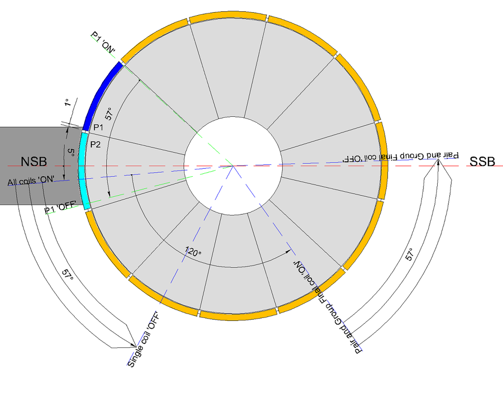
    For Single Coil and First Coil Pairs or Groups, we set the bisector at 5° past the North Stator Bisector (NSB) as the 'ON' time. This means that ALL coil structures attached to that connected comm segment are also 'ON'.

    For Pairs and Groups the Final Coil extends towards the South Stator Bisector (SSB) by an angle dependant on the chosen wind. For the image below I have used a Coil Bisector Angle of 120° which would represent a '4 Pole Pair' on a 12 Pole motor.

    The discussion on this particular aspect of winding, for me, was to estimate when P2 coils are 'OFF' so as to avoid the P2 'ON' coils bisector being within 20° of the SSB or possibly even past the SSB. This scenario will cause a drop in efficiency of the chosen wind.

    It becomes obvious when considering the mechanics of this, that one can consider the P2 'OFF' angle from when P1 just attaches to the brush, OR better still, just calculate it from the P1 'sweep angle' as it connects and disconnects from the brush.

    It is clear that the angle of ONE comm segment 'sweeping the brush' is the angle that the Final Coil Bisector advances towards the SSB from connection to disconnection. There is only ONE SWEEP ANGLE for a motor and it is a direct function of the OEM motor given by the width of the comm segment and the brush width in degrees.

    The image below, as before, indicates the comm segment is just 'ON' by 1° and 'sweeps' for 57° where it is 0° 'OFF'. It indicates where a Single Coil will be 'OFF' after 57° and it indicates where the Final Coil of a Pair or Group will be 'OFF' after 57°. For a 12 pole 4 pole Pair wind, we can see it passes the SSB and is unsatisfactory for 12 pole motors.

    [IMG][/IMG]

    Happy Hunting

    mark
    @Mark
    Mark I have tried to understand your argument and can see your confusion. The single coil bisector and multi coil bisector and group bisectors are a point and not an angle. By offsetting this point on the stator bisector a few degrees and having the coil energized at this point the rotor will rotate in the direction of the offset. It will rotate to the opposite pole stator bisector and when the center of the stator bisector lines up with the coil bisector the motor will stop rotating if not disconnected from the power prior to that point. Because the magnetic forces will have their strongest attraction at that point. The magnets will center themselves on each other. Do you not understand this principle? It is paramount in understanding the way the asymmetrical motors work.

    Cheers

    Garry

    Leave a comment:


  • HuntingRoss
    replied
    It wasn't my intention to post further on this topic but I promised to wait a few days after my comments have been misrepresented.

    I will not dilute my point by picking apart UFO's interpretation of what I have said and drawn on this topic. Suffice to say that interpretation is wrong.

    I will reinforce what I have said firstly by thanking Jeffy for correctly stating my point and thereby assisting UFO in creating the 5 frame film strip. Which I agree with and this does represent what I have been saying.

    And secondly I have uploaded another graphic to further reinforce the following paragraphs.

    There are fixed parameters in our motors and there are variable parameters.

    Fixed being -
    1) Stator Bisectors
    2) Comm Segment Width
    3) Brush Width
    4) Number of Poles and therefore Pole angle
    5) Choice of Coil Structure (pairs or groups) establishes the Coil Bisector Angle. That is the angle between the first coil and final coil bisector

    Variable being -
    6) The 'sweep angle' or 'time on the brush' where the comm segment sweeps over the brush.

    For Single Coil and First Coil Pairs or Groups, we set the bisector at 5° past the North Stator Bisector (NSB) as the 'ON' time. This means that ALL coil structures attached to that connected comm segment are also 'ON'.

    For Pairs and Groups the Final Coil extends towards the South Stator Bisector (SSB) by an angle dependant on the chosen wind. For the image below I have used a Coil Bisector Angle of 120° which would represent a '4 Pole Pair' on a 12 Pole motor.

    The discussion on this particular aspect of winding, for me, was to estimate when P2 coils are 'OFF' so as to avoid the P2 'ON' coils bisector being within 20° of the SSB or possibly even past the SSB. This scenario will cause a drop in efficiency of the chosen wind.

    It becomes obvious when considering the mechanics of this, that one can consider the P2 'OFF' angle from when P1 just attaches to the brush, OR better still, just calculate it from the P1 'sweep angle' as it connects and disconnects from the brush.

    It is clear that the angle of ONE comm segment 'sweeping the brush' is the angle that the Final Coil Bisector advances towards the SSB from connection to disconnection. There is only ONE SWEEP ANGLE for a motor and it is a direct function of the OEM motor given by the width of the comm segment and the brush width in degrees.

    The image below, as before, indicates the comm segment is just 'ON' by 1° and 'sweeps' for 57° where it is 0° 'OFF'. It indicates where a Single Coil will be 'OFF' after 57° and it indicates where the Final Coil of a Pair or Group will be 'OFF' after 57°. For a 12 pole 4 pole Pair wind, we can see it passes the SSB and is unsatisfactory for 12 pole motors.

    [IMG][/IMG]

    Happy Hunting

    mark

    Leave a comment:


  • Ufopolitics
    replied
    Originally posted by BroMikey View Post
    Hi UFO

    It is good to see you back working on your new motor. Thank you for all of
    your efforts getting you ideas out into the public domain. A small note
    on the trolls, these people want a free lunch, don't let them take yours

    It's show time for you and personally I am looking forward to better things.

    There are thousands of us and we all see how these trolls worm their
    way in twisting everything around. Take no prisoners, don't pet the trolls

    You are the best there is, thanks to all of the other guys too, I won't
    name them ALL, you know who you are, standing with UFO.

    We are with you UFO.

    Mikey

    Hey Mikey!!


    It is always good to see you come around!...You always bring a nice breeze of fresh air to some polluted and hijacked environment!


    Welcome anytime my friend!


    Ufopolitics

    Leave a comment:


  • Ufopolitics
    replied
    Originally posted by padova View Post
    greetings

    Citfa and company, what's yours game?
    You so blindly wrote all kind of rubbish about DC asymmetric motors,
    and yet here you are, in this forum. It seems that it is too late for you,
    considering your ages, to change your mind, nothing wrong whit that, just add to that some respect
    towards true researchers nothing more.
    With these conventional BS know you're not going anywhere.
    It's like you're stuck in the mud.
    I can only figure it out what a bunch of **strubating monkeys can learn something from you.

    I'm steel newbie here, but you people, in a few posts here are so offensive.
    Even worse than one who just copied someones work and started new thread.
    So funny.

    I couldn't care less, anyway I'm not into motors. so it's just small observation, and it's just a part of that, the rest you figure out by yourself.
    @Padova,

    Don't waste your time with this people!

    Did you see who responded?...Midaz the Hijacker...

    And now he has nothing else to do but to repost it on his boring promises thread...

    @Midaz: Go Hijacker do your piece of crap...with single coils...did you made up your mind between 5 or 6 yet?

    Leave a comment:


  • Ufopolitics
    replied
    Originally posted by grounded View Post
    figure 4 looks good to me, keeping the com segment wire short, so everythings close together, and compact.

    (unless you have to wind it a special way, to make everything line up)

    ive got fully adjustable brushes on mine, so luckily, A and C doesnt come into the equation for me
    Grounded,

    That is perfect!...make it "within" the magnetic Interaction Angle, you save connecting wire length...plus you do not need to participate on this silly argument...

    If it works fine for you then forget about everything else...


    Ufopolitics

    Leave a comment:


  • Ufopolitics
    replied
    Originally posted by esesenergy View Post
    any vids of any single coil motor working? anyone build anything that works as good as their mouths?
    Ask the Hijacker of My Thread (this Thread) if He finished all the bluff he has spread all over site...he is got such a big mouth...but his brain and hands are clumsy and limited...

    First he "discover" 6 poles single asymmetric coils was the solution...and now his small brain collapsed for just Five(5)...

    Like I am saying...it will take quite some time for his diminished processor to make up deciding between 5 or 6...too much data for its capacity to decide which way to go...and that is not counting with a possible overheating...

    I recommend to be patient while you wait...

    But I've got an idea......Why don't you buy it from him?...weren't you looking for an Imperial Motor before?
    Last edited by Ufopolitics; 05-18-2015, 09:45 PM.

    Leave a comment:


  • Ufopolitics
    replied
    Originally posted by jeffy39 View Post
    Howdy UFO, all,
    Hello Jeffy!


    RE: open to comments. Could the following explain your and HR's diff. views due to a conflict of terminology?
    Ok let see in detail...

    Assuming a 1" wide comm. element and 1" thick brush. Also assume the dia or circumference as such to require 10 deg rotation to cause 1" 'travel' on comm. surface.
    Your example is very simple, and it is great...the main shaft needs to rotate 10º to displace 1" width of commutator segment. right?

    It will take 10 deg rotation to bring brush's first contact to center the brush upon the comm. element. It takes 10 deg more to turn the switch off. Thus the 'coil' or pole is energized for 20 deg. of rotation.

    Please forgive if I'm all confused also.
    [IMG][/IMG]

    You are not confused at all, You are completely right Jeffy...Above I have done a "Film Strip" Diagram of each frame...from 1 degree contact to 1 degree left to disconnection.

    From leading top edge from Comm. Segment On to Off we have a complete 20º sweep...shown on End Frame 5.

    And...The total Time On for that Brush-Coil is also 20º.

    However, the Switch Sweeping Angle (let's call it SSA)...was not the Main "essence" of our argument...

    But IF the SSA requires or not to be added to the Magnetic Interaction Angle (MIA) from Energized Coils Bisectors, in order to reach a Total Sweep Angle to be "Inserted" within Stators N-S Bisector Angle...then Subtracting both, meaning with whatever "is left, if there is" to deal with timing.

    Mark express to Add them...I say We do not add them, since they take the same exact time to occur, so no matter where Switch is...they are both attached to the same shaft...and at different levels, where switch is away from magnetic interaction Level.

    Also, UFO, I've sent you an email re: another matter.
    Regards to all....jw
    Never got your email...was it on this Forum mail? or at my gmail address?...never got it on either one.


    Regards


    Ufoopolitics

    Leave a comment:


  • grounded
    replied
    figure 4 looks good to me, keeping the com segment wire short, so everythings close together, and compact.

    (unless you have to wind it a special way, to make everything line up)

    ive got fully adjustable brushes on mine, so luckily, A and C doesnt come into the equation for me

    Leave a comment:


  • Ufopolitics
    replied
    Misrepresentation Mark?

    Originally posted by HuntingRoss View Post
    Hi UFO

    I agreed to let other members respond and comment on this post, but I didn't agree to be misrepresented.

    Being true to my word, I shall wait a day or two (longer if you advise) before commenting.

    Happy Hunting

    mark
    Hello Mark,

    If You see any part of my related post that in any way I "misrepresent" what you were claiming, please, let me know and I will correct it.


    Your "side" to look at it was and is pretty simple...Adding All Angles in Interaction. meaning: A+B+C=Total Angle to be Fitted within North-South Stators Bisector to Bisector Angle...that simple. Given "Angle C" as the "Trailing Angle".

    My "side" was even simpler: You do NOT add Switching Angle(s) to Magnetic Interaction Angle(s), no matter where "the switch" is being positioned...it must be considered WITHIN the Magnetic Interaction Angle.

    Further more I proposed another Graphic (to see if you would react, and change your mind about your adding side) where I am clearly INSERTING the Switch sweeping Angle WITHIN the Magnetic Interaction Angle....and shown below:

    [IMG][/IMG]

    But You still continued with your "Adding" calculation to come up to a "Total Angle Sweep"...regardless of this REAL Possibility to be done with Imperial which is a Four Stator, Four Brush each level Machine.

    Like I wrote before, this is critical to be understood clearly, in order to set the correct Timing in ANY Asymmetric Machine!


    Again, let me know where you were misrepresented...and I will correct it if you are right and I am wrong.


    Sincerely


    Ufopolitics

    Leave a comment:


  • esesenergy
    replied
    any vids of an all N motor? any single coil motor working? anyone build anything that works as good as their mouths?

    Leave a comment:

Working...
X