Announcement

Collapse
No announcement yet.

My Asymmetric Electrodynamic Machines

Collapse
X
 
  • Filter
  • Time
  • Show
Clear All
new posts

  • Hello Machine, Hello to All

    Originally posted by machinealive View Post
    Hello Cornboy, UFO, everyone
    I just finished getting those wires locked into comms, I used 17 ga.,which fit just a little easier, after I tapped them in they seemed tight. Checked the rotor and no short to shaft, I ended up with an ohm reading of .3-.4 to .4-.5. That seemed pretty low. Unless I messed up and used wrong size wire, spool said 18 ga. My meter is not an expensive one, so maybe higher. Does that seem right UFO? I was expecting .5-.7ohm.

    Machine

    Hey Machine,

    Well, I think 17 gauge is a perfect approach here ..right in between 18-16 awg.

    Related to resistance check the accuracy of your meters by measuring any LOW resistor of known value...see if it read them right.
    It seems kind of low though...I get 0.6 to 0.8...somewhere in there...but then you've got a thicker wire...that could make the 0.1 to 0.3 difference...But no sweat my friend...IF the readings are fine...it is ok...since the only way to lower Amperage is by connecting them in series...BUT...Not in the way everybody may think at first glance at connections...

    Have to realize that once you get all four at front and four cables at rear of Motor....there are a lot of possibilities to be connected between them...but I will let you all a "riddle"...

    When figuring the way to connect sets of brushes in series...meaning, joining a negative to a positive then that other end of Coil...or the negative out...please, "think asymmetrically" related to the "Top View"...and not the "conventional symmetrical ways"...we all know about...
    This is very important here...if you set them in series...but using a "conventional way"...it will rest power and speed to the Motor...and yes...amperage will be low...but then...it will not spin Generator properly...and I am talking about a difference of around 800 to 1000 RPM's...and a few pounds of less torque...

    I would like to hear or see (better see it in a graphic...) some of your suggestions of "How to attach them in series"...based on the above paragraphs...then I will know if you are already "getting this whole idea right"...


    Regards Machine , regards to all


    Ufopolitics
    Last edited by Ufopolitics; 12-28-2012, 04:57 AM.
    Principles for the Development of a Complete Mind: Study the science of art. Study the art of science. Develop your senses- especially learn how to see. Realize that everything connects to everything else.― Leonardo da Vinci

    Comment


    • Originally posted by machinealive View Post
      Here are some good tables.

      http://www.williamsonic.com/WireTabl...MagnetWire.pdf

      6.38 ohms/1000ft, use .37 and .5 for ohms range. 58-78 ft.

      I would have guessed 14X 2.5-3 ft/coil


      Thanks Machine, i guess that commutator switching is much more robust than mosfets and can handle a near short.

      @UFO, i suck at riddles, but have a question if you dont mind.

      With assymmetric rotor winding design, is it more important to have same number of turns per coil pairs, or same wire length - resistance per pairs?

      Regards Cornboy.

      Comment


      • prochiro: wind on RS motor

        I think I counted ~60 on the symetrical wind when I undid the rotor. Putting it in asymetric wind I counted ~40 per half coil. 10' RS red wire comes in at 2.5ohm per coil while my original wire gets the ~4ohms. The "winding the second half of the coil in the same direction" is tricky, it starts our CCW on the south staring down at the rotor holding it stationary. When you transition to the north half and are winding it you have to go CW. I think I might have goofed there. It gets a lot of cogging and not so smooth on the rotation as the lengthened shaft is in 2 parts and is weak and may not hold true, and it took some filing &sanding (600grit) to get the rough spots. maybe still too tight. I am going to a 1-piece shaft on it, just 9/32 drill bit on the bushings not as precision a fit with the new shaft.
        Up, Up and Away

        Comment


        • oh no, a quizz

          Well, UFO, now I haven't built any 8 brush motors, and never put a lot of thought into that wiring, but I know, I am almost there.
          First, when you say series you mean make two of the coils energize in series, to double resistance?

          Based on 56 drawing


          Battery Pos goes to brush at south magnet, where p1 is just about to touch. The output brush, below this brush in image, will go to the brush at 180*, where p15 is about to touch. So p1 and p15 become series . pos battery to p1, neg p1 connects to pos at p15, and neg p15 is going to neg battery.
          That would be motor input, then p1 will dump at gen brush 90 * ccw. p15 will dump 90* ccw, also connected in series, while p8 and p22 energize, and so and so on.


          I would think that was conventional, so probably that is wrong. But its almost 3am and I gotta get up for work at 7am, so i'll think on that tomorrow if that is wrong.
          I know, i need to review the theory, but i gotta keep building, just sooo close.

          Also need switch between neg motor brush input and positive generator brush output.
          Last edited by machinealive; 12-29-2012, 01:03 AM.

          Comment


          • Img.

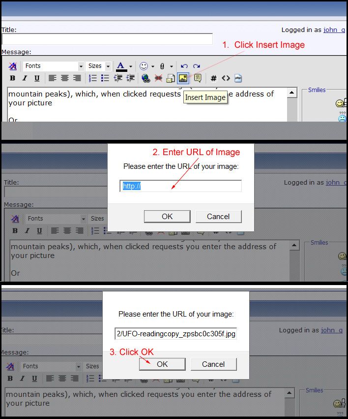
            I know it's off topic guy's, but how do you use IMG to put pic's in posts instead of attachments? God i wish i had of learn't how to use computers.

            Comment


            • Originally posted by Cornboy 555 View Post
              I know it's off topic guy's, but how do you use IMG to put pic's in posts instead of attachments? God i wish i had of learn't how to use computers.

              Comment


              • Originally posted by Ufopolitics View Post
                Hey Machine,

                Well, I think 17 gauge is a perfect approach here ..right in between 18-16 awg.

                Related to resistance check the accuracy of your meters by measuring any LOW resistor of known value...see if it read them right.
                It seems kind of low though...I get 0.6 to 0.8...somewhere in there...but then you've got a thicker wire...that could make the 0.1 to 0.3 difference...But no sweat my friend...IF the readings are fine...it is ok...since the only way to lower Amperage is by connecting them in series...BUT...Not in the way everybody may think at first glance at connections...

                Have to realize that once you get all four at front and four cables at rear of Motor....there are a lot of possibilities to be connected between them...but I will let you all a "riddle"...


                This is very important here...if you set them in series...but using a "conventional way"...it will rest power and speed to the Motor...and yes...amperage will be low...but then...it will not spin Generator properly...and I am talking about a difference of around 800 to 1000 RPM's...and a few pounds of less torque...

                I would like to hear or see (better see it in a graphic...) some of your suggestions of "How to attach them in series"...based on the above paragraphs...then I will know if you are already "getting this whole idea right"...


                Regards Machine , regards to all


                Ufopolitics
                Hello UFO, Machine, All

                Measuring Low Resistance Values with Cheap Digital Meters

                I just carried out following exercise in measuring Low Resistance using

                Cheap Meter CEN-TECH Model 37772
                Fluke Meter 17B (as reference)


                Method when using cheap meter


                Make sure battery in the meter is OK

                Set the meter on the cheap meter on the lowest OHM's Range (in my case it was 200 Ohm)

                First just try to measure the resistance of the leads only (this is our calibration step).

                My cheap meter displayed this as 0.5 OHM (This will be our OFF SET)

                Fluke 17B just displayed 000.0 OHM on the Auto Range

                First measurement example

                Spool of 400 ft of 18AWG magnet wire
                cheap meter showed this to be 3.0 OHM
                Actual Value of Spool of wire resistance = 3.0 OHM – 0.5 OHM (Offset) = 2.5 OHM
                This was confirmed on my FLUKE 17B meter to be also = 2.5 OHM

                Second measurement example

                Resistor 3.3 OHM 5% Metal oxide type
                Cheap Meter reads as 3.8 OHM
                Corrected value = 3.8 OHM – 0.5 OHM Offset = 3.3 OHM
                Fluke 14B reads as 3.3 OHM

                I hope these examples help as I too have quite a few of cheap and cheaper meters.
                I keep them to use in a situation where I might end up sacrificing them.

                Best wishes

                Warmest regards


                light

                Comment


                • hello lightworker

                  Thanks for tips.
                  I did use new battery in dmm. short at leads measured 0-.1, coils were .4, therefore real ohms would be .3, thats really low. It had to be 18 ga i used. I don't know , We'll see what happens, I have some 6 ga, so i will be test firing this weekend.

                  Machine

                  Comment


                  • Hello All
                    This is a simple sheet of COPPER MAGNET WIRE DATA that might prove useful. Its an edited version of some larger ref.

                    I know there are lots of extensive references out there. Sometimes I just want have a quick look for a particular wire data.


                    Here is also a PDF Link

                    https://www.dropbox.com/s/j3k4ab6bwp...ire%20Data.pdf

                    Warmest regards


                    light

                    Comment


                    • @ all
                      those cheap meters are fine if you open the back and adjust pot so meter reed correct to known amount. They just are not adjusted correctly. You should do this as it is too easy to forget adjustment and take incorrect reading. Even a good scope need calibration sometimes.
                      Dana
                      "Today's scientist have substituted mathematics for experiments and they wander off through equation after equation and eventually build a structure which has no relation to reality."
                      Nikola Tesla

                      Comment


                      • Originally posted by machinealive View Post
                        hello lightworker

                        Thanks for tips.
                        I did use new battery in dmm. short at leads measured 0-.1, coils were .4, therefore real ohms would be .3, thats really low. It had to be 18 ga i used. I don't know , We'll see what happens, I have some 6 ga, so i will be test firing this weekend.

                        Machine
                        Hello Machine, UFO
                        about two days back as I was still waiting for missing and damaged imperial hardware items, I started calculating amount of wire required for winding this motor (Post #3256).

                        Wanted an idea if needed to order #18 AWG wire. Any ordering part numbers for the #18 AWG wire will be appreciated (for example EIS) if possible.
                        The estimates of the wire length are on the higher side. Here is an example:

                        If Number of Turns per Quadrant (7 Poles) =13, then wire total length = 849.33 ft (Wound Asymmetric Armature UFO)


                        Working through figures, for each NS pair of coils the resistance seems to come out at about 0.2 OHM. This is really low.

                        Well I am now somewhat puzzled at this calculated result.

                        I am looking forward my hardware to arrive and start with the real measurements.

                        Machine as UFO said, "After careful assembly", best to a test run.

                        All the best


                        Warmest regards

                        light

                        Comment


                        • Originally posted by prochiro View Post
                          @ all
                          those cheap meters are fine if you open the back and adjust pot so meter reed correct to known amount. They just are not adjusted correctly. You should do this as it is too easy to forget adjustment and take incorrect reading. Even a good scope need calibration sometimes.
                          Dana
                          Many Thanks Dana

                          You are correct on that. All equipment must be calibrated.
                          In industry as you know they recalibrate equipment after certain time period.
                          At home one tends to slack somewhat.
                          I will calibrate my meters.

                          All the best


                          Warmest regards

                          light

                          Comment


                          • Thanks.

                            Originally posted by john_g View Post


                            Thanks, John G, i will give it a go.

                            Regards Cornboy.

                            Comment


                            • Tried.

                              Hello John G, tried it once and didn't come through, so i deleted the post.

                              God, what a computer dummy, What's a URL?

                              Comment


                              • Cornboy 555
                                A URL is the internet location that the item you want to show is stored at. I store mine in Photobucket. Search for photobucket and register, it is free. Then upload the picture into photobucket and copy the address of it into your buffer,(with Ctrl/C. Then start your post in EF and follow John-g's directions. Cant wait to see what you have to show.
                                Dana
                                "Today's scientist have substituted mathematics for experiments and they wander off through equation after equation and eventually build a structure which has no relation to reality."
                                Nikola Tesla

                                Comment

                                Working...
                                X