Announcement

Collapse
No announcement yet.

My Asymmetric Electrodynamic Machines

Collapse
X
 
  • Filter
  • Time
  • Show
Clear All
new posts

  • Am Back!

    Hello to All,

    Thanks Ewizard...it was exactly My Cache...besides I deleted history, cookies, brownies and chocolate chips...

    Machine great run there!!...Your Generator runs excellente!!
    Bravo Man, way to wind'em!!
    I could leave you here and you sure will train all this guys...

    Guys, about the winding mode...I display it clearly on My Asymmetric Winding Part 1... video...

    I always use this Method to Wind ALL My Machines...and as you all know...they ALL work...

    Now I follow the Positive Direction from the Positive Wire from the Positive Side Commutator...towards my fingers...sometimes "I" Direction tends to confusion...So I made it the way I do it below guiding by Positive (+) Side Comm..

    [IMG][/IMG]


    Now, That Coil shown there is a WHOLE PAIR ...in our Imperial (for example), Meaning it CONTAINS P1 South and P1 North...now, use your Imagination... to virtually "bend" that Steel Bar...in a "V" Shape and make them Your Armature Groups of Poles to be wounded N & S...

    And that Applies to every single model I have displayed here...except the Three Pole...that is just a STRAIGHT COIL for each Pole, and ALL South are aiming towards shaft...

    Thanks John for clearing this concepts...and reminding them of my winding video...and YES...IF You turn that Armature Upside down...and start winding from Negative side...Motor will NOT RUN...So always keep a Positive commutator UP...as a reference to your winding start point for every Pair there.

    Regards


    Ufopolitics
    Principles for the Development of a Complete Mind: Study the science of art. Study the art of science. Develop your senses- especially learn how to see. Realize that everything connects to everything else.― Leonardo da Vinci

    Comment


    • Awesome Winding!!

      Originally posted by machinealive View Post

      Hello Machine!


      Excellent run!...Brilliant Winding My Friend!
      So Far you are My BEST Imperial Student!!...

      Now Generator runs excellent...very strong, a bit slower...but it will have MUCH Torque...realize you've got three bisectors South and Three Bisectors North at each Pair...so, yes...it is stronger...and as you noted, much less sparking...since you have more resistance there...more turns per coil.

      Now get ready to run that Baby as a Generator...well make it in a way both could connect face to face...3/4 shaft to 3/4 shaft...and IF Possible use a Fixed Universal Joint...NOT FLEXIBLE...that way, before you make the stands...connect both Machines Firmly and very Tight by front shafts...test free rotation...and then go for making its Base to bolt them down...

      If You think about this way...Once You connect both Machines tight by front shafts...their Rear Bearings no longer have the same stress, resting at rear housings...they have become now stronger by their two front bearings...get What I mean, Jelly Bean?...

      Now, the tests you could make there...and the different possibilities are excellent...

      1- Connect Asymm Motor to Asymm Generator...then:

      1a-"Take One"...Make it so Motor Runs Generator...Measure Generator Output by connecting ALL Coils there in series...Positive with Negative...like Batteries......Make sure you do not connect SAME BRUSH TERMINALS...or will create a ZERO ENERGY LOOP...

      1b-"Take Two" Have Generator run Motor and check Motor Output doing same series connections of their terminals...

      Measure RPM's at all time of tests...

      Remember that another testing would be gathering the Motor Output Terminal and adding it to Generator Terminal...

      So, I am very sure You are going to Pulse Feed this Machines...RIGHT?
      I know you are going to use your "Jumbo" Controller...Huh?...

      Make sure when running Motor...You protect those FET's...remember your resistance is low...now I will give you a great Tip here...

      Run Motor FIRST LINEAR/STRAIGHT from Batteries for a bit...Three Five Minutes run, with parallel connections like factory...black to black...Red to Red...and warm up those Coils...till they get to around 150º-175º F...And you know what would happen?...Take a reading at your resistance per pairs (disconnect them and just measure one terminal Gate...so you just read One Pair at a time)...and you will notice your resistance, because of heated coils...have risen by double or more their original values.

      THEN...You will be safer running them with your Pulse Controller, since they are Higher/Safer Resistance for your FET's...
      Have Fun Man!!...You deserve it!


      Regards


      Ufopolitics
      Last edited by Ufopolitics; 01-12-2013, 10:57 PM.
      Principles for the Development of a Complete Mind: Study the science of art. Study the art of science. Develop your senses- especially learn how to see. Realize that everything connects to everything else.― Leonardo da Vinci

      Comment


      • Hello Arch!

        Originally posted by arch chicken View Post
        in have a notion

        to UFO POLITICS

        sir, correct me if i am wrong.....

        i am very interested in the asymmetric generator
        So, You are "VERY" Interested...?...Right?

        So...You have Money?...Mean $$$???


        Sorry, but..."No Money no Laundry..."

        Joking!!...

        as i see, we have a asymmetric motor turning a symmetric generator with very good results...if not ou....
        a symmetric generator is stiff....
        an asymmetric generator is the exact opposite, it is loose?
        Not only "loose"...but it will assist rotation...

        so, my notion....one could then also turn the asymmetric generator with a symmetric motor and still get very good results? or am i barking skywards???
        Yes, absolutely and definitively you could do just that...

        And "even better" If You get a beefy Coil...Pulse it, get some fast diodes and feed symmetric motor from the Radiant Reversed flow (My First Thread here)......Then you will be using very little Input pulsed to that Coil...using the Radiant Amplified Higher Frequencies...and run that Motor Cool...No Sparks...and very "smooth"...

        i am always learning,,, and now own six imperial motors that needs modification...i have wired and done one motor to assymetric system, same as yours...what a amazing machine to work with.....am following on the generator and has started to convert it to same system..
        WOW!!...You've got SIX Imperial UFO Kits??!!
        What you wanna do?...start selling them?...

        Yes, it is an amazing Machine right?...am very happy that you liked them.


        sorry if i disturbed you since i am curious and not electrically trained....dummy really, i have a hard time following the electrical discussion between you and Mr John stone.....is there a easier way to do the electrical side........??

        regards
        ARCH CHICKEN
        Never "disturbed Me"...never...it is a pleasure to hear again from You My Friend!

        Hope we could see some pictures and ...A Video of that Machine running...Roaring and sparking will be even BETTER!!

        Regards and Take Care


        Ufopolitics
        Principles for the Development of a Complete Mind: Study the science of art. Study the art of science. Develop your senses- especially learn how to see. Realize that everything connects to everything else.― Leonardo da Vinci

        Comment


        • Motor Generator Connections

          Originally posted by machinealive View Post
          Hey Machine,


          I made a Diagram of Your Motor and Generator Future Connections...
          I had displayed here before, but related to the small Radio Shack Motor...However, there is a big difference since we have here Four Brush System....and a Huge Difference in Size...


          [IMG][/IMG]


          Now, main thing We all could get lost here...is that Your Motor would be driving your Generator...and Your Motor turns CCW when right connections are made like you already did...Now, Your Generator is wound same way...so it also turns CCW IF You feed it same way as your Motor...BUT...When your Motor would be turning it...it will be forced to turn opposite...so, everything changes there...and if you look at your Generator Outputs on Diagram...they are reversed...and You could check on that in Real Time Tests...

          I set this Connections for Motor Input, as they come from Factory...meaning, red to red and black to black...or Parallel Input at 180º Apart by P1 and P15...

          While, I set the Motor Output in Series between P8-P22...Also apart by 180º...

          Remember this Picture below,(I know you know exactly how it is...I am just presenting this in order that others replicating the Imperial, but not as ahead as you are...will understand it also):

          [IMG][/IMG]


          NOW...THE FUN IS ABOUT TO START...MY FRIEND...


          According to First Diagram You see ALL OUTPUTS...From Motor and Generator...So...FIRST take them for a spin just like that...and read both Outputs separate and simultaneously (Two DMM Please) ...Motor and Generator...Add a Load (Incandescent Bulb) if You please...and also measure Amps...

          After that Run...NOW Join Motor Output and Generator Output...in SERIES CONNECTION...Meaning Plus to Minus...then get your Plus Minus from each ends...(Join Motor Negative Out to Gen Positive Out, they are right next to each others at Diagram above)...

          PLEASE, USE SIX (6) GAUGE WIRE FOR ALL THIS CONNECTIONS BETWEEN MACHINES!!
          I saw in your Video...You are using lower Gauge Wires...Please don't DO that HERE!


          Now prior to this...please get a very nice Parallel Capacitor Bank...of say 8 or 10 of 1000 uF each and 240V...Electrolytic, Polarized... (The More Capacitance the More the Fun...)...and connect them Parallel to Both Motor-Generator Outputs...Run them for a while, If Pulsing Motor...take it Close to Max RPM's...use an external Fan...Measure Total Output at Cap Bank...and have fun...Now, when you stop feeding Motor from Input...take a seat, relax...and watch them keep going...

          NOW, YOU BETTER make sure You FILM THIS TESTS...I WANT TO WATCH THEM GO!!


          Regards


          Ufopolitics
          Last edited by Ufopolitics; 01-13-2013, 01:50 AM.
          Principles for the Development of a Complete Mind: Study the science of art. Study the art of science. Develop your senses- especially learn how to see. Realize that everything connects to everything else.― Leonardo da Vinci

          Comment


          • @UFO
            You are keeping ahead of us as usual and its great. I should have mine running mid next week when the rotor has cooled. I have ordered another kit and am hot on your trail.

            The bearings that came with motor are rated for 12000 RPM with good static and dynamic levels. If we just set in a screw tightener as you suggested, with (no) wear in our bearing ports, do you think that is enough??? I think it may be....
            Dana

            PS I saw your answer and will get different bearings pronto.
            Last edited by prochiro; 01-13-2013, 02:40 AM. Reason: PS
            "Today's scientist have substituted mathematics for experiments and they wander off through equation after equation and eventually build a structure which has no relation to reality."
            Nikola Tesla

            Comment


            • Attacking the RS winding

              Fantastic info on winding guys, let me post some more results I have and get some more responses on my toy motor while you guys try to built that home power plant. What a dichotomy!

              So here is my favorite picture on how to wind a 5-pole motor asymmetrically.


              Before I can write intelligently about my findings, let me set out my annotations:


              Commutator annotation C1 would indicate the front commutator and c1 (lowercase) the back commutator in alignment with C1. This will be called the front view.

              On the last winding, the only one that you can reasonable inspect with a very good magnifying glass I am certain I went from commutator C4 up to Slot S2 and wound CCW ~40 turns around Poles 1 & 2, and then transitioned to CW winding around poles 4 & 5 coming out very nicely to commutator c4.

              In the unannotated winding diagram, it starts at P1 and crosses under to Slot S4, wraps CCW around what would be Poles 4 & 3.

              Subtracting (P1 - 2 = P4) from all these numbers confirms and matches this diagram. So apparently I am OK at least on the last winding.

              Now lets look at the polarity. The diagram shows its pole 1-2 as a south pole. But I hook up +3 v to the C4 commutator and it does show the opposite, North Pole. I have to read Mr Stone's post to see if I can find some understanding on polarity. I think I read somewhere that the Left-hand rule is applied with the fingers identifying the current flow the thumb should be North. I just get confused about it being the opposite direction of the actual flow of electrons though??? But the motor doesn't really care it will just turn the other way? But in any case I think my pole is a North pole there not South.


              Poles 4-5 with this test jig is not very accessible but this seems to get satisfatory results showing the opposite pole there, South.


              Other windings seem to respond the same as I rotate the rotor.

              So does anything seem incorrect so far to anyone?

              Thanks. Maybe one of you guys will sell me one of those home power plants...
              Attached Files
              Last edited by sampojo; 01-13-2013, 02:54 AM.
              Up, Up and Away

              Comment


              • Hello UFO, everyone

                Sorry I did not take the RPM's when I shot the test vid, the sparking from the motor test was "wild" and "big". Really, could you see how much sparking there was. I was sure that would have to be tuned some, so UFO, you think that the increase in heat will increase resistance enough to reduce that, I hope you' re right, maybe after brushes seat some, it will help also.
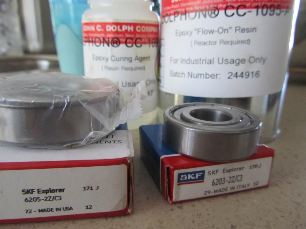
                I removed the bearings, resined it, and now is cooling, tomorrow I get the new steel bearings on. Then I'm gonna turn the comms a smidge, and get every bit of resin off from in between comm elements, it will act like glass and destroy brushes, right , then I retest continuity of the coils, and solder.
                Here's a good link for all your resin needs, all of them.
                Coatings, Compounds. Varnish - John C. Dolph Company

                UFO, all motor and gen connections were same ga as imperial came stock, 6 ga I believe, the battery connections were 8 ga, I did not have enough wire at home to make new ones, but I will, it was just a quick test.

                So, you are saying I should try with motor input parallel and output in series, that will be serious low resistance at motor input. In my test, motor brushes were in series, gen brushes were not connected.

                Yes UFO, we need some big old capacitors. What about motor run caps? I have quite a few of those.

                Machine

                Comment


                • impedance test results requested P115

                  Originally posted by Ufopolitics View Post
                  Hello Sampojo,

                  Ok, make a test on Rotor...

                  Second test:

                  Test for Ground leak on each with continuity meter...one element and ground...on all five.


                  Let me know...

                  Regards

                  Ufopolitics
                  OK, so impedance between coils runs from about 1.5M to 5M ohms, thought I saw an 88k once or twice but could not reproduce it. Just had the Ohm meter on leads between the motor and generator coil. Between any coil and the rotor or shaft I go no indication of any sensitivity in the meter, total open circuit.

                  So should I just tear the motor down and try again? I re-used the old wire which had the nicks in it at all the old commutator locations. I saw an interesting post around page 50 saying you should use 32 gauge if you want to put an asymmetric RS motor amp range down near what the amp range of the symmetrical motor. I could try that as I would like to modify a home appliance I have that uses this motor and I think it would be too powerful. I am interested in the longer battery life it should give.

                  Thanks UFO!
                  Up, Up and Away

                  Comment


                  • Oops...

                    Originally posted by machinealive View Post
                    Hello UFO, everyone

                    Sorry I did not take the RPM's when I shot the test vid, the sparking from the motor test was "wild" and "big". Really, could you see how much sparking there was. I was sure that would have to be tuned some, so UFO, you think that the increase in heat will increase resistance enough to reduce that, I hope you' re right, maybe after brushes seat some, it will help also.
                    I removed the bearings, resined it, and now is cooling, tomorrow I get the new steel bearings on. Then I'm gonna turn the comms a smidge, and get every bit of resin off from in between comm elements, it will act like glass and destroy brushes, right , then I retest continuity of the coils, and solder.
                    Here's a good link for all your resin needs, all of them.
                    Coatings, Compounds. Varnish - John C. Dolph Company

                    UFO, all motor and gen connections were same ga as imperial came stock, 6 ga I believe, the battery connections were 8 ga, I did not have enough wire at home to make new ones, but I will, it was just a quick test.

                    So, you are saying I should try with motor input parallel and output in series, that will be serious low resistance at motor input. In my test, motor brushes were in series, gen brushes were not connected.

                    Yes UFO, we need some big old capacitors. What about motor run caps? I have quite a few of those.

                    Machine

                    Hello Machine,

                    In my test, motor brushes were in series, gen brushes were not connected.
                    Oops!...Then NOPE, DON'T Connect them in Parallel...SERIES INPUT PLEASE!...

                    Did You measure Resistance in Series at Input?

                    Yes I saw it... they were sparking heavy!

                    Well, like you have said...brushes need to seat in...that would reduce it some ...
                    And if you notice...after turning off...sparks continue...did you see the "Post Sparking"?

                    Try to make a run with a Load at Generator, an Incandescent 120 V Bulb...It will not fully lit...but will reduce sparks.

                    Motor Caps are AC...as they are low capacitance...but give it a try...it will not hurt anything there...as they will reduce sparking also.

                    I am preparing a Couple of more Diagrams on Full Output and for a Self Running (for a little bit, don't get too excited though) with Caps...However, even a few seconds running on Caps is something when we are talking about two huge Machines like this ones.


                    Now, resin getting in between commutator gaps is not good...no, they will not crystallize to damage Brushes or commutators...what will happen...is that they will get carbon dust impregnated...and end up conducting between elements pairs...


                    Regards


                    Ufopolitics
                    Principles for the Development of a Complete Mind: Study the science of art. Study the art of science. Develop your senses- especially learn how to see. Realize that everything connects to everything else.― Leonardo da Vinci

                    Comment


                    • Rs-p5

                      Originally posted by sampojo View Post
                      OK, so impedance between coils runs from about 1.5M to 5M ohms, thought I saw an 88k once or twice but could not reproduce it. Just had the Ohm meter on leads between the motor and generator coil. Between any coil and the rotor or shaft I go no indication of any sensitivity in the meter, total open circuit.

                      So should I just tear the motor down and try again? I re-used the old wire which had the nicks in it at all the old commutator locations. I saw an interesting post around page 50 saying you should use 32 gauge if you want to put an asymmetric RS motor amp range down near what the amp range of the symmetrical motor. I could try that as I would like to modify a home appliance I have that uses this motor and I think it would be too powerful. I am interested in the longer battery life it should give.

                      Thanks UFO!
                      Hello Sampojo,


                      Don't take it apart...run it...take it for a spin Man!!
                      According to all your pic's, and tests...it should run great now!


                      [IMG][/IMG]

                      After assembled...it should look something like this Uh?...


                      Regards


                      Ufopolitics
                      Principles for the Development of a Complete Mind: Study the science of art. Study the art of science. Develop your senses- especially learn how to see. Realize that everything connects to everything else.― Leonardo da Vinci

                      Comment


                      • Thanks again UFO, for all your help and knowledge, can't wait to get at this tomorrow. I think the series resistance was .5-.6, it was posted back a few pages, I will keep motor input at sereis and motor output at series as well.

                        Comment


                        • @UFO
                          After looking for better Imp. bearings I got confused. Are there preferred bearing numbers that I can locate?
                          Dana
                          "Today's scientist have substituted mathematics for experiments and they wander off through equation after equation and eventually build a structure which has no relation to reality."
                          Nikola Tesla

                          Comment


                          • Rear Bearing...

                            Originally posted by prochiro View Post
                            @UFO
                            After looking for better Imp. bearings I got confused. Are there preferred bearing numbers that I can locate?
                            Dana

                            Hey Dana,

                            Yes, the Rear Bearing Number is:

                            NTN 6203LLH C3

                            Found it for you... at your preferred shopping Mall...GRAINGER's...

                            NTN Radial Bearing, 17mm Bore, 40mm OD - Radial Ball Bearings - 4ZXE9|6203LLUC3/L627 - Grainger Industrial Supply

                            It is the same I've got...Canadian, just like Machine Alive...So it should be good right?...

                            EDIT 1...Nope it is not!...that one goes only 12,000...so have to look for it.

                            For some reason have the letter U instead have an H...so not same.

                            Regards

                            Ufopolitics
                            Last edited by Ufopolitics; 01-13-2013, 05:17 AM.
                            Principles for the Development of a Complete Mind: Study the science of art. Study the art of science. Develop your senses- especially learn how to see. Realize that everything connects to everything else.― Leonardo da Vinci

                            Comment


                            • I Am, Canadian

                              Here are my bearings #

                              Comment


                              • FULL POWER and a SELF Runner...Config

                                Originally posted by machinealive View Post
                                Thanks again UFO, for all your help and knowledge, can't wait to get at this tomorrow. I think the series resistance was .5-.6, it was posted back a few pages, I will keep motor input at series and motor output at series as well.
                                Hey Machine,

                                Here are a Couple of Tests...For Excitement...

                                Now, I have performed at smaller scale the "Full Power"One...it works great, and the Motors were small type 550 Body...so here You have in your side the Fly Wheel Effect of two Huge Mass Spinning Rotors, and hopefully they will create the enough "delay" to "jump that bridge"...even for a bit...Now the "Secret" is to get them spinning fast for a while...allow caps to charge good...and keep Meters Monitoring Voltages at all Plus-Minus circles I have set there...Meaning Four Meters measuring Voltages...Good Luck!

                                Now, Caps need to be High Capacity so it gives you a greater time delay effect...I have tried with Two of 22,000 Uf...but 85-90 Volts (I was testing low Lipo's at 36Volts...and pulsing Input).

                                IMPORTANT: There would be some Adjustment/Tests you may need to do to Generator...to get the best timing possible, and I have forgotten about this, sorry, but "easy fix"...You must Test Generator to Run Counter to Motor (CW) when applying Polarity Reversed as it goes to Motor (the same way/polarity Generator will Output)...then you will have an excellent set there...Then Small Adjust moves for faster speed...check it with IR Tach...

                                Generator Brushes will be connected as Diagram shows...(Note that the Pairs Numbers Sequence are set different as Motor, Because they are opposite!) so you will be powering/Feeding it from what would be its Full Output Polarity.

                                If Generator still turns CCW when connecting it that way I wrote above...then you will have to do some more adjust and You let me know

                                However, I do not think you will have any problems at all...it should turn opposite at first Test Run.


                                The Point here is...Generator will be turning opposite to Motor, and it will be energizing its Coils as well...opposite, therefore, if it is set in timing exactly as Motor...it will assist Motor...and we want to make sure it is set that way...We want "All the Forces on our side" here...

                                FULL POWER OUT...


                                [IMG][/IMG]


                                AND...THE SELF RUNNER


                                [IMG][/IMG]

                                Now, Once You get a Good Top Voltage at Cap Bank (From previous tests You MUST know how much Total Your Generator alone produced, and charged Caps up to...when Motor was at Full speed)

                                Do not connect any Loads on Generator Out...leave it open.

                                Then You Close that switch...Motor will speed Up first...as Cap's reading will decay...hopefully, just a bit, till Machines come to an Equalization
                                Exchange of Energy...Then watch Your Feeding Batteries Voltage...If Going Up or Down (They should stabilize to a steady reading and not coming down, just pulsing at 0.Volts)...Then, disconnect them and watch what happens...


                                Good testing!!


                                Regards


                                Ufopolitics

                                P.D: I have edited and analyzed this Post for Hours, and many times...making sure everything I have written is correct and perfect, and not writing too much as to confuse you, however, any questions, please ask...
                                Regards
                                Last edited by Ufopolitics; 01-13-2013, 08:02 AM.
                                Principles for the Development of a Complete Mind: Study the science of art. Study the art of science. Develop your senses- especially learn how to see. Realize that everything connects to everything else.― Leonardo da Vinci

                                Comment

                                Working...
                                X