Reviewing Times...
Hello to All,
This Post refers to ALL My Machines in General...like "An Upgrade"...should I say...
However, I want to emphasize on Imperial Replications going on now, since they handle so High Amperage and Sparking at Commutators...this is the End of that Issue...
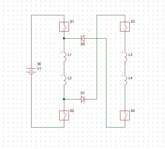
This also refers to the Main Material I have displayed previously on My other Thread...a while back, when We were Pulsing a Static Coil and getting reversed Radiant Flow through a Couple of Ultra-fast Rectifiers like this:
[IMG] [/IMG]
For all those following Me since then...know that the Amperage at our "Hot Side" was pretty low, while we were loading Heavy CFL's of quite High Wattage and even HD Metal Halide Bulb Assembly (Transformers and Starters) as could also be seen on my Video here:
LIGHTING HID BULB ASSY WITH RADIANT ENERGY - YouTube
Well, it's been quite a while since then...
And We all got involved in winding Motors...and Generators...making stands...testing Torque...Amps-Volts...so it seems we all forgot (including myself, of course)...about this great set up here.
And actually the fact is...that those Solid Static Coils were nothing more than a reproduction of My Machines Circuit...but Static, Not Dynamic.
You guys have no idea How Much I have "traveled" back and forth from so many different set ups...that go as far as My Original Shaft Less Machines Structures, that I applied for a Patent around 16 years ago...
The answer to the huge sparking and great currents...was, in the very beginning what trigger Me to find the Radiant Energy Field, developing within those Coils...and now we have them again...and honestly...I completely forgot...about my first Thread development...incredible...isn't it?...well, is Human normal errors right?...
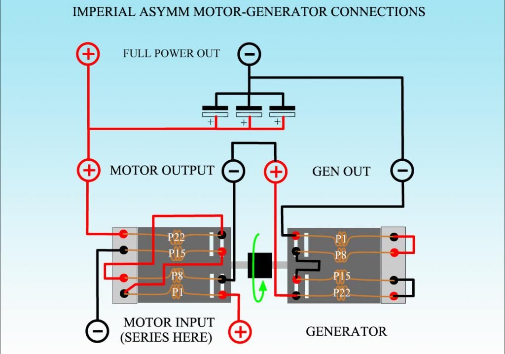
So I have here a Diagram related to the Imperial Asymmetric Conversion...reflecting the FLOW...as it occurs in ALL of this Asymmetrical Machines...BUT, Now Rectified, in order to "Re-Direct, Re Route" those heavy reversed flows to continue their supposed path...
[IMG] [/IMG]
Here I am just feeding Input Through P1 and P15 Gate Terminals...so We get a Generator Output through P8 and P22 Gates (Note that I am NOT referring to Pair Coils...BUT Gates, and Gates allow the Continuous Flow from ALL Coils Pairs in the Armature)...So, this is the simple form, of just Two Inputs, Two Outputs...
The Shaded Areas in Black (at Positive Commutator) and Red (at Negative Commutator), represents the excess flow getting into our Input Gates from the reversed Radiant Fields or Back EMF...or else...as you please to call them...
Now take a look at My First Picture here...a single Static Coil...being pulsed by a FET...and through two diodes rectifying/controlling the reversed flow at Blue arrow...that was where we all connected loads...while our amperage at Hot/Red side was very low...
If You look at this last diagram...and check out D1a and D2a...related to P1 COIL (wound and fed from Pos Comm to Neg Comm)...we will have exactly the same arrangement as in My First Circuit...just freeze it in Time and Space...don't let the Motor run...please...
Oh!...but there is not a Pulsed FET there feeding it...right?...We are feeding it linear/straight...so what happens when you take the "Pause" off and keep playing that video?...P1 COIL Disconnects from Gate Feed P1...and starts a reversal process...till it "lands" at Gate P22 (Note Rotation is CCW) where it discharges an enhanced and amplified flow because of traveling within a Magnetic Field from Stators...remember Induction?...BUT P1 COIL is NOT the only one there...but 27 more P COILS...So here just started a Spiral of Amplified Flows Process that Increases as we increase speed (RPM's) of Armature...
That Reversed Flow..."Leaks" back into our Input Gates, creating a heavy colliding point at those brushes and commutator elements...heavy sparks...high amperage...terrible isn't it?
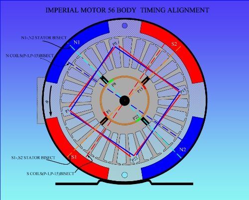
Well any of you that have constructed one of my motors (ANYONE)...could verify that D1a and D2a will show a reversed reading when Motor is running...and as a matter of fact I have displayed

 such diagram here...:
[IMG] [/IMG]
However, here it is displayed at Generator Side...BUT NO MATTER, Do it at your Battery Input...it will ALSO SHOW IT CLEARLY.
So, what can we do?...simple...set those Diodes as D1,D2,D3 and D4 as they are connected at Diagram...Jumping to next brush all the reversed flow to our outputs...
Now, this is COMPLETELY RELATED TO OUR ROTATION SENSE...as note lower Commutator has Diodes reversed since they are forward biasing Positive Flow.
Simple wasn't it?
I will be uploading a Test Video with Imperial...with Diodes connected...as we take our Amperage-Voltage readings...
Now, when We Feed ALSO from Generator stage...like I have done before through all those tests...

 ...then the Reversed Flow gets Amplified "like if there is no Tomorrow"...Galore...and I will be rendering another Diagram on related Feed...
And...This is Linear Straight Feed...Not Pulsing this Machines Yet...
Regards
Ufopolitics
Hello to All,
This Post refers to ALL My Machines in General...like "An Upgrade"...should I say...
However, I want to emphasize on Imperial Replications going on now, since they handle so High Amperage and Sparking at Commutators...this is the End of that Issue...

This also refers to the Main Material I have displayed previously on My other Thread...a while back, when We were Pulsing a Static Coil and getting reversed Radiant Flow through a Couple of Ultra-fast Rectifiers like this:
[IMG]
 [/IMG]
For all those following Me since then...know that the Amperage at our "Hot Side" was pretty low, while we were loading Heavy CFL's of quite High Wattage and even HD Metal Halide Bulb Assembly (Transformers and Starters) as could also be seen on my Video here:
LIGHTING HID BULB ASSY WITH RADIANT ENERGY - YouTube
Well, it's been quite a while since then...
And We all got involved in winding Motors...and Generators...making stands...testing Torque...Amps-Volts...so it seems we all forgot (including myself, of course)...about this great set up here.
And actually the fact is...that those Solid Static Coils were nothing more than a reproduction of My Machines Circuit...but Static, Not Dynamic.
You guys have no idea How Much I have "traveled" back and forth from so many different set ups...that go as far as My Original Shaft Less Machines Structures, that I applied for a Patent around 16 years ago...
The answer to the huge sparking and great currents...was, in the very beginning what trigger Me to find the Radiant Energy Field, developing within those Coils...and now we have them again...and honestly...I completely forgot...about my first Thread development...incredible...isn't it?...well, is Human normal errors right?...
So I have here a Diagram related to the Imperial Asymmetric Conversion...reflecting the FLOW...as it occurs in ALL of this Asymmetrical Machines...BUT, Now Rectified, in order to "Re-Direct, Re Route" those heavy reversed flows to continue their supposed path...
[IMG]
 [/IMG]
Here I am just feeding Input Through P1 and P15 Gate Terminals...so We get a Generator Output through P8 and P22 Gates (Note that I am NOT referring to Pair Coils...BUT Gates, and Gates allow the Continuous Flow from ALL Coils Pairs in the Armature)...So, this is the simple form, of just Two Inputs, Two Outputs...
The Shaded Areas in Black (at Positive Commutator) and Red (at Negative Commutator), represents the excess flow getting into our Input Gates from the reversed Radiant Fields or Back EMF...or else...as you please to call them...

Now take a look at My First Picture here...a single Static Coil...being pulsed by a FET...and through two diodes rectifying/controlling the reversed flow at Blue arrow...that was where we all connected loads...while our amperage at Hot/Red side was very low...

If You look at this last diagram...and check out D1a and D2a...related to P1 COIL (wound and fed from Pos Comm to Neg Comm)...we will have exactly the same arrangement as in My First Circuit...just freeze it in Time and Space...don't let the Motor run...please...

Oh!...but there is not a Pulsed FET there feeding it...right?...We are feeding it linear/straight...so what happens when you take the "Pause" off and keep playing that video?...P1 COIL Disconnects from Gate Feed P1...and starts a reversal process...till it "lands" at Gate P22 (Note Rotation is CCW) where it discharges an enhanced and amplified flow because of traveling within a Magnetic Field from Stators...remember Induction?...BUT P1 COIL is NOT the only one there...but 27 more P COILS...So here just started a Spiral of Amplified Flows Process that Increases as we increase speed (RPM's) of Armature...
That Reversed Flow..."Leaks" back into our Input Gates, creating a heavy colliding point at those brushes and commutator elements...heavy sparks...high amperage...terrible isn't it?
Well any of you that have constructed one of my motors (ANYONE)...could verify that D1a and D2a will show a reversed reading when Motor is running...and as a matter of fact I have displayed


 such diagram here...:
[IMG]
 [/IMG]
However, here it is displayed at Generator Side...BUT NO MATTER, Do it at your Battery Input...it will ALSO SHOW IT CLEARLY.
So, what can we do?...simple...set those Diodes as D1,D2,D3 and D4 as they are connected at Diagram...Jumping to next brush all the reversed flow to our outputs...
Now, this is COMPLETELY RELATED TO OUR ROTATION SENSE...as note lower Commutator has Diodes reversed since they are forward biasing Positive Flow.
Simple wasn't it?
I will be uploading a Test Video with Imperial...with Diodes connected...as we take our Amperage-Voltage readings...
Now, when We Feed ALSO from Generator stage...like I have done before through all those tests...


 ...then the Reversed Flow gets Amplified "like if there is no Tomorrow"...Galore...and I will be rendering another Diagram on related Feed...
And...This is Linear Straight Feed...Not Pulsing this Machines Yet...

Regards
Ufopolitics


 )
)


Comment