 Tweet
Tweet
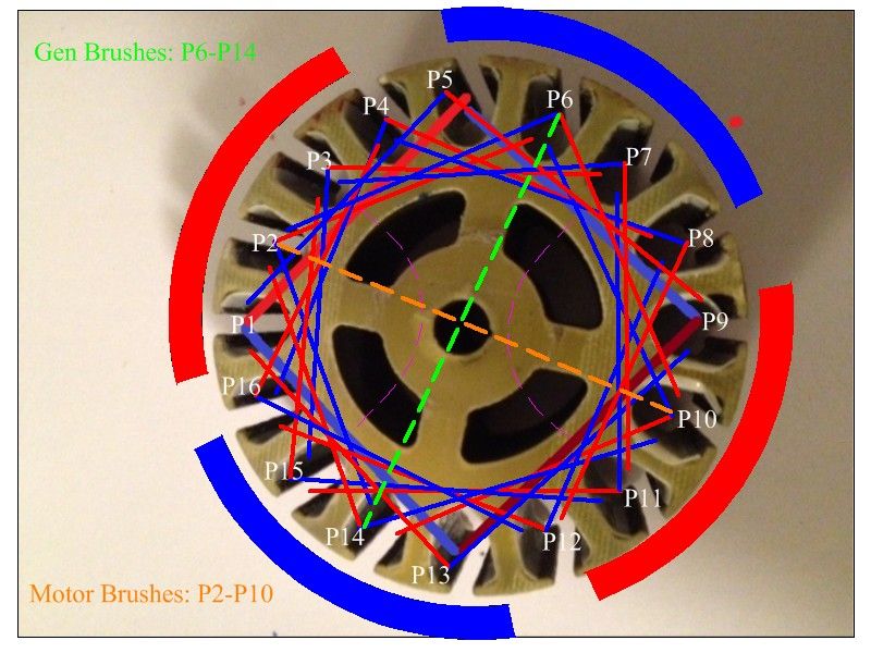
16 pole modification...
Thanks guys but if you mean this video by dave as in 11turion...
3BGS Razor scooter motor MY1016 - YouTube
Its not much of a help at all. Very hard to understand and I dont think that winding is even the same as the one UFO suggested for the 16 pole. Anyways I think I have it figured out but halfway through I decided to check the connections and the wire has chipped through its coating on the sharp corners of the outside laminates. This resulted in little shorts through out the coils....Ill be starting over tomorrow. If this has happened to anyone else it would result in a very hot motor even if it does spin....
@laserjo thanks for the idea of using 2 housings. I'd like to get it into one. Ill have to split some of the laminates off and put some more room between the commutators and laminates.
Thinking about using the extra motor housings for a 10, 12 or 20 pole motor using 5-6 plexiglass circular cut outs and drilling out spaces for the wire and maybe some capacitors. Those machines look much more interesting... I like the quad pentagon design. Cant decide which ones I like best...maybe in time I will get to test them all!


 [/IMG]
 [/IMG]
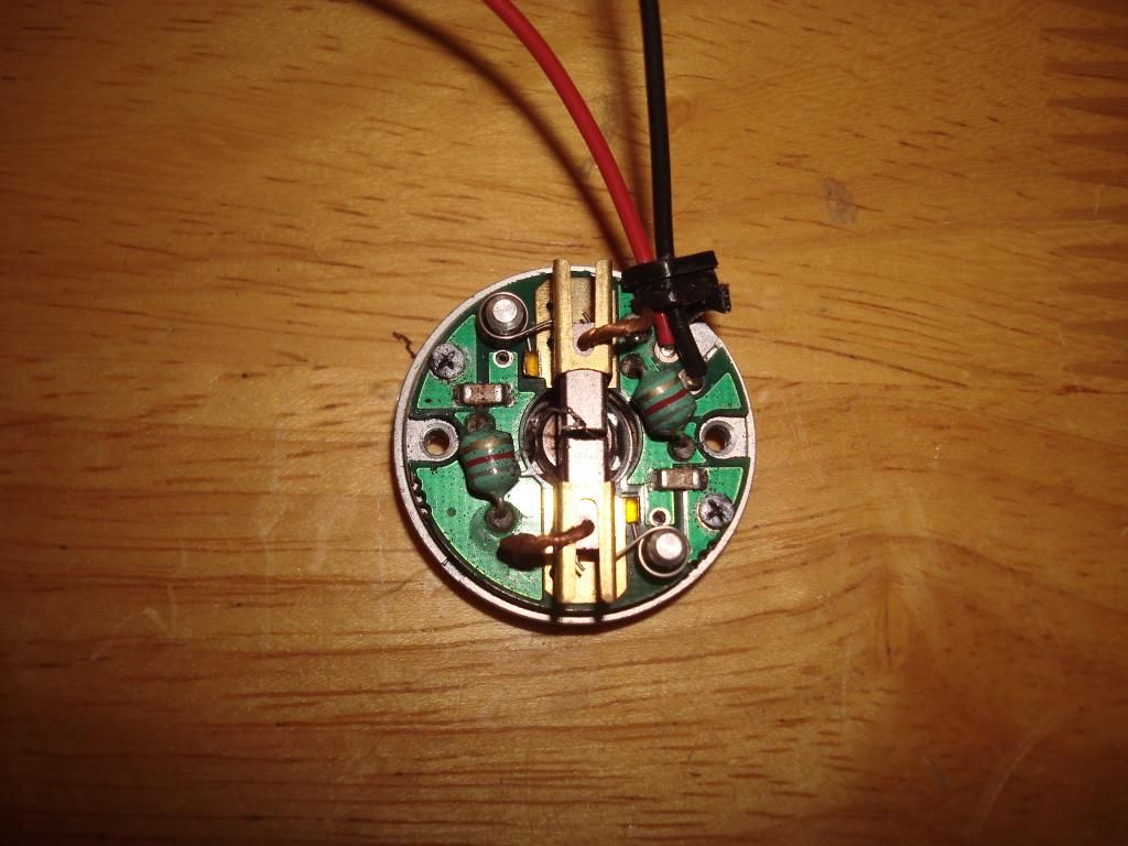 [/IMG]
 . There is no fod3180in the circuit and the SFH617A-3 does work on five volts just fine. In fact it works on much less. Now, what to do, what to do??? Well a well rested mind like yours will think of something. Good to have you back again.
 but then heard the rpm falter and then the glow and smoke. couldn't get the wires off fast enough. over 150 degF. Well couple coils shot. Don't test when you are tired!
 .
.
Comment