Announcement

Collapse
No announcement yet.

My Asymmetric Electrodynamic Machines

Collapse
X
 
  • Filter
  • Time
  • Show
Clear All
new posts

  • Somewhere I read the Tortoise can finish a race

    Thanks UFO and JS for giving me the courage to plug the Imperial in. I have just finished the 12 volt 30 minute first run of the Imperial using JohnStones full Monster circuit. After thirty minutes the fets were still without any heat. That's right, complete ambient temp. No need for fan at all with 12 volts at any frequency and 100% duty. The push button Arduino setup is sooooo handy as I have complete control of speed with LCD readout. Now I know that what you all want to see is video but 12 volts is tame. Let me get to 36 volts tomorrow and you will have video. I found that four fets gives the best performance for me as it does not stress fets at all. I do see that John was correct that it will go on two fets though. I still have to install the thermal overload shutdown program so if something does get hot it will shut down before major damage is done. John may know just what that maximum temp. should be before shutdown. See you all tomorrow. I will try to get scope shots and maybe Amps also.
    Dana
    PS: I do not think that I will sleep well tonight. Can't settle down.
    "Today's scientist have substituted mathematics for experiments and they wander off through equation after equation and eventually build a structure which has no relation to reality."
    Nikola Tesla

    Comment


    • Originally posted by prochiro View Post
      Thanks UFO and JS for giving me the courage to plug the Imperial in. I have just finished the 12 volt 30 minute first run of the Imperial using JohnStones full Monster circuit. After thirty minutes the fets were still without any heat. That's right, complete ambient temp. No need for fan at all with 12 volts at any frequency and 100% duty. The push button Arduino setup is sooooo handy as I have complete control of speed with LCD readout. Now I know that what you all want to see is video but 12 volts is tame. Let me get to 36 volts tomorrow and you will have video. I found that four fets gives the best performance for me as it does not stress fets at all. I do see that John was correct that it will go on two fets though. I still have to install the thermal overload shutdown program so if something does get hot it will shut down before major damage is done. John may know just what that maximum temp. should be before shutdown. See you all tomorrow. I will try to get scope shots and maybe Amps also.
      Dana
      PS: I do not think that I will sleep well tonight. Can't settle down.


      Hello Dana, and all, The saying is," Sometimes the tortise wins the race," i think.

      I have been very busy renovating my son's bathroom, grouted the tiles today. Finished at last. Just gotta move my Daughter to new digs now and then can get back to MAG3 rotor. KIDS EHHHH!

      Glad to see you got JS's monster up to speed, Congrat's.

      I have all the parts to build 6 modules of 2 Fets each. Am not up to speed with arduino, and when i have finally built motor, i will need to decide how to signal opto's.

      Really looking forward to your video DANA.

      @ John Stone, looking back can trigger some amazing things, that at the time, just passed overhead. Thanks for sharing!

      Happy Easter break everyone, hope to have contribution to this tech soon.

      Warm Regards Cornboy.

      Comment


      • Originally posted by prochiro View Post
        ....I have just finished the 12 volt 30 minute first run of the Imperial using JohnStones full Monster circuit. After thirty minutes the fets were still without any heat. That's right, complete ambient temp. No need for fan at all with 12 volts at any frequency and 100% duty. ....
        Well Dana, YOU GOT IT!!!! I hope your fear has cooled down now.
        1. Now test with 24V / 36V 100% duty and check for heat. This test shows if you have any issue with RDS-on. 100% duty eliminates switching issues totally!
        2. Next test will be the test with 10% duty. There you minimize RDS-on issues and focus on switching issues.
        Start with low frequency i.e. 100Hz and increase in steps up to 2 KHz or more.
        Check for heat again. You will find a range where heat increases coniderably. There begins your prohibited zone.

        3. For temp check I suggest this link Apply sensor as close as possible attached near mounting screw - use heat conducting grease.
        You can monitor temperature with 5V, Sensor MCP970x ($0.34), resistor and DVM only. Attatch Ardunino later on.

        4. For exact temp. limits at sensor position I need to ponder on - stay tuned
        JS
        Last edited by JohnStone; 03-28-2013, 09:36 AM.
        Experts spend hours a day in order to question their doing while others stopped thinking feeling they were professionals.

        Comment


        • Confidence is growing

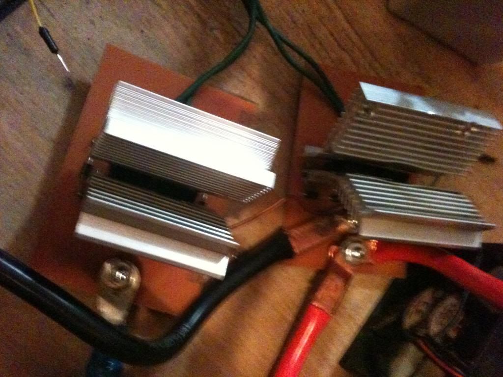
          I am this morning, running the Imperial on 24 volts. She is smooth and vary COOL. If I touch the fet mounting bolt, I can just tell it is not the temp. of room, maybe 2 or 3 degrees higher. On 24 volts she seems to run best at about 900Hz while at 50%. Now we are getting a much louder motor sound and the table is starting to vibrate. I will now go to 36 volts and check her out. This is cool because at 24 volts, no need for fan yet. I used the large heat sinks from four power supplies and put one on each side of fets for both fet units. I will show this later today.
          Dana
          "Today's scientist have substituted mathematics for experiments and they wander off through equation after equation and eventually build a structure which has no relation to reality."
          Nikola Tesla

          Comment


          • I knew You could "easily" make it happen

            Originally posted by prochiro View Post
            I am this morning, running the Imperial on 24 volts. She is smooth and vary COOL. If I touch the fet mounting bolt, I can just tell it is not the temp. of room, maybe 2 or 3 degrees higher. On 24 volts she seems to run best at about 900Hz while at 50%. Now we are getting a much louder motor sound and the table is starting to vibrate. I will now go to 36 volts and check her out. This is cool because at 24 volts, no need for fan yet. I used the large heat sinks from four power supplies and put one on each side of fets for both fet units. I will show this later today.
            Dana
            Hello there Dana!

            Grrrreat!...I am very glad you went for it! ...I always knew you could do it my friend...and all the way and very sophisticated with Sir J.S Monster Pulser...awesome!

            Now, talk to me, lol, I know you are very excited on your first runs...so, please best way to go is to calm down...

            So, now tell me...

            Are you pulsing all four channels as per 1,2,3 and 4...with dead times in between?...or just two Inputs?...tell me, tell me!...lol

            Make tests as adding a mechanical load to shaft and watch amps behavior..

            At video, please show Motor Volts/Amps Input as RPM's...

            Remember we are hitting for a range between 3200 to 3800 RPM's only (where 3600 is the ideal speed) ...so,you do not need to climb much higher IF Motor is taking load easy without rising amperage...and speed remains steady.

            Measure Hertz at those RPM's...it will tell Us the range to reach and maintain steady at.

            See if Arduino through the PC Interface is able to print a square wave spec's at those precise parameters of all channels, it would be wonderful...

            You are doing a heck of a job my friend!!...Congratulations!


            Warm regards and


            Ufopolitics


            P.D: I am working on a Second External Connection...where amperage would drop down so low...that only seen it could believe it...
            Principles for the Development of a Complete Mind: Study the science of art. Study the art of science. Develop your senses- especially learn how to see. Realize that everything connects to everything else.― Leonardo da Vinci

            Comment


            • Resonance!

              Originally posted by warrensk View Post
              Hello all,

              Something ive noticed with my motor so far is when it hits a certain speed with a pulsed input frequency and a cap bank on the output in series....the cap bank will charge up higher than the input voltage and start going even faster. During this phenomenon my amp reading goes nuts and goes to NEGATIVE 5 amps in some cases....Not sure if this is actually right....so I will be doing further testing. Ive had the cap bank charge up to 21 volts before with a 13.8 volt input in parallel. This only happens again at very specific frequencies and also seems to depend on the speed of the motor as the pulsed input frequency is applied.Very interesting indeed. I kind of think of these motors as rectifiers of electricity, in the sense of "distilling" the hot from the cold....

              Any thoughts on what to do with this "cold" side? I believe it to be the constant emf generated from his generators back in the day that tesla was using for his tesla coils....what happens when a tesla coil is run only off of this kind of electricity? I think this is where things may be getting weird and why no one has been able to replicate some of the things tesla described. We currently use AC in tesla coils....which can generate the same resonant properties but pulsed DC COLD electricity would do some rather more interesting things i think...
              warrensk
              BINGO.

              I have been totally mesmerized by Ufo pulsing his motor and it holds the same amperage when loaded down, just bc of the pulsing. I am not a good study of the my-motors thread on capturing radiant energy from a coil but did not catch the mention of resonance there yet. But when dealing with anything coils, one must put on his resonance hat. I mean really, folks, N. Tesla didn't seem to make a move unless it had something to do with resonance. So Warren, you should look at your circuit as a tank LC circuit and figure out the textbook resonant freq. Then if it is a 4 stator/4 brush pair motor, you are pulsing it twice per rpm. I actually think the pulsing should be timed with the rpm and the resonant frequency of the motor LC circuit, one pulse in on the motor commutator, harvest the energy out on the Generator brush, round and round she goes. For an Imperial motor turning the Mecce Alte at 3200-3600 rpm, with an optimal rpm in there somewhere, maybe a coil-pair circuit should be tuned with additional coils/cpacitors such that its resonant freq would be that rpm (times 2 don't forget), or some multiple or harmonic???

              I distinctly remember someone who used to run big mowing machines saying that is how they cut grass, got a machine running at a tuned rpm to get the most power, saying he wanted to do that with his project, I think it was Cornboy... Well I highly suspect that this is another piece of the puzzle. With Ufo pulsing his Imperial and putting a huge load on it without increasing amps, just envision this running in resonance. I mean really, this could be like a runaway nuclear reaction... Or at least opening the fire hydrant of cold electricity... Or am I the last guy here to understand this...
              Off hand here is what I would do; run it through a capacitor bank or self charge your battery, also hook up an asymm generator, run the excess through a grid tie inverter and run you electric meter backwards? Just a thought

              Warren, hats off to you

              Edit: Actually I think the relationship between tuned rpm and resonant frequency would be

              Rfreq=Trpm x #commutator segments x #Brush sets

              where 1 brush set is motor generator pair, and the commutator segment should never be pulsed at a faster rate than one pulse per segment or else that throws you into CEMF situation. I think ideally the pulsing should be tied to the rpm at all times so that each commutator gets one pulse of the desired duty cycle at all times
              IMHO

              So you figure out the basic electric properties of a motor coil pair to get its resonant freq. then solve for the tuned rpm to run the motor at?
              Last edited by sampojo; 03-29-2013, 04:15 AM.
              Up, Up and Away

              Comment


              • Originally posted by Donald Haas View Post
                Yea, you got it near to perfect! If you rotate the motor to be vertical with brushes it is 100% perfect.
                There are about 4 simple rules to obey. Schematics can be red easily if :
                • Battery (or power terminals) sit left with plus lead up
                • +line top / GND line bottom
                • Main current in the circuit flows perpendicularly from top to bottom
                • Control lines will prefer to run from left to right (except feedbacks like at opamp).

                You perform great learning steps!
                JS
                Experts spend hours a day in order to question their doing while others stopped thinking feeling they were professionals.

                Comment


                • Resonance & more

                  Do not confuse OU to be result of one single parameter only.

                  First of all you have to admit that any coil (including motor coils) being pulsed (by monster driver or by commutator) will oscillate as tank circuit because it owns a - so called - parasitic interwinding capacitance. Besides: That is partly true but there is more to it. Interwinding capacitance entered in the formula does not explain real frequency measured.
                  Resonsnce frequency is being hit at switch on and switch off. Imagine a highly felxible wand being thrown from one person to another and back again. At flight time it will oscillate with its own resonance frequency. Swinging stops if catched and will start instantly from new.
                  Did anybody measure by scope the resonance frequency of motor coil while pulsed i.e. 10% duty cycle (motor does not need to turn but pole needs to be adjusted to its drive sector). This frequency might be quite high.
                  If we know the other effects and their frequencies we could try to adjust coil frequency with small caps. But who knows where to adjust to?

                  This genuine coil frequency interacts with other frequencies / phases. Depening on value they might foster or counteract each other. Imagine pulsing frequency, motor speed vs. commutator switching, regard temperature influence .....

                  Ferrous cores (and magnets) own several genuine resonance freqencies extreme high Q / small band width (MHz range). If any frequency in the setup hits a subharmonic SHE will surface and check the event. Any core of very same make owns other resonances. Very difficult to hit them!

                  An additional effect is the phase shift between current and voltage while resonating along those special cases of current and voltage node. She swings laying in the hammock of reactive power and wonders on why humans do not dare to hook her hammock to their machines. (Consult my recent post regarding reactive power)

                  One invaluable feature of UFO motors is that traveling coils live in clearly separated realms (drive time vs. relaxation time) - very unique construction! Hence effects mentioned above can be studied for their contribution. In the end it might be esential to adjust generator brushes individually (I remeber UFO mentioned it some time ago)

                  Imagine you know the genuine resonance frequncy of your motor coils and you pulse your motor with a harmonic of it!!!!!! You might hit a sweet spot.
                  You might hit another one if those both frequency hit the commutator switching freqency (related to rpm) .........
                  And imagine you are able to hit subharmonic of ferrous resonance

                  Now comprehend those effects above as a bed of flowers. We need to find out what flowers we have to pick exactly and when in order to have a neat gift for HER. We might be allowed to omit some of them but we surely need pick more than one.

                  I want you to be aware of your wide playground in order to be alert to any chance passing in order to catch it.

                  I ask you kindly to not feel discuraged. Proceed building your motors and pulsers. They are your basic tools for gardening your beds of flowers.
                  JS
                  Last edited by JohnStone; 03-28-2013, 08:09 PM.
                  Experts spend hours a day in order to question their doing while others stopped thinking feeling they were professionals.

                  Comment


                  • Imperial running

                    Hello UFO, JS and All

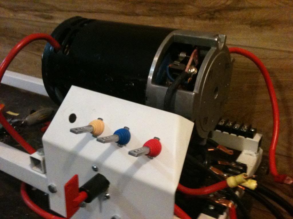
                    I have the Imperial running on P1 and P15 with the rest just hanging loose.


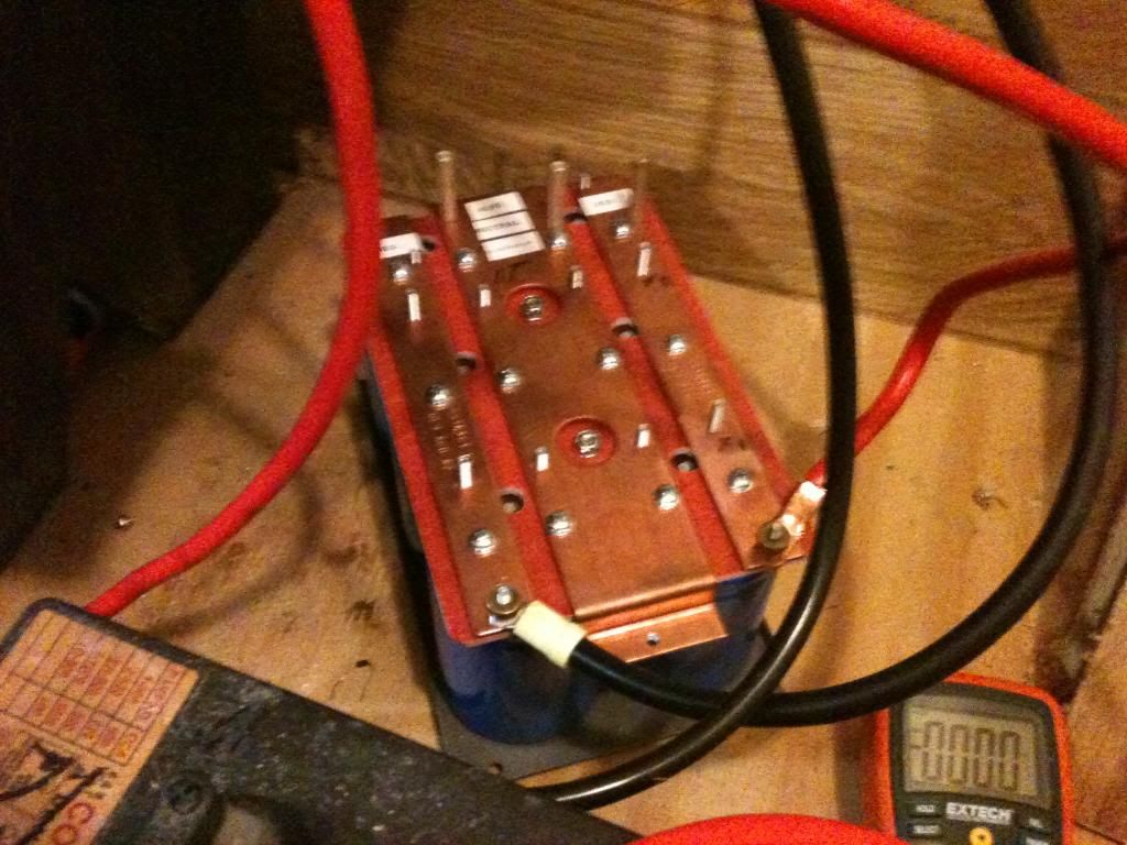
                    This is the cap bank


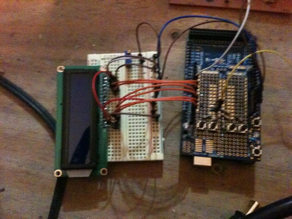
                    Arduino and LCD

                    Monster Board


                    Fet board and heat sinks


                    This video is a non running explanation of the system so far.
                    PWMImperialfilm 001 - YouTube


                    This video is Imperial running at various speeds up to 2000RPM with P1 and P15 only under 36 volts.
                    IMG_0147[1] - YouTube

                    @UFO
                    Just hold on and let me get my wits. I will maybe get amps at various configurations tonight. Should I also hook up the other two lines so it will be running on all four. If so, how do you want it wired. I think the fets can take anything now. Also remember that the 2000 RPM is only with two power lines. Measurements at this point without the total setup will not be totally helpful.

                    @JohnStone
                    The Arduino pauses once in a while when changing parameters and I do not know why exactly. It may be that as I am powering it with computer voltage at a distance, voltage may be low and needs a conversion to a six volt battery?

                    Dana
                    "Today's scientist have substituted mathematics for experiments and they wander off through equation after equation and eventually build a structure which has no relation to reality."
                    Nikola Tesla

                    Comment


                    • Magnetism

                      Another detail:
                      Do not believe in those magnetic field lines your teacher demonstrated long ago at school with iron filings!. In fact you saw a section out of a double torus. It was in front of you and nobody realized it!.
                      - Harmein Nassim shows it (youtube)
                      - Remeber Howard Johnson The Secret World of Magents
                      - And here you have additional scinteific proof. MUST WATCH
                      • Ball shaped magnetic fields
                      • Magnets repelling non magnetic balls.
                      • Attraction and repelling at same time like molecules in crystals or atom nuclei.
                      • N and S do not necessarly attract (reversed magnetic coupling).


                      Be aware that we do not deal with simple magentic lines. This notion performs on the level of my cat being convinced that the ultimate source of food is a magic can which I open from time to time.
                      Magnetism performs as vortices in a double torus shape. Now imagine those shapes being active in real motors like we build today. And imagine what we can do with this knowledge. Be aware we do not build some toys here but scientific instruments.
                      JS
                      Experts spend hours a day in order to question their doing while others stopped thinking feeling they were professionals.

                      Comment


                      • Imperial update

                        The max Amps with P1 and P15 running the motor, 36 volts,100% duty cycle and 1000 Hz is 20 Amps. Not a bit more at any time. This was taken on the battery positive line with a shunt and 100 amp analog meter. I think that JohnStones Monster calculations were right on. I do see a lot of commutator sparking yet but that may be because of partial system not hooked up. I also forgot to mention that if the wires from the capacitor attached from positive to neg are only of 12 Gage stranded, look out, they will glow red and stink up the house.
                        Dana
                        "Today's scientist have substituted mathematics for experiments and they wander off through equation after equation and eventually build a structure which has no relation to reality."
                        Nikola Tesla

                        Comment


                        • What about the HEAT?

                          @Bro Donald
                          OK, I agree that commutator heat must now be contained. Sparks+heat. What has your bedini like circuit done so far (if you have tested it yet). It looks interesting and we all can see that it will charge a battery, but what about the heat. Is there a visual reduction of sparking? If there is, this could be the biggest Imperial motor first birthday party ever...
                          "Today's scientist have substituted mathematics for experiments and they wander off through equation after equation and eventually build a structure which has no relation to reality."
                          Nikola Tesla

                          Comment


                          • Originally posted by prochiro View Post
                            Hello UFO, JS and All

                            I have the Imperial running on P1 and P15 with the rest just hanging loose.

                            This video is a non running explanation of the system so far.
                            PWMImperialfilm 001 - YouTube


                            This video is Imperial running at various speeds up to 2000RPM with P1 and P15 only under 36 volts.
                            IMG_0147[1] - YouTube

                            @UFO
                            Just hold on and let me get my wits. I will maybe get amps at various configurations tonight. Should I also hook up the other two lines so it will be running on all four. If so, how do you want it wired. I think the fets can take anything now. Also remember that the 2000 RPM is only with two power lines. Measurements at this point without the total setup will not be totally helpful.

                            @JohnStone
                            The Arduino pauses once in a while when changing parameters and I do not know why exactly. It may be that as I am powering it with computer voltage at a distance, voltage may be low and needs a conversion to a six volt battery?

                            Dana


                            Hello Dana!

                            First of all, I am very proud of having You here, my friend!
                            You and Machine Alive have been working very hard on Imperial/Mecc Alte, besides spending quite some investment into all this Research and Development...that deserves a great recognition as compliments from ALL of Us, and We all should be very grateful to have hard workers like you here.

                            Nice and SWEET pulsing you've got going on there my friend!!...Finally it is proven that the Monster Pulser works fantastic...it finally "tamed" Imperial!!
                            The hardest part of pulsing Imperial is exactly at the starting and low speed pulsing like you just did on the last video...

                            This Asymmetric Machines, once they start, they pull quite some high amperage, till they reach the Higher and normal operating speed, then coils tend to balance themselves and start drawing much less Amperage...Must of Pulser/FET failure, occurs at Start and low speed pulsing operation ...and ,again, You already did that hardest end part, perfectly fine!.

                            I wanna tell you that the Motor runs very sweet , strong and very smooth, I see quite some of blue-purple arcing/sparks, and as you wrote...IF You only had 20 Amps there...then definitively it is HER...coming at the commutator surface. I HIGHLY recommend to keep checking also the Temp. with an IR Thermometer at commutator and brushes!!

                            If it is HER...give her "other things to do"... ...deviate HER from your Input flow with Diodes (remember First Thread right?)..Load Your Output Gates with some CFL's...whatever...get The Lady to Illuminate Your Video Scenery ...or with a Coil like Bro D mentioned...

                            Then going over the Electronics and your set up:

                            You have one Monster Pulser connected to Arduino Processor...and you are pulsing parallel P1-P15 using same Monster Module with Two FET's (I know each Module have Two FET's...) ..FET's are parallel, same Drain to both Motor Input Gates...am I right so far?

                            If it is so...then Monster Pulser can definitively do this job EASY...I mean...piece of cake brother!...cause you are pulsing two Input Gates with only one Module...it was meant One Module per Input Gate.

                            If You would have at least Two Monster Pulser Modules...then you could pulse both Inputs (P1-P15) separate, BUT, with a pretty good Dead Time between square waves, where P-15 would ALWAYS be ahead of P1...Arduino could do that as also vary and play with that Dead Time...that is where the "key" is, my friend...then you will see a huge speed increase when DT shortens (Dead Time) (Let's call it like that in short letters from Now)

                            Actually, once we get the desired speed range by modulating the Main Parameters (Frequency/Duty Cycle)...then DT could be used just to "jump up" Machine when Mecc Alte is Loaded...this way, the Input current/voltage/frequency/duty cycle would not have to be even touched.

                            Do You understand what we are going to be doing here right?...We are playing by getting closer the Input Pulses from P1-P15...HOWEVER, We MUST FIRST make sure that at the way you are pulsing it now(both at ZERO DT)...We reach the Peak RPM's (3800 at least)

                            Now, in your latest post...you wrote:

                            The max Amps with P1 and P15 running the motor, 36 volts,100% duty cycle and 1000 Hz is 20 Amps. Not a bit more at any time. This was taken on the battery positive line with a shunt and 100 amp analog meter. I think that JohnStones Monster calculations were right on. I do see a lot of commutator sparking yet but that may be because of partial system not hooked up.
                            What was your RPM there?...we need that Parameter Bad!...actually it is one of our main Target so far...We all know Torque is there to turn Mecc Alte easily UNDER LOAD...like I have shown on Videos...the main problem here are due to just two parameters...High Amp Draw and Speed drop.

                            You must realize that just by mechanically attaching Imperial to Mecc Alte, even without a Load hook to Gen Head...it WILL Raise Input Amps as it will decrease RPM's... because of Generator Stator/Armature drag plus friction losses from shaft connectors....This part is VERY IMPORTANT to keep it in mind!


                            Excellent work my friend!, You are now in the Front Driving Seat of this Ship to the Future...


                            Warm regards and


                            I will keep going over with you...but I need to know if what I wrote/you have is correct.


                            Ufopolitics
                            Principles for the Development of a Complete Mind: Study the science of art. Study the art of science. Develop your senses- especially learn how to see. Realize that everything connects to everything else.― Leonardo da Vinci

                            Comment


                            • @UFO
                              It will take a few re-readings for me to understand your last post but, one question you asked was about RPM at 100% duty and 1000 HZ, that was 2000 even.
                              What the pulser is doing is hitting P1 and P15 at the exact same time but if I understand you right, we may want an offset in the timing that can be controlled between P1 and P15, is that correct.?
                              Dana
                              "Today's scientist have substituted mathematics for experiments and they wander off through equation after equation and eventually build a structure which has no relation to reality."
                              Nikola Tesla

                              Comment


                              • Ok, I will not expand that much now...

                                Originally posted by prochiro View Post
                                @UFO
                                It will take a few re-readings for me to understand your last post but,
                                Ok, promise I will not expand that much now......Plus I will not use any Spanglish from Sampojo...

                                one question you asked was about RPM at 100% duty and 1000 HZ, that was 2000 even.
                                Ok, got it...could it go up higher, within the required range?

                                What about rising voltage?...another battery...I believe the Monster Pulser could go up to 48 Volts right?...adding another battery is not going to affect amperage.

                                What the pulser is doing is hitting P1 and P15 at the exact same time but if I understand you right, we may want an offset in the timing that can be controlled between P1 and P15, is that correct.?
                                Dana
                                Yes, that is correct!! that is the "Perfect way" to express it in the English Language...

                                See, when we pulse both Input gates at same timing...the Pairs "ahead" in rotation (in this case P15) are receiving the pulse delayed...is like Firing two cylinders in a Gas Engine at same exact time...it NEVER happens...there is ALWAYS a firing order based on angles ofthe whole 360 º...there could be two cylinders at same time at TDC...BUT ALWAYS...One is at Compression while the other is at exhaust stage.

                                On Asymmetrical Machines, the "firing order" should also follow a sequence, delayed by a Dead Time between pulses. Realize that when we energize JUST a section of the Rotor Mass...that volume area receive an "uneven/asymmetrical" push-pull related to the other non energized side, impulsing it faster than the rest of the rotor mass (tangential acceleration forces).

                                Hope you understood now in one read...lol

                                Regards

                                Ufopolitics
                                Principles for the Development of a Complete Mind: Study the science of art. Study the art of science. Develop your senses- especially learn how to see. Realize that everything connects to everything else.― Leonardo da Vinci

                                Comment

                                Working...
                                X