Announcement

Collapse
No announcement yet.

My Asymmetric Electrodynamic Machines

Collapse
X
 
  • Filter
  • Time
  • Show
Clear All
new posts

  • grounded
    replied
    Originally posted by Ufopolitics View Post
    Grounded,

    Whenever you wind a coil around any piece of ferromagnetic core and run electricity through the wires, the iron core WITHIN COIL magnetizes in a polarization defined according to the way you wound it...or the way you inject the voltage polarity.

    When the case of Motors...the Rotor Poles and Overlapped Coils...We turn them on one by one, so only the segment of core comprehended within the energized coil (in sequential turn) would be magnetized...

    In reality...if we could be able to just see the magnetic fields interacting in each turning Asymmetric Rotor...we would observe an almost STEADY magnetic field Pulsating in the firing designated timing angle related to Stators...while the iron core and coils keeps spinning, no matter the speed, and...the faster the spinning...the faster the pulses to the point it would show almost a steady Field...picture all this in your mind...if you could...

    Hope this helps...

    Ufopolitics
    yeah, perfect. thanks ufo.

    i thought it might be like this, charging the steel, but i wasnt sure, as my knowledge on electronic components is next to nothing.

    i can see why you wind like you do now, for maximum surface area, and a full, even pulse, across the section of poles.

    good stuff

    edit : have you tried wrapping a chain of several single poles before ?
    so that the single segments get a concentrated blast of magnetism ? (if it works like that)
    Last edited by grounded; 05-10-2015, 01:41 PM.

    Leave a comment:


  • Ufopolitics
    replied
    Originally posted by HuntingRoss View Post
    Hi UFO

    I have been certain about this fact since this argument was fabricated by a certain participant on this thread.

    The two diagrams posted illustrate that certain participant knows 'DICK' about timing, and by calling the 12 pole '4 pole pairs' incorrect implied it was correctable. IT IS NOT correctable.

    You and I were seeking 'final agreement' and I conclude from your comments now, that we agree on the only outstanding issue...being, the angle for P2 to clear the brush MUST be included in the correct timing design for all motors.

    With regards to the 'failure to perform of [my] previous model testing'... I can confirm that none of those failures were due to the issue identified as inherent in the 12 pole '4 pole pairs' geometry.

    I have already (previously) agreed that 'lapping pairs' was the only salvation for the inherent flaw and, yes, I have built both 4 and 5 pole lapping pairs and they were not adequate to surpass the OEM.

    I have subsequently returned to and pressed ahead with 'lapping groups' as I have found them to be superior in every way.

    Testing results for my latest motors will be suppressed until fully completed.

    All I will add to this is my motor tests are now within 5% efficiency of the OEM motor which removes any criticism regarding my build quality and motor timing. The basis for comparison of test results is courtesy of Prochiro's horsepower and efficiency software which is an excellent piece of 'kit'.

    As a spoiler for future announcement...results indicate near parity on torque with much increased rpm against a falling (almost tolerable) power consumption compared to the OEM.

    Good Hunting

    mark
    Great to know your advances there Mark!

    Hope those 'Lapped Groups' are not referring to the single commutator structure...but to the fully Dual Comm Asymmetric Model...

    Hope to see those 'suppressed tests' released very soon!


    Take care


    Ufopolitics

    Leave a comment:


  • HuntingRoss
    replied
    Originally posted by Ufopolitics View Post
    Ok, Mark,

    Now that you are so sure about the Four Pole Coils in the Pair NOT working good because of BAD timing...and after affirming it with my previous quoted text...

    Then I believe that by now you would realize why...the failure to perform of your previous model testing versus the OEM?

    The 'solution' was to overlap Coils in the Pair, like I wrote above...

    So, did you already built that new Overlapped version and test it?

    Would like to know the results...so we could all put this "page" behind...


    Regards


    Ufopolitics
    Hi UFO

    I have been certain about this fact since this argument was fabricated by a certain participant on this thread.

    The two diagrams posted illustrate that certain participant knows 'DICK' about timing, and by calling the 12 pole '4 pole pairs' incorrect implied it was correctable. IT IS NOT correctable.

    You and I were seeking 'final agreement' and I conclude from your comments now, that we agree on the only outstanding issue...being, the angle for P2 to clear the brush MUST be included in the correct timing design for all motors.

    With regards to the 'failure to perform of [my] previous model testing'... I can confirm that none of those failures were due to the issue identified as inherent in the 12 pole '4 pole pairs' geometry.

    I have already (previously) agreed that 'lapping pairs' was the only salvation for the inherent flaw and, yes, I have built both 4 and 5 pole lapping pairs and they were not adequate to surpass the OEM.

    I have subsequently returned to and pressed ahead with 'lapping groups' as I have found them to be superior in every way.

    Testing results for my latest motors will be suppressed until fully completed.

    All I will add to this is my motor tests are now within 5% efficiency of the OEM motor which removes any criticism regarding my build quality and motor timing. The basis for comparison of test results is courtesy of Prochiro's horsepower and efficiency software which is an excellent piece of 'kit'.

    As a spoiler for future announcement...results indicate near parity on torque with much increased rpm against a falling (almost tolerable) power consumption compared to the OEM.

    Good Hunting

    mark

    Leave a comment:


  • Ufopolitics
    replied
    Simple old principle...

    Originally posted by grounded View Post
    question to anyone that knows -

    how do the various poles, of the steel armature, interact with a single winding ?

    does the contacting wire physically inject the metal with magnetism ? or does the coil just pulse by itself, and the amature does nothing ?
    Grounded,

    Whenever you wind a coil around any piece of ferromagnetic core and run electricity through the wires, the iron core WITHIN COIL magnetizes in a polarization defined according to the way you wound it...or the way you inject the voltage polarity.

    When the case of Motors...the Rotor Poles and Overlapped Coils...We turn them on one by one, so only the segment of core comprehended within the energized coil (in sequential turn) would be magnetized...

    In reality...if we could be able to just see the magnetic fields interacting in each turning Asymmetric Rotor...we would observe an almost STEADY magnetic field Pulsating in the firing designated timing angle related to Stators...while the iron core and coils keeps spinning, no matter the speed, and...the faster the spinning...the faster the pulses to the point it would show almost a steady Field...picture all this in your mind...if you could...

    Hope this helps...


    Ufopolitics
    Last edited by Ufopolitics; 05-09-2015, 04:23 PM.

    Leave a comment:


  • Ufopolitics
    replied
    Originally posted by JC4me View Post
    Hello UFO and Machine Alive,

    GoferParts.com is the distributor Imperial made me use for UFO Kit. Dyann did not respond, maybe because Gofer as their distributor is new. The 2012 UFO Kit prices have changed, or middle-man jacked-up, from $268 US to $445 US with 10-weeks lead time. July 15th delivery date.
    Hello JC4me,

    Oh man, I really hate when they do something like that!!...I am pretty sure some "good business man" had this "bright idea" to buy out this parts and re-sell them(with huge profit$ of course) ...taking it away from Imperial.

    That is a Jack up 'profit' of almost double from original price!!

    Factory motor new price, and itemized UFO Kit Parts line-items new prices coming tomorrow. I asked Nicky at Gofer for this today after weeping on the phone about the UFO Kit price Jolt. Friday i will call and get it in e-mail for the others who will follow your advice. Am I the only one to buy one since 2012?

    When i see how hard it looks to unwind, i surrender and painfully accept your advice to build this UFO Kit as "Easiest".
    Yes, I see...however, Dyann has given the MSRP or "List Price" for every single Item on this Kit...directly from the manufacturers (Imperial)...so, honestly...I would Insist on getting the same deal, or at least a 10-20% increase as Max...on top of established MSRP.

    Some of this parts like the Commutators are made in China...so, imagine the price they pay there for each when buying wholesale.

    This is a BIG motor. Along with this huge Imperial, I am wanting to learn about the 6KV generator for this thing you mentioned, to turn Bedini SG battery power back to usable AC, so i can put it to work.

    I will be reading until July 15th, and buying 5 LBS 16 AWG 200C Magnet wire. If you can, please post or PM small hardware details, like the woven insulator pasta, Stave-Sticks to hold windings in, Brush Cables, ("6 AWG", but are they 6 AWG 'Fine-Stranded Silicone Hobby Wire'?

    Thank you for your help

    -Ward

    Wow, stop there!
    ...a 16 awg was the OEM wire...but NOT GOOD for Asymmetric Winding!

    18 awg would be the right gauge friend...or finer than.


    Regards


    Ufopolitics

    Leave a comment:


  • grounded
    replied
    question to anyone that knows -

    how do the various poles, of the steel armature, interact with a single winding ?

    does the contacting wire physically inject the metal with magnetism ? or does the coil just pulse by itself, and the amature does nothing ?

    Leave a comment:


  • Ufopolitics
    replied
    Originally posted by HuntingRoss View Post
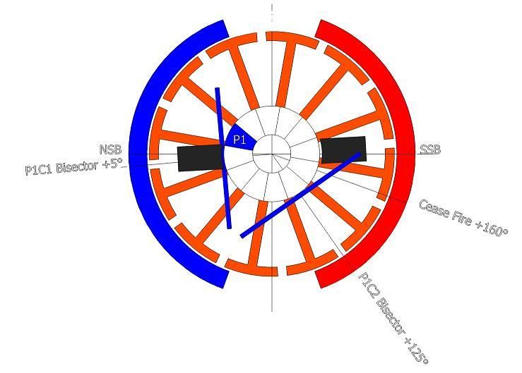
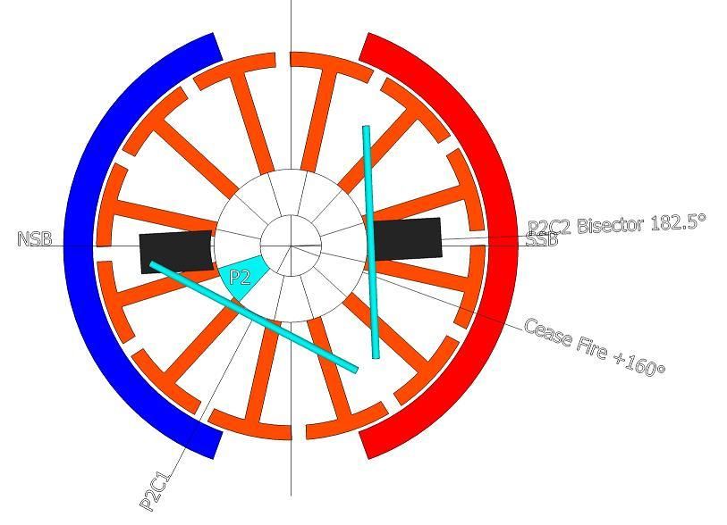
    The following images answer the ON/OFF timing angles for the 12 pole rotor wound as 4 pole pairs.

    [IMG][/IMG]

    Image 1 indicates P1 on the brush by 1° with the P1C1 coil 5° past the NSB. This is the 'ON' timing angle.

    [IMG][/IMG]

    Image 2 indicates the point at which P2 disconnects from the brush shown exactly at 0° disconnection. This is the 'OFF' timing angle.

    This places the P2C2 bisector at 2.5° past the SSB and 22.5° past the ideal 'cease fire' angle.

    Originally Posted by Ufopolitics View Post
    NOW, IF WE DO NOT FULLY DISCONNECT P2 & P16 BEFORE IT REACHES SOUTH STATOR BISECTOR...WE MUST DISREGARD THIS METHOD AND SWITCH BACK TO PREVIOUS OVERLAPPED METHOD, WHICH OFFERS MORE ADJUSTMENTS.
    The quote is for the 28 pole Imperial motor. For the purpose of the 12 pole motor, reference to P16 is irrelevant.

    The only conclusion to be drawn is...P2 DOES NOT disconnect until AFTER the SSB and therefore the 12 pole rotor 4 pole pairs CAN NOT be correctly timed.

    Hunting

    mark
    Ok, Mark,

    Now that you are so sure about the Four Pole Coils in the Pair NOT working good because of BAD timing...and after affirming it with my previous quoted text...

    Then I believe that by now you would realize why...the failure to perform of your previous model testing versus the OEM?

    The 'solution' was to overlap Coils in the Pair, like I wrote above...

    So, did you already built that new Overlapped version and test it?

    Would like to know the results...so we could all put this "page" behind...


    Regards


    Ufopolitics

    Leave a comment:


  • Ufopolitics
    replied
    Four Stator Ten Pole Rotor...

    Originally posted by sampojo View Post
    I will be trying to get that about bringing bisectors closer. By "from two groups or pairs", you had defined a single group coil as having the pieces or sub-coils for your unipolar windings. So I am assuming you mean one coil group here and the two sub-coils as in the quad unipolar 10-pole diagram I used, is what you mean as in the "pair" of sub-coils? You were spreading a coil group into even more than just a pair of subcoils but I guess those are considered undesirable now...
    Hey Sam,

    First You have there a "Unique" design...a Four (4) Stator and a Ten (10) Pole Rotor...no such a design in our 'marketplace'...
    Normally a Four Stator Symmetric Machine would start at Sixteen (16) to Twenty (20) Poles and up...So, You have a very 'Narrow Margin" to play with expanded Groups or Pairs...reason why I recommended to go Single Coils.


    So it is not the fact of "undesirable" Pairs nor Groups now...but you are trying to reach for the lowest amperage draw or the sweet spot, and I see you have not enough Angle to play towards Attraction without leaving much space at repulse.

    So, even though initially surprised by Garry's magic amp reading, you seem to have grasped a potential explanation here. I believe you are explaining more at Post 7582.
    Yes, exactly the fact that Garry had reached a very ultra low amp draw at very high RPM's...means We could reproduce this "phenomena" at any level within any Asymmetrical Structure Design.

    The "Potential Explanation" I have given before here...it is 'no secret'...it is about adjusting the Firing to occur more towards the South Stator (Attract Mode) than the North (Repulse)

    Now, if you have a very CLOSE Angle between Both Pairs, Groups or even Single Coils Bisectors being fired by two commutator elements contacting both Motor Brushes to the 90º Bisector Angle from two N-S Stators (your case of four stators)...Then, no matter how much you try to fire further away from North...you are very limited before passing with "Leaving" Circuit Bisector the South Stator Center line (Bisector).


    Look at your Settings above...out of the Fixed 90º from Stators Bisectors you have more or less around 85º from Bisector of Repulse Group to Bisector of LEAVING Group at Attract. That is too narrow margin to look for sweet spots.

    Now, getting back at Garry's set up with the Five (5) Pole Radio Shack AN1...He had approximately 144º between both Pairs Bisectors ON, within 180º from the Two Stators Bisectors...which means He had somewhere around 36º to play searching for the sweet spot...or 18º from North and 18º to South Attract in 'Neutral Position'... And as He mentioned before...the best timing occurred more towards attract mode...which could have been 21º away from North...and 15º to attract at South Stator...or somewhere around that combination.

    ¿Comprende?

    I guess I am getting good at building this GM window regulator style motor, except my dual stator double rotor is not tunable and its magnets are clipped to fit in a door.

    Would the tuning for a dual stator and a quad stator be the same for the 10-pole rotor using single coils? Probably a dumb question, NO is the answer I am thinking.

    For the quad stator, would you put the 4-pole single coil in the same location as the overlapped 3-pole pair here?

    You gotta have room to move brushes searching for the sweet spot...or else you are fixed again, even if you narrow the two bisectors with single coils...

    You answered yourself on that question...by putting the SAME 10 pole Rotor from a Two Stator to a Four Stator...you are narrowing the Interaction Angles fro 180º to 90º...

    Since the group winding subtends a total of 4 poles, your 4-pole single coil wind would fit perfect while the 3-pole would shift one pole either way. Any suggestions which way to go for 3? no problemo, probably just go with 4 here for now.
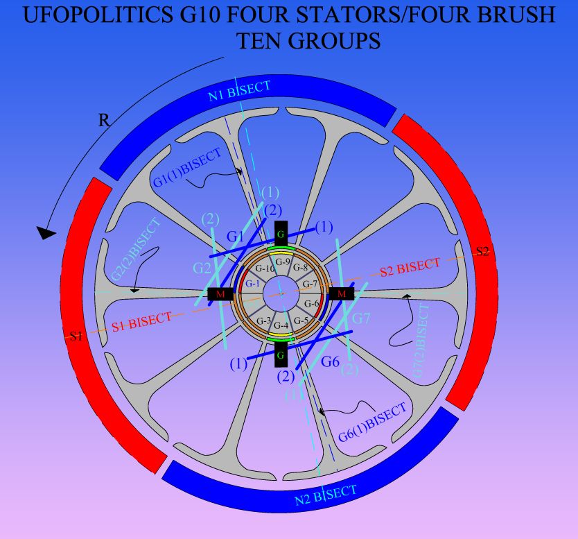
    [IMG][/IMG]

    Note on the Four Pole Coils Diagram above...the Angle between both 'Circuits' being fired, are reduced now from 85º previously to 36º...meaning, you could get further away from North (less repulse) and still not passing the South Stator Bisector...

    Now, the "Perfect Neutral" position for this case would be setting the 36º exactly in the center of 90º angle from stators...right?...and that would be 90-36=54/2=27º...meaning you would start firing exactly 27º away from North of C1 and 27º closer to South Stator Bisector of C2.

    So, firing closer C2 Bisector to the Attract South Stator Bisector, say at 20º...would set your repulse at 34º right?

    Concluding here...I believe your sweet spot should be from that Neutral spot towards closing the gap to the Attract Stator...As I am sure that in higher percentage of attract mode, your motor amps would start dropping real low.

    Is up to you to MARK your LIMIT ANGLE for Attract Mode...once Bisectors starts getting too close...and motor starts slowing down.

    Since my GM dual stator UP-10 is untunable, not worth making it so, I think its time to roll out my 20-pole dual stator Baldor project. Should I go single coil there too? How many poles wide? (8 poles??)

    You had approved a group winding for it at one time. Probably OBE by AN1,2 styles now.

    And is the initial placement of the tuning the same for the single coil RS/GM 5-pole?

    Any "untunable" machine would NOT be a good learning tool my friend...leave those for when we are ready to set a fixed sweet spot...cause we already know how to set it even with our eyes closed...

    Every time you change by expanding or narrowing coils, pairs or groups ...everything must change as far as alignment and timing...

    If I were you, I will try before to work with an adjustable model...a simple one, before moving to Baldor...This Ten Poles and Four Stator could be a great learning tool to find the Gap where that sweet spot is...


    I appreciate your input.

    Sam

    My pleasure friend


    Ufopolitics
    Last edited by Ufopolitics; 05-09-2015, 02:58 PM.

    Leave a comment:


  • Midaztouch
    replied
    Originally posted by JC4me View Post
    Hello UFO and Machine Alive,

    GoferParts.com is the distributor Imperial made me use for UFO Kit. Dyann did not respond, maybe because Gofer as their distributor is new. The 2012 UFO Kit prices have changed, or middle-man jacked-up, from $268 US to $445 US with 10-weeks lead time. July 15th delivery date.

    Factory motor new price, and itemized UFO Kit Parts line-items new prices coming tomorrow. I asked Nicky at Gofer for this today after weeping on the phone about the UFO Kit price Jolt. Friday i will call and get it in e-mail for the others who will follow your advice. Am I the only one to buy one since 2012?

    When i see how hard it looks to unwind, i surrender and painfully accept your advice to build this UFO Kit as "Easiest".

    This is a BIG motor. Along with this huge Imperial, I am wanting to learn about the 6KV generator for this thing you mentioned, to turn Bedini SG battery power back to usable AC, so i can put it to work.

    I will be reading until July 15th, and buying 5 LBS 16 AWG 200C Magnet wire. If you can, please post or PM small hardware details, like the woven insulator pasta, Stave-Sticks to hold windings in, Brush Cables, ("6 AWG", but are they 6 AWG 'Fine-Stranded Silicone Hobby Wire'?

    Thank you for your help

    -Ward
    16awg might not be correct. Your ohms may be too low. Please watch the wind tutorial of the imperial.

    Hint: at the middle of vid #1 is your answer why.

    Keep it Clean and Green
    Midaz
    Last edited by Midaztouch; 05-09-2015, 10:36 AM.

    Leave a comment:


  • Midaztouch
    replied
    Originally posted by sampojo View Post
    Midaz
    Do you think your Imperial can have a sweet spot? Have you tried to find it? Can you imagine a big motor running five or 10 A or less? That would be huge!
    If the motor is built with singular coils and adjustable extra brushes.... The extra brushes on an A1MoGen will find that "Sweet Spot!
    Wow, a magnetic vortex between two magnets that draws energy from the ether!!!

    This would change everything


    Keep it Clean and Green
    Midaz

    if your looking for that "Sweet Spot" I would use the three poles. It's more adjustable... What will be your coil ohm target?
    Last edited by Midaztouch; 05-09-2015, 01:25 PM.

    Leave a comment:


  • sampojo
    replied
    Sweet Spot Quest: AN-2 style winding on GM 10-pole

    Originally posted by Ufopolitics Pg 254 Post 7620 View Post
    @ Sampojo,

    According to your set up ...there is no way to bring any closer both bisectors from two groups or pairs...so, the only possibility you will have there is to go single coils using either Three Poles or Four Poles overlapped.

    You are not seeing any major improvement (magic bullet) because Bisectors are too wide from the two pairs in contact, so there is no gap enough to advance towards more attract nor repulse...like Garry had on his set up.

    So, give it a try to Single Coils, now realize that four poles single coils will have more speed than three poles...but Bisectors would be more spread apart...I believe you could do both and test differences.


    Regards


    Ufopolitics
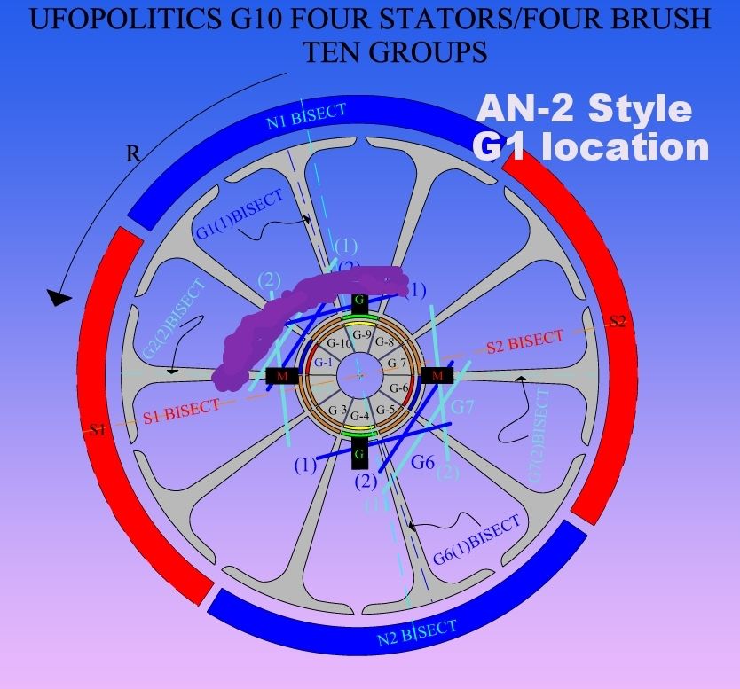
    I will collect some last performance info from my bent-Y Quad Pentium N-S wind, and then tear it down for an AN-2 style. So this is new ground. Question is how to apply the single wind now in a Quad stator embodiment. Here is my stab at it. I am assuming it will have the same orientation as pair coils for the qup-10, and I plan on subtending 4 poles with the single coil(purple).


    I will use identical wire dimensions as my UP-10 pair winding. Multifilar also.

    Ufo, OK to use the same timing angle here???
    Last edited by sampojo; 05-09-2015, 05:19 AM.

    Leave a comment:


  • sampojo
    replied
    Imperial sweet spot?

    Originally posted by Midaztouch View Post
    Since your leaning toward my design, Singular Coils = A1MoGen... Use 4 poles if you want higher RPMs. You will have plenty of room for adjustability & torque will be same as three pole.

    What are you going to use the motor for? If it's just for testing, using 3poles singular coils would be easier to work with.

    Keep it Clean and Green
    Midaz
    Modaz
    Do you think your Imperial can have a sweet spot? Have you tried to find it? Can you imagine a big motor running five or 10 A or less? That would be huge!

    Leave a comment:


  • GChilders
    replied
    Originally posted by Ufopolitics View Post
    Garry,

    Sorry I have missed this post...

    I never meant that I did not believe those Amp readings, I know that the All North could do many "surprises", it is all about an excellent Timing, plus a great, drag free build.

    I just wanted to make sure it was not a typing error, that's all.

    And yes, it is definitively Sci-Fi friend!

    One thing I would like whenever you've got a chance is to give the Spec's of the AN-1 as awg and number of turns per coil in the pair...that's all we need to replicate it...the rest is already posted here.


    Thanks again for your excellent work on this tests, it has cleared a LOT of Black Clouds.


    Regards and wish you feeling excellent !


    Ufopolitics
    Hi UFOPolitics

    When I set up the contest for "The Battle of the Windings" I carefully unwound one of the Goldmine Motors coils. The total length of the wire from the coil was 18' or 550cm of 30AWG wire. I added 3" or 7cm to each end for stripping and tying off the wire. Then my approach was the same one used for the Y wind. In other words I divided the length of 18'6" or 564cm in half and measured that length (9'3" or 282cm) on to another spool after marking that dividing line with a piece of masking tape. Then I measured from the masking tape another 9'3" and cut the wire. I did this for all five coil pairs for the AN1. When I went to wind the coil pairs I took the first three inches or 7cm and used that for stripping and tying off the first commutator and then wound the first coil until I came to the masking tape at the 9'3" or 282cm mark. I did not count the number of windings I simply wound until I came to the mark. Once I got to the mark I removed the tape and continued winding the second coil with the remaining 30AWG wire. Then I stripped and tied off with the last 3" or 7cm of the wire to the opposite commutator and checked continuity before moving on to the next coil pair. Hope that answers your question.

    Cheers

    Garry
    Last edited by GChilders; 05-08-2015, 06:42 PM.

    Leave a comment:


  • JC4me
    replied
    Originally posted by Ufopolitics View Post
    Thanks Ward,

    Below is the only "UFO KIT" available...that I could find...
    ...
    (Edited out image)
    ...
    Just kidding...


    The Info is at page 97 and you could see direct link post below:

    LINK TO UFO KIT

    Now, the "already wound" Rotor is NOT Asymmetrical...so, make sure rotor is NOT wound, however, Dyann knows exactly what this is all about.

    Thanks for your interest in Asymmetrical Machines


    Regards


    Ufopolitics
    Hello UFO and Machine Alive,

    GoferParts.com is the distributor Imperial made me use for UFO Kit. Dyann did not respond, maybe because Gofer as their distributor is new. The 2012 UFO Kit prices have changed, or middle-man jacked-up, from $268 US to $445 US with 10-weeks lead time. July 15th delivery date.

    Factory motor new price, and itemized UFO Kit Parts line-items new prices coming tomorrow. I asked Nicky at Gofer for this today after weeping on the phone about the UFO Kit price Jolt. Friday i will call and get it in e-mail for the others who will follow your advice. Am I the only one to buy one since 2012?

    When i see how hard it looks to unwind, i surrender and painfully accept your advice to build this UFO Kit as "Easiest".

    This is a BIG motor. Along with this huge Imperial, I am wanting to learn about the 6KV generator for this thing you mentioned, to turn Bedini SG battery power back to usable AC, so i can put it to work.

    I will be reading until July 15th, and buying 5 LBS 16 AWG 200C Magnet wire. If you can, please post or PM small hardware details, like the woven insulator pasta, Stave-Sticks to hold windings in, Brush Cables, ("6 AWG", but are they 6 AWG 'Fine-Stranded Silicone Hobby Wire'?

    Thank you for your help

    -Ward

    Leave a comment:


  • Midaztouch
    replied
    Originally posted by grounded View Post
    ok, cheers midaz.
    i think ill re-wind the mini motor, in that case. check out the difference.

    do the same rules with these motors apply for wire thickness ?

    as in - thick wire for rpm, and thin wire for torque ?
    No one has done a thick and thin wire comparison... That I know of with these ALL North motors. Now that I've thought about it, Machinealive, did his imperial North/South wind design with a thicker wire Gauge. His motor was faster!

    Have fun and give it a try. After that, you will be ready for a big motor, for sure!

    Keep it Clean and Green
    Midaz
    Originally posted by Ufopolitics View Post
    Machine Alive used 19 awg gauge, that is thinner than 18 awg.
    Are you sure!? Did you check the posts? I remember that he wanted to use 19 but all he had left to finish a motor was 17awg...


    Midaz
    Grounded,

    Sorry, for the incorrect info. Machinealive used 20.5 wire @ 25turns @ .7ohms per coil... 1.4ohms.

    Got tired of reading through this longgggg thread trying to find the correct info... Had to find & blow the dust of my notebook and there it was, on the 3rd page.

    Keep it Clean and Green
    Midaz

    Ufo, I read through all of my notebook... I wrote a lot of nice stuff about you in there... What happened!?
    Last edited by Midaztouch; 05-09-2015, 09:58 AM.

    Leave a comment:

Working...
X