Announcement

Collapse
No announcement yet.

My Asymmetric Electrodynamic Machines

Collapse
X
 
  • Filter
  • Time
  • Show
Clear All
new posts

  • Midaztouch
    replied
    Originally posted by HuntingRoss View Post
    Not so!

    I built your single coil motor months ago and it remains the most power hungry space heater I have ever built in my short motor career...@ 7.0A @ 5v @ 1795 rpm 'no load'.

    So I'm not surprised at your recent 'test' results indicating huge 'no load' power consumption.

    By way of comparison. The motor I built and prony tested last night, meaning under heavy load, was 6.76A @ 8.97v @ 959 rpm. No load figures, 0.4A @ 10.26v @ 2556 rpm. The motor hardly warmed up during the entire test.

    Happy Hunting


    mark
    UFO said you can post you work here on his thread! Anytime!... Video, wire gauge, resistance, diagram, # of turns, how many poles, ect.... HERE!!!


    You said you made a singular coil motor on my thread 3x! Like I said to you before! How did you build it!? And what would you do to improve it?

    Midaz
    Last edited by Midaztouch; 05-09-2015, 10:22 AM.

    Leave a comment:


  • Midaztouch
    replied
    Originally posted by HuntingRoss View Post
    It's a prophetic story about a traveler that couldn't live by the words that he preached.

    Good Hunting

    mark
    Finally got it!

    Your talking about my surprise visit to a company that would not test the motor.

    Here is what he is talking about. It's from my thread for the A1MoGen.

    Originally posted by Midaztouch View Post


    Don't take No for an answer in an e-mail.

    Today, I loaded up my bicycle and peddled 2 hours to the electric motor company. No appointment, no phone call, no email, no nothing.... just showed up! with the A1MoGen, a 12V battery and jumper cables. Told the secretary I needed my motor checked on the DC power supply, then connected the motor up in the main hallway entrance.... Then got a cup of cold green tea and waited.

    And of course, the head engineer still wanted nothing to do with the A1MoGen but God was on my side. The CEO of Sales came out and was wondering why a motor was spinning in his main lobby...ENTRANCE Front Doors
    He called the engineering department. Their actions said they really didn't want to do it but they ran the A1MoGen on the DC power supply... The head engineer didn't even come to watch.


    The A1MoGen worked fine on a DC Power Supply. After I review the vid, I will put it up soon.

    Keep it Clean and Green
    Midaz "The Negotiator"

    Stopped at the beach to take a picture of the A1MoGen strap on my bicycle for my Adventure documentary.
    Originally posted by Midaztouch April 27th
    Ran my motor on a DC Power Supply today!

    After a long ride with many big bumps and going over many curbs, a wire came loose and got lodged under the magnets. I heard something scraping when I was running the motor in their lobby but I had to play it cool and didn't want touch/adjust the motor. I just let it spin and smiled.

    The engineer staff drag me up 2 long fights of stairs and all the way across the warehouse at top speed! I was carrying the 45lbs A1MoGen. They said 5mins that's it... I was a little upset with their treatment but hey, beggars can't be choosy. Anyway, I only needed 3 mins and the A1MoGen got checked on a DC Power Supply.

    The results from the Vid

    Lowest setting = 1.9volts @ 21amps...40watts starts RPMs(a lot of mechanical drag)
    Highest setting = 20volts @ 21amps

    I had to stop going up in voltage. I heard a loud "PING" in the motor. I thought about, going up in voltage after the loud ping but I decide to live and fight another day ... The "ping" was the wire lodged under the magnet. When I got home, I pull the wire out and it ran smoothly/no scraping... Instead of using all 28 coils, I will have 27 coils, for now...

    Conclusion: The A1MoGen was a success on the DC Power Supply. In my opinion, it's a VIABLE high-performance electric motor!

    Keep it Clean and Green
    Midaz
    Got carried away on the main thread and forgot to post the vid here.

    [VIDEO]https://m.youtube.com/watch?v=xwcPckoSbtA[/VIDEO]

    Big 4 magnet Asymmetric motors/ALL have no problems on the DC power supply, when the timing is correct.

    That was the goal... In my opinion, mission accomplished!

    Keep it Clean and Green
    Midaz

    When the North/South motors were tested, they failed! I had to prove that that these motors are fine...

    Now, everyone can move forward with out any doubts about a DC power supply!

    Mark, I always come correct!!!
    Last edited by Midaztouch; 05-08-2015, 01:27 AM.

    Leave a comment:


  • HuntingRoss
    replied
    Come correct or don't come at all!


    Words to live by as one walks unannounced...after a long ride with many big bumps and going over many curbs, a wire came loose and got lodged under the magnets.
    Originally posted by Midaztouch View Post
    What does this quote mean
    It's a prophetic story about a traveler that couldn't live by the words that he preached.

    Good Hunting

    mark

    Leave a comment:


  • HuntingRoss
    replied
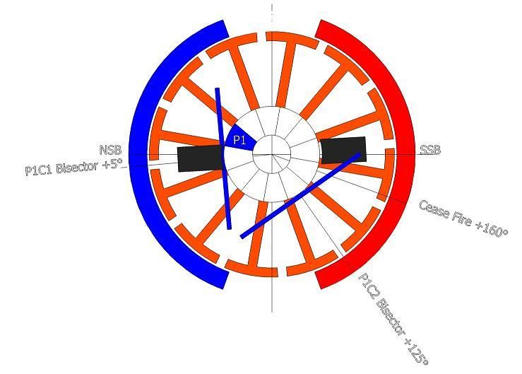
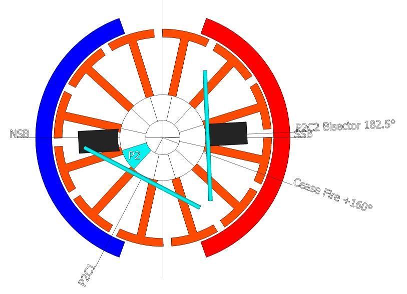
    4 Pole Pairs - ON and OFF angles - 12 Pole Rotor

    The following images answer the ON/OFF timing angles for the 12 pole rotor wound as 4 pole pairs.

    [IMG][/IMG]

    Image 1 indicates P1 on the brush by 1° with the P1C1 coil 5° past the NSB. This is the 'ON' timing angle.

    [IMG][/IMG]

    Image 2 indicates the point at which P2 disconnects from the brush shown exactly at 0° disconnection. This is the 'OFF' timing angle.

    This places the P2C2 bisector at 2.5° past the SSB and 22.5° past the ideal 'cease fire' angle.

    Originally posted by Ufopolitics View Post
    NOW, IF WE DO NOT FULLY DISCONNECT P2 & P16 BEFORE IT REACHES SOUTH STATOR BISECTOR...WE MUST DISREGARD THIS METHOD AND SWITCH BACK TO PREVIOUS OVERLAPPED METHOD, WHICH OFFERS MORE ADJUSTMENTS.
    The quote is for the 28 pole Imperial motor. For the purpose of the 12 pole motor, reference to P16 is irrelevant.

    The only conclusion to be drawn is...P2 DOES NOT disconnect until AFTER the SSB and therefore the 12 pole rotor 4 pole pairs CAN NOT be correctly timed.

    Hunting

    mark

    Leave a comment:


  • Midaztouch
    replied
    Originally posted by HuntingRoss View Post
    Words to live by as one walks unannounced...

    Good Hunting

    mark
    What does this quote mean


    The reason WHY you can't understand these motors is ... After 6mts and the help from me, UFO and other knowledgeable members, you still haven't built one properly yet.

    Mark, on a serious note. Not being sarcastic or rude... Do you have a learning disability?

    If not, I suggest you read ALL of the three threads on asymetric motors and watch as many videos on YouTube as possible on the subject.(repeat 3X) Then come back in 3-6mts.

    Take care & Good luck
    Midaz

    Admitting that you have a problem is the first step toward understanding & recovery.
    Last edited by Midaztouch; 05-07-2015, 09:02 PM.

    Leave a comment:


  • HuntingRoss
    replied
    Originally posted by Midaztouch View Post
    Come correct or don't come at all!
    Words to live by as one walks unannounced...

    Originally posted by Midaztouch View Post
    After a long ride with many big bumps and going over many curbs, a wire came loose and got lodged under the magnets.
    Good Hunting

    mark

    Leave a comment:


  • Midaztouch
    replied
    Originally posted by sampojo View Post
    I will be trying to get that about bringing bisectors closer. By "from two groups or pairs", you had defined a single group coil as having the pieces or sub-coils for your unipolar windings. So I am assuming you mean one coil group here and the two sub-coils as in the quad unipolar 10-pole diagram I used, is what you mean as in the "pair" of sub-coils? You were spreading a coil group into even more than just a pair of subcoils but I guess those are considered undesirable now...


    So, even though initially surprised by Garry's magic amp reading, you seem to have grasped a potential explanation here. I believe you are explaining more at Post 7582.


    I guess I am getting good at building this GM window regulator style motor, except my dual stator double rotor is not tunable and its magnets are clipped to fit in a door.

    Would the tuning for a dual stator and a quad stator be the same for the 10-pole rotor using single coils? Probably a dumb question, NO is the answer I am thinking.

    For the quad stator, would you put the 4-pole single coil in the same location as the overlapped 3-pole pair here?


    Since the group winding subtends a total of 4 poles, your 4-pole single coil wind would fit perfect while the 3-pole would shift one pole either way. Any suggestions which way to go for 3? no problemo, probably just go with 4 here for now.

    Since my GM dual stator UP-10 is untunable, not worth making it so, I think its time to roll out my 20-pole dual stator Baldor project. Should I go single coil there too? How many poles wide? (8 poles??)

    You had approved a group winding for it at one time. Probably OBE by AN1,2 styles now.

    And is the initial placement of the tuning the same for the single coil RS/GM 5-pole?

    I appreciate your input.

    Sam
    Since your leaning toward my design, Singular Coils = A1MoGen... Use 4 poles if you want higher RPMs. You will have plenty of room for adjustability & torque will be same as three pole.

    What are you going to use the motor for? If it's just for testing, using 3poles singular coils would be easier to work with.

    Keep it Clean and Green
    Midaz
    Last edited by Midaztouch; 05-07-2015, 05:18 AM.

    Leave a comment:


  • sampojo
    replied
    Re: Comments on no sweet spot for GM QUP-10

    Originally posted by Ufopolitics Post 7620 View Post
    @ Sampojo,

    According to your set up ...there is no way to bring any closer both bisectors from two groups or pairs...so, the only possibility you will have there is to go single coils using either Three Poles or Four Poles overlapped.
    I will be trying to get that about bringing bisectors closer. By "from two groups or pairs", you had defined a single group coil as having the pieces or sub-coils for your unipolar windings. So I am assuming you mean one coil group here and the two sub-coils as in the quad unipolar 10-pole diagram I used, is what you mean as in the "pair" of sub-coils? You were spreading a coil group into even more than just a pair of subcoils but I guess those are considered undesirable now...

    You are not seeing any major improvement (magic bullet) because Bisectors are too wide from the two pairs in contact, so there is no gap enough to advance towards more attract nor repulse...like Garry had on his set up.
    So, even though initially surprised by Garry's magic amp reading, you seem to have grasped a potential explanation here. I believe you are explaining more at Post 7582.
    So, give it a try to Single Coils, now realize that four poles single coils will have more speed than three poles...but Bisectors would be more spread apart...I believe you could do both and test differences.

    Regards

    Ufopolitics
    I guess I am getting good at building this GM window regulator style motor, except my dual stator double rotor is not tunable and its magnets are clipped to fit in a door.

    Would the tuning for a dual stator and a quad stator be the same for the 10-pole rotor using single coils? Probably a dumb question, NO is the answer I am thinking.

    For the quad stator, would you put the 4-pole single coil in the same location as the overlapped 3-pole pair here?


    Since the group winding subtends a total of 4 poles, your 4-pole single coil wind would fit perfect while the 3-pole would shift one pole either way. Any suggestions which way to go for 3? no problemo, probably just go with 4 here for now.

    Since my GM dual stator UP-10 is untunable, not worth making it so, I think its time to roll out my 20-pole dual stator Baldor project. Should I go single coil there too? How many poles wide? (8 poles??)

    You had approved a group winding for it at one time. Probably OBE by AN1,2 styles now.

    And is the initial placement of the tuning the same for the single coil RS/GM 5-pole?

    I appreciate your input.

    Sam
    Last edited by sampojo; 05-07-2015, 05:01 AM.

    Leave a comment:


  • Ufopolitics
    replied
    Originally posted by GChilders View Post
    @Midaz and UFO
    Those numbers are off of the video I already posted "The Battle of the Windings- The Timing contest". Look it up for yourself. These numbers are off of the clamp ammeter that I used for all of tests. All that I can say is I ran this timing test on both the AN1 and the AN2 numerous times because I couldn't believe it myself. Look up all of the numbers posted in those charts and you will see them as clear as day on the video. Science fiction I suppose it is if you cannot trust the meters but wouldn't that apply to all meters. They simply sample the current. Wow I did not think that you would doubt it. Well if that is the response I get from the people actually involved in this technology I can only imagine what others are thinking. I did not cherry pick the results by the way I ran all of these tests in the same order that they appear. All that I did was cut the middle 10 second section out of each run let the chips fall where they may. Read the numbers off of the meters for yourself. If you wish run the tests yourself, build a model with adjustable timing and see what you come up with yourself. Read em and weep as they say the same set up was used on all of the windings. The same length of copper used on all of them. The only difference is the two commutators for the asymmetric motors, the ability to fine tune the brush position, and the windings themselves.

    Cheers

    Garry
    Garry,

    Sorry I have missed this post...

    I never meant that I did not believe those Amp readings, I know that the All North could do many "surprises", it is all about an excellent Timing, plus a great, drag free build.

    I just wanted to make sure it was not a typing error, that's all.

    And yes, it is definitively Sci-Fi friend!

    One thing I would like whenever you've got a chance is to give the Spec's of the AN-1 as awg and number of turns per coil in the pair...that's all we need to replicate it...the rest is already posted here.


    Thanks again for your excellent work on this tests, it has cleared a LOT of Black Clouds.


    Regards and wish you feeling excellent !


    Ufopolitics
    Last edited by Ufopolitics; 05-06-2015, 11:55 PM.

    Leave a comment:


  • Midaztouch
    replied
    Originally posted by GChilders View Post
    @All
    I contracted some sort of stomach flu on Friday and have been unable to continue they contest. Feeling out of sorts for the last few days I am finally getting back to my experiments.
    Stomach flu... Are you sure you didn't get mentally sick looking for a way to show the magical Sweet Spot of .08 amps

    I spent yesterday afternoon building most of the parts for the load test.I decided to put the Lenz test on the back burner for now until the load test has been concluded. I apologize for the delay.
    I hope you can show that sweep spot consistently or no one will care about your test results with Lenz.


    @Midaz

    I have wasted enough time on you, I will not be answering any of your posts in the future.

    Garry

    You better prove your .08 Or delete it from your result. As it stands, your sweet spot of .08 is in question.

    Keep it Clean and Green
    Midaz

    Come correct or don't come at all!

    Leave a comment:


  • Midaztouch
    replied
    Originally posted by Ufopolitics View Post
    Machine Alive used 19 awg gauge, that is thinner than 18 awg.
    Are you sure!? Did you check the posts? I remember that he wanted to use 19 but all he had left to finish a motor was 17awg...


    Midaz

    Leave a comment:


  • grounded
    replied
    ok, no probs ufo, ill keep the singular coils out of this thread.
    thanks for midaz's thread link.

    Leave a comment:


  • GChilders
    replied
    Load Test delayed due to illness

    @All
    I contracted some sort of stomach flu on Friday and have been unable to continue they contest. Feeling out of sorts for the last few days I am finally getting back to my experiments. I spent yesterday afternoon building most of the parts for the load test. I decided to put the Lenz test on the back burner for now until the load test has been concluded. I apologize for the delay.
    @Sampojo
    I believe that your assumption about the timings is correct. I start in position one with the standard OEM timing. As I explained to UFO this is an unfortunate design on the brush holder as the brushes continue to swing in an arc changing the angle when the rotor is removed. So all of the timing positions from position 1 are relative changes in position from that position. I marked the brush holders with a felt tip sharpie. Then rotated the brush holder the width of the long slot shown in the video for the next mark and marked the second position and then rotated it once more the width of the long slot and marked it with a sharpie for timing position 3. This is a crude method and can be improved upon. Frankly I did not doubt that I would see some performance improvement as I had not tried to time these motors and had more or less ran with the stock timing. The motors worked well and had good rpm and torque even at the stock setting. No one was more surprised than I was at the performance of the new settings. The Load Test that I am about to run should give us a very good indication if this is a valid setting or not. Like I said in an earlier post, this is only the beginning. But it certainly worked amazingly well on this model.
    @Midaz
    I have wasted enough time on you, I will not be answering any of your posts in the future.

    Cheers

    Garry

    Leave a comment:


  • Ufopolitics
    replied
    @ Sampojo,

    According to your set up ...there is no way to bring any closer both bisectors from two groups or pairs...so, the only possibility you will have there is to go single coils using either Three Poles or Four Poles overlapped.

    You are not seeing any major improvement (magic bullet) because Bisectors are too wide from the two pairs in contact, so there is no gap enough to advance towards more attract nor repulse...like Garry had on his set up.

    So, give it a try to Single Coils, now realize that four poles single coils will have more speed than three poles...but Bisectors would be more spread apart...I believe you could do both and test differences.


    Regards


    Ufopolitics

    Leave a comment:


  • Ufopolitics
    replied
    Originally posted by Midaztouch View Post
    No one has done a thick and thin wire comparison... That I know of with these ALL North motors. Now that I've thought about it, Machinealive, did his imperial North/South wind design with a thicker wire Gauge. His motor was faster!

    Have fun and give it a try. After that, you will be ready for a big motor, for sure!

    Keep it Clean and Green
    Midaz
    Machine Alive used 19 awg gauge, that is thinner than 18 awg.

    Leave a comment:

Working...
X