Announcement

Collapse
No announcement yet.

My Asymmetric Electrodynamic Machines

Collapse
X
 
  • Filter
  • Time
  • Show
Clear All
new posts

  • "240 watts was needed to power 400 watt load is not an admirable achievement?"
    Yes, it would, but it's not; that's why i dropped a line to Farmhand, not many have guts to reveal a truth.

    (Cockatoos, you said , you forgotten something amigo, it was me first who pointed you the false approach, and you prove it again and again).

    "I'm very very sorry but you are in grave error on many of those points above"
    Yes, he is, misleading of Tesla's concept.

    "please bring it the the simplest possible level so we can comprehend the total importance"
    It was done from the very beginning; with the SAME motor, wire gauge and length, the original motor working much better. Of course modified one is working too (it still has wire with juice in the magnetic field), but elegance and simplicity of original winding keeps it out of competition so far.
    But who cares, let them play as they want
    They're up to something different now, I even don't want to figure out what it is, since the foundation is rotten.

    And leave me alone, Cockroach , this's an open source, i was not even talking to you.

    Comment


    • Originally posted by boguslaw View Post
      erfinder, ufopolitics

      It's a communication barrier. Maybe that make you feel better if I point that I don't understand both of you So maybe you are talking about the same without understanding each other ? KISS (keep it stupid simple) , please bring it the the simplest possible level so we can comprehend the total importance.
      Coils in existing motors aren't connected correctly...that's it...It's not Lenz or CEMF opposing you its ignorance!

      I have no idea where this thread is going, it is my opinion that none of what has been presented has anything to do with Tesla. Tesla patented one series of machine which I have interpreted as being asymmetrical.....this particular config was in your face, 100% Orthogonal! It is my belief that necessity drove those skilled in the art to find a simpler, more cost effective method for winding machines which was equal in performance to the prior art....the method was found....and the winding of toroids was superseded.

      These are common sense conclusions that I came to, and are subject to the approval to a "competent" authority only.... the waveform generated by the machine I built in my attempt at replicating Tesla's 100% Orthogonal motor is in my opinion.....asymmetrical.

      Hope that was simple enough...now its up to you to find out how to properly connect coils, and configure the magnets in your devices. You have a few options...
      • you can choose to do it like Tesla did it.....(Highly Recommended)
      • you can roll the dice and do it your way....
      • or you can continue down the path you are on and continue to take instruction from UFO, and continue doing what hes instructing you to do...


      When its all said and done, only one of these options will deliver the goods....

      Regards

      Comment


      • Naysayer thread research assistance

        Hey guys maybe due to the extensive size of this thread and the fact That it is made in conjunction with the my motors thread, your research may hav missed the big pic. I just helped a member on the other thread by giving him the point to several key posts and vids in the MyMotors post 2031 P67. Enjoy.

        Edited URL link, was in error 9/12/13
        Last edited by sampojo; 09-13-2013, 03:41 AM.
        Up, Up and Away

        Comment


        • Hello Erfinder, Prompt, and to a lesser extent, Farmhand,---- Jeessuss,---- UFO, takes some time out and you guy's move in, What are you?

          @ Erfinder, i have watched your videos, and i think you have a very valid point or two, but we here would like you to show us how to rewind, or reconnect, the imperial motor to your specifications, so it will use less input under load, and speed up at the same time!!.

          This thread is about practical replication and building, not just theory.

          A simple diagram, or sketch will do, no one here is going to send you an Imperial to modify!

          My interest is purely in Vehicle Traction motors, and they require heavy torque, right from idle, like these motors show.

          @ Prompt, 240watts to get 400Watts, Hmmm!!, i think you will find later on with testing, that what UFO has said, regarding the linear nature, of the progression, as you load this design, will speak quite clearly for itself.

          @ Farmhand, i have followed your posts for the last two years, including the Don Smith thread,( mainly because you are a fellow Aussie) and you have made some very nice Tesla transformers, and achieved some nice results, Please, just because you haven't found over unity in anything you have achieved, Don't let it cloud your judgement, with Negativity, you are a valuable asset, to all here.

          You have said, I will give it, "Three Years", so sit back and watch, and if you can add something that you think may be positive, and help all us,
          " struggling" on this thread, please chime in.


          I mean no Malice, or bad intentions in what i have posted, Let's all work together, towards a common goal.

          Warm Regards Cornboy.

          Comment


          • Originally posted by Cornboy 555 View Post
            @ Erfinder, i have watched your videos, and i think you have a very valid point or two, but we here would like you to show us how to rewind, or reconnect, the imperial motor to your specifications, so it will use less input under load, and speed up at the same time!!.
            I can't show you how to reconfigure an imperial if I don't have one. Unfortunately, you would need to rewind the motors and not just reconnect them....

            Speed up under load is a easy, several individuals one in particular (Tinman) demonstrated how this was done using a motor similar to the ones you are rewinding, but he got the boot...tunnel vision...I really don't get it... I demonstrate acceleration under load using low inductance high low resistance coils operating at low frequency.....no interest.....LOL....

            Originally posted by Cornboy 555 View Post
            This thread is about practical replication and building, not just theory.
            You watched my videos...I am not just theory...I build...I build proof of principle first, cost effective approach...then I modify existing...I don't dive head first into modifying the existing....why....it might surprise you but the system as is might just need a small push in the right direction...but as you have torn it apart completely...you'll never know for sure...

            Originally posted by Cornboy 555 View Post
            A simple diagram, or sketch will do, no one here is going to send you an Imperial to modify!
            No...a simple diagram or sketch will not do....and I know no one is going to send me an Imperial...

            Originally posted by Cornboy 555 View Post
            My interest is purely in Vehicle Traction motors, and they require heavy torque, right from idle, like these motors show.
            OK....just saying you have options....What I am curious about is where you are going to get all that power you will need.....I'm sure you all have that figured out, I'm looking forward to seeing that...

            Regards

            Comment


            • Particulars.

              Hello Erfinder, Tinman, has yet to post a diagram, or Schematic on his experimenting, despite other members of the forum he post's on, asking him to do so, until then, i will just keep trying to replicate, a Wacky, Polyphase, Converter.

              I can't understand, Erfinder, why you can't, sketch, draw, or anything, of what you speak, That dosen't make sense, for someone of your Caliber and electronic experience.

              Erfinder, i am glad you are looking forward to everybody's progress here, please feel free to add anything you think can help our progress.

              OK, if you really, absolutly, need an Imperial motor to show us your way of doing it, send me your adress, and particulars, by PM and i will see what i can do.

              Regards Cornboy.

              Comment


              • Originally posted by Cornboy 555 View Post
                Hello Erfinder, Tinman, has yet to post a diagram, or Schematic on his experimenting, despite other members of the forum he post's on, asking him to do so, until then, i will just keep trying to replicate, a Wacky, Polyphase, Converter.

                I can't understand, Erfinder, why you can't, sketch, draw, or anything, of what you speak, That dosen't make sense, for someone of your Caliber and electronic experience.

                Erfinder, i am glad you are looking forward to everybody's progress here, please feel free to add anything you think can help our progress.

                OK, if you really, absolutly, need an Imperial motor to show us your way of doing it, send me your adress, and particulars, by PM and i will see what i can do.

                Regards Cornboy.
                Check your pm please sir...

                Comment


                • Barriers.

                  Originally posted by erfinder View Post
                  Check your pm please sir...
                  Thanks Erfinder, i don't have Skype, i am not very Computer savy, but surely you can share what you have discovered, here, i mean what's the big deal? Are you worried, that what you have found with rotating devises, is something that shouldn't be shared with all?.

                  Let's break down the barriers here and now!!

                  PS. Please do not call me Sir.

                  Warm Regards, Cornboy.
                  Last edited by Cornboy 555; 07-01-2013, 11:25 AM.

                  Comment


                  • Originally posted by Cornboy 555 View Post
                    Thanks Erfinder, i don't have Skype, i am not very Computer savy, but surely you can share what you have discovered, here, i mean what's the big deal? Are you worried, that what you have found with rotating devises, is something that shouldn't be shared with all?.

                    Let's break down the barriers here and now!!


                    Warm Regards, Cornboy.
                    Skype....that is how it has to work...the information I want to pass on to you if you are interested...didn't originate with me....there is a very short video clip you should see......if you are interested....the offline communication channel is open......its not really proper for me to rebroadcast something that's already out in the open...the problem is the information I am referring to isn't free...we can discuss it offline, I won't post the stuff on an open forum...what you do with what I share with you is your business. Hope you understand..

                    EFTV23...in that video we are instructed how to properly connect coils.....

                    Regards

                    Comment


                    • Ouch.

                      Originally posted by erfinder View Post
                      Skype....that is how it has to work...the information I want to pass on to you if you are interested...didn't originate with me....there is a very short video clip you should see......if you are interested....the offline communication channel is open......its not really proper for me to rebroadcast something that's already out in the open...the problem is the information I am referring to isn't free...we can discuss it offline, I won't post the stuff on an open forum...what you do with what I share with you is your business. Hope you understand..

                      EFTV23...in that video we are instructed how to properly connect coils.....

                      Regards


                      Sorry Mr. erfinder, i am into Freebies, if it can't be discussed on open channels, i am not interested, secrecy, will bite you in the symetrical ass.

                      All The Best, Cornboy.

                      Comment


                      • They're Back

                        Nice to see you guys again, we missed you
                        We heard what you guys have to say, thank you for your worries
                        Ok you may go now bye

                        Comment


                        • Hey everyone

                          Still waiting for my parts, should be in today I hope. I was thinking, if I can't get these drivers to pulse motor, I may get three more hg switches, may try and go that route.

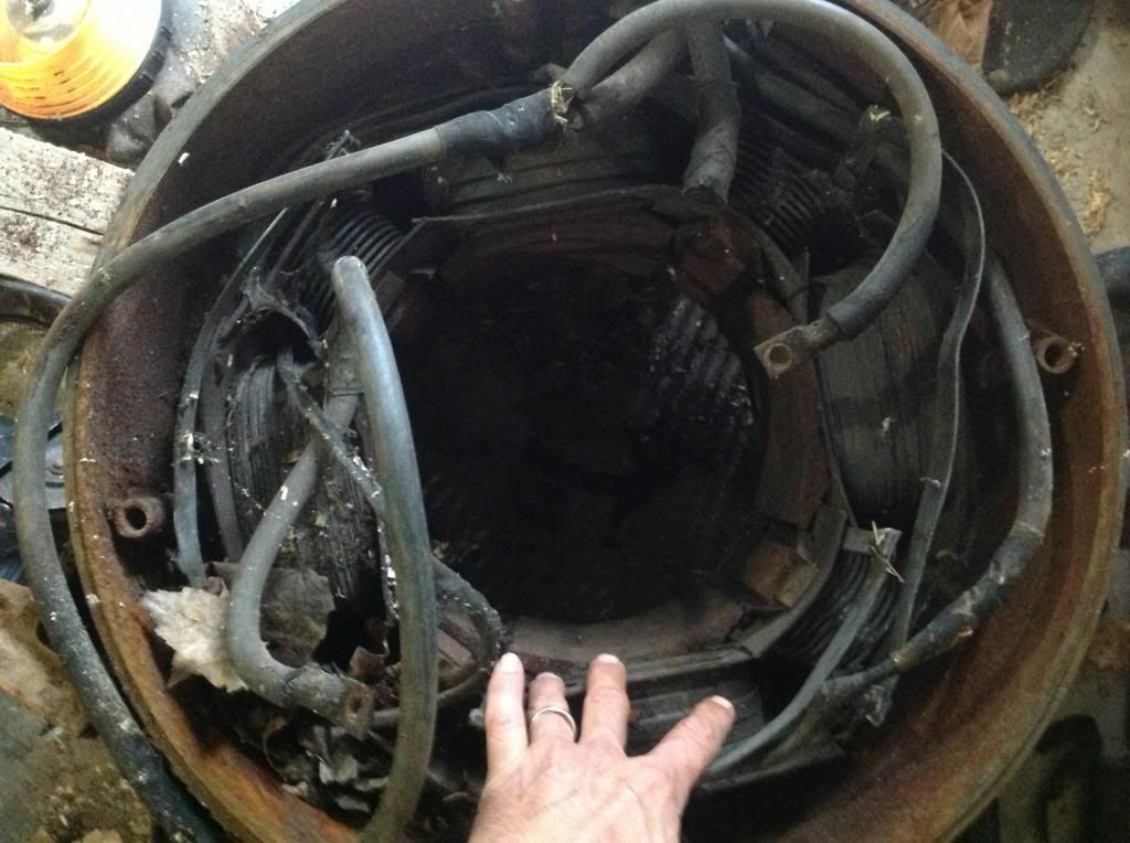
                          Also, since I was bored, I finally had a chance to strip down that big welding machine, nice big 4 pole.

                          Hey Cornboy, wait till you see the wound stators I'm gonna pulse,


                          May try to "re-invent the wheel" with this one. If I leave the interpoles, i could make it an 8 pole.
                          I am going to start making a rotor, where caps can be hidden inside. I've been, and still am,looking for another commutator.

                          Machine

                          Comment


                          • Look here,
                            Onan 203 0125 Commutator Fits DJB 6 0 Welder 5 1 2"Dia | eBay

                            Garry

                            Comment


                            • Thanks Garry

                              The one on mine is 7 " diameter, but I still made him an offer.

                              Comment


                              • Arduino pwm duty cycles

                                Arduino PWM signals

                                --------------------------------------------------------------------------------

                                Hi,

                                I am not new to this thread but have not thought that I had anything to contribute being a fellow student of this technology. But I have a suggestion for Dana and Hitby3K and Sampojo. The pwm pins can have a duty cycle of 0 to 255. This is utilized by the fade program to fade the intensity of the leds. In order to use this effectively for motor control try turning off the leds after the wait period. This would enable you to use the full range of the duty cycle to increase the voltage at the base of the mosfets which will allow more voltage to go to the motor coils. This would increase the torque going to the motor when the gen head gets a larger load and slows the rpms down. If combined with a tachometer you could get automatic speed control by using a select case coupled with several loops that would increase the duty cycle from its current point by say 5 point increments and if the rpms drop below 3400 say 10 point increments . You would be able to determine the appropriate wait period and duty cycle for the load.
                                Here is a simple program that demonstrates the idea.

                                /*
                                Fade 4 LED

                                This example shows how to fade an 4 LEDs on pins 6, 9, 10 and 11
                                using the analogWrite() function.

                                This example code is in the public domain.
                                */
                                int blueLED = 11;
                                int greenLED=10;
                                int redLED = 9;
                                int yellowLED = 6; // the pin that the LED is attached to
                                int brightness = 0; // how bright the LED is
                                int fadeAmount = 5; // how many points to fade the LED by
                                int wait = 100;
                                // the setup routine runs once when you press reset:
                                void setup() {
                                // declare pins 6, 9, 10, 11 to be an output:
                                pinMode(blueLED, OUTPUT);
                                pinMode(greenLED, OUTPUT);
                                pinMode(yellowLED, OUTPUT);
                                pinMode(redLED, OUTPUT);
                                }

                                // the loop routine runs over and over again forever:
                                void loop() {
                                // set the brightness of pin 11:
                                analogWrite(blueLED, brightness);
                                // wait for milliseconds to see the dimming effect
                                delay(wait);
                                // turn off led
                                analogWrite(blueLED, 0);
                                // set the brightness of pin 10:
                                analogWrite(greenLED, brightness);
                                // wait for milliseconds to see the dimming effect
                                delay(wait);
                                // turn off led
                                analogWrite(greenLED, 0);;
                                // set the brightness of pin 9:
                                analogWrite(redLED, brightness);
                                // wait for milliseconds to see the dimming effect
                                delay(wait);
                                // turn off led
                                analogWrite(redLED, 0);
                                // set the brightness of pin 6:
                                analogWrite(yellowLED, brightness);
                                // wait for milliseconds to see the dimming effect
                                delay(wait);
                                // turn off led
                                analogWrite(yellowLED, 0);

                                // change the brightness for next time through the loop:
                                brightness = brightness + fadeAmount;

                                // reverse the direction of the fading at the ends of the fade:
                                if (brightness == 0 || brightness == 255) {
                                fadeAmount = -fadeAmount ;
                                }
                                }

                                This program increases the intensity of the leds every 1/10 of a second or 100 milliseconds. it clearly demonstrates the on and off of each pin. If you want to see a more dramatic fade effect more quickly then reduce the wait period to 10 milliseconds.

                                Cheers,

                                Garry

                                Comment

                                Working...
                                X