Announcement

Collapse
No announcement yet.

My Asymmetric Electrodynamic Machines

Collapse
X
 
  • Filter
  • Time
  • Show
Clear All
new posts

  • Originally posted by Ufopolitics View Post
    Hello to ALL,

    This is an IMPORTANT ISSUE HERE!

    I received an E-Mail (to my ufopolitics@gmail.com) about a very active Member here...Anoop, I don't know if some of you remember Him...But the fact is the following :

    All of the sudden Anoop was not able to Log In into this Forum..??!!

    I will Quote His latest EMail to Me below:


    Now I am directing this Post to Aaron Murakami:

    @Aaron or other Admin:

    How could something like this be possible Aaron?...We will have to take some "Measures/Path/Solutions...In order that something like this will NOT Happen ever again!

    Annop is a very active Member here, basically from my first Thread here to the latest one. And NEVER got involved in ANY Violation of Forum Codes/Rules or ANYTHING RELATED...¿?

    Below I am uploading a Video of His Three Poles Combinations of Prime Mover-Generators...He sent it to me via an App/Box , I believe He lives in Eastern Europe...


    ANOOP VIDEO ON THREE POLES - YouTube


    I wonder how many more Members have gone through same Issues...but never contacted Us...?


    Not good at all guys...Not Good!


    Regards


    Ufopolitics
    Originally posted by Cornboy 555 View Post
    Hello UFO, just wanted to say Thanks, for the great job you are doing with your web site, UFOpolitics.com, it obviously takes a lot of time and effort, and it is great to have all the vids and info in the one condensed spot, for all to see.

    @ Lightworker, i have missed Lester, and Nikko, as well, hope everything is good with them.

    Regards Cornboy.
    I agree with Cornboy 100%. The UFOpolitics.com is brilliant. It is going to become works of reference. Everything under one roof. I like it greatly even though you only have begun (reminds me of a song: We've Only Just Begun)
    All you hard work is already making big impressions.

    Good luck

    warmest regards

    namaste

    light

    Comment


    • Originally posted by Ufopolitics View Post
      Hello Light!


      Regarding your project, I am sorry for your losses...that is a way we make them better and stronger for future testing...that is simply called "Evolution"...my friend.

      Hope you restore everything back to normal soon...and we all get to see those excellent videos you have created so far...

      Ufopolitics
      Once again UFO many thanks for the kind words. I know you are extremely busy. I am here now using your motto in life, "No Sweat." Great way to make a new beginning. Always keep up the spirit my friend. it will propel us to our destiny.

      Warmest Regards

      Namaste

      light
      Last edited by Lightworker1; 07-23-2013, 01:32 AM. Reason: add text

      Comment


      • Originally posted by Ufopolitics View Post
        Farmhand,

        All I would write here to you...as an answer to your post above...

        I LOVE You Man...We are ALL the SAME, exact Carbon deposits from millions of years...We ALL here will eventually disappear within a few years...to let Other "newer carbon structures" to build up and rise future Generations...and so on and on...

        I am not going to respond to your words by another attack...remember, the rule is very simple...by hurting me...you hurt yourself...and all the rest.

        In the Past I did react with some wrong manners...and I did apologize for that and I still do if I need to...and I do apologize to you now whenever I did it.

        I have a reason why I acted like that in the past...and am not trying to justify myself by writing this...But I was getting frustrated because with so many attacks back and forth (including "back" from me)...I could not concentrate in My Main Goal Here...to finish My Disclosure entirely.

        Now, at this point in time...I have dramatically changed (as you could read me now)...why?...just because I have finished demonstrating Majority of my concepts (and am not talking specifically about OU or Free Energy at all)...from Nikola Tesla...to all other bright Scientists, that so many people know so far...for many decades.

        I am talking about Asymmetry...

        Now, I am really busy...so if you forgive me...I have a lot of work to do.

        Thank You and I really appreciate you understanding it.

        God Bless You Farmhand


        Ufopolitics
        I do forgive you, without reservation. Not that I need to as you just allowed
        yourself to forgiven. We are all just human. A lot has been said but I am one
        who allows water to flow under the bridge. Holding grudges takes effort.

        I do understand your frustrations, you see I have been the focus of similar
        frustrations as you have before you came along.

        We all only get a relatively short time on this plane of existence. No time for
        bad Karma. The less of that the better. I won't waste any more of your time,
        and I'll go so far as to say that if I think I can help without disrupting the
        group effort I will.

        Cheers

        Comment


        • Great News

          well I'm for one am very happy that has been sorted. Well done every one and all for your great work! I wish I could help but this is out of my depth of understanding. I am passionately waiting for the UFO kit. No pressure but need by Xmas All the best from a kiwi still enjoying the ride. And to ALL
          Cheers
          Jason

          Comment


          • QP10 coming along

            Intercoil resistance back up to megaohms or open circuit. Should have seen the gunk in one commutator. Brush Spring tension was too severe. First round of tension reduction has gotten the amps to drop back to three for no-load operation. Spins with four brush sets loaded about as easily as it first did with one brush set before, Maybe even a little easier. I still think Spring tension should be relaxed even more And planning a second go at it. Gapped Down on plastic washers between The bearings and The commutator too. Puzzled by the one amp 8000 RPM readings I took A few days ago. I sure would like to get that back. Not sure how I got it but maybe I had accidentally set optimal timing?
            Up, Up and Away

            Comment


            • High Frequency output from motor?

              Hello ufo,

              I was wondering if you knew much about making one of these asymmetric motors into a high frequency generator. I suppose turning it really fast would be the first step, but would there be a better way to wind such a thing with high frequency and amperage in mind. Im going for an old tesla high frequency generator that can run an oscillator. let me know if youve got any ideas!

              Thanks,

              Warrensk

              Comment


              • Deciding what to do a few steps ahead

                Will the imperial be a total standalone system or will it use a transfer switch to grid power? Doesn't phase synchronization need to happen? What about using a grid tie inverter with DC power generation, and feedback to prime mover power sources. I am debating on whether to build a QP10 generator to go with my current motor and try the DC grid tie approach, with some good drop off of amps to it after I build the Monster driver to run it, thus having a good expectation of producing excess power. One of my primary goals is to get to a demonstration platform ASAP before I entertain a more serious move. I have some limitations on handling a bigger imperial project I have to mull over, space, machine tools, etc. I already do have a Mecce Alte generator I could not pass up for the price, used 3KVA, not as powerful as Ufo's, but I'd be happy with it.

                I've been talking to my buddy, boomer trained USN electrician, that when an AC generator locked onto phase of the grid, it locked up the rpm too. If overloaded in generator mode, going out of phase would, with rpm drop, automatically unload the generator and allow it to speed up again and this action would keep the generator in phase. If the load would increase over generator capacity, it would slow the rpm and cps would drop and thus lower voltage too. if a load would eventually not be able to run as voltage would drop from 120 to 110, to 100, etc, it too would eventually drop off the grid and unload it also... So a grid hookup system may not need extensive rpm monitoring and control?

                Any thoughts Ufo?
                Last edited by sampojo; 07-25-2013, 03:24 AM.
                Up, Up and Away

                Comment


                • Three Cents.

                  Originally posted by sampojo View Post
                  Will the imperial be a total standalone system or will it use a transfer switch to grid power? Doesn't phase synchronization need to happen? What about using a grid tie inverter with DC power generation, and feedback to prime mover power sources. I am debating on whether to build a QP10 generator to go with my current motor and try the DC grid tie approach, with some good drop off of amps to it after I build the Monster driver to run it, thus having a good expectation of producing excess power. One of my primary goals is to get to a demonstration platform ASAP before I entertain a more serious move. I have some limitations on handling a bigger imperial project I have to mull over, space, machine tools, etc. I already do have a Mecce Alte generator I could not pass up for the price, used 3KVA, not as powerful as Ufo's, but I'd be happy with it.

                  I've been talking to my buddy, boomer trained USN electrician, that when an AC generator locked onto phase of the grid, it locked up the rpm too. If overloaded in generator mode, going out of phase would, with rpm drop, automatically unload the generator and allow it to speed up again and this action would keep the generator in phase. If the load would increase over generator capacity, it would slow the rpm and cps would drop and thus lower voltage too. if a load would eventually not be able to run as voltage would drop from 120 to 110, to 100, etc, it too would eventually drop off the grid and unload it also... So a grid hookup system may not need extensive rpm monitoring and control?

                  Any thoughts Ufo?


                  Hello Sampojo, one thing i can think of is that the Grid feed unit may have to be approved, for that use, by the power company, or worse still, government regulations, and have a saftey shut down, when the grid goes down for maintainance, or failure, so workers don't get Zapped by your input.

                  There is all sorts of ways to keep the Status Quo.

                  Better to set up completly, off Grid with this stuff, until more widely accepted.

                  I know it means a Battery bank, but Grid Electricity will only keep going up in price, to maintain the infastructure, and with this tech you will be able to keep good batteries nearly for ever.

                  Just my three cents, Cornboy.

                  Comment


                  • In the movies we can often see that some advanced technology are used to protect the important information and prevent it from being lost or people who aiming to get it. Seen from another point we can regard such kind of action as the security method for both people and the information and this is indeed. Right here you will know the desktop cell phone WiFi jammer can also be your best guard and have a good beginning here.When being serious disturbed because of the application of some devices, no doubt another kind of device that can help to conquer the problem and help you to gain the better condition is need and must be used. So now to gain the better condition, various kinds of signal blockers are invented and come into the market to create quality change for people. Such as the cell phone jammers, GPS jammer, WiFi jammers, video jammers and so many other types of jammer products. And what quality changes can they bring you? Then you should be ready to see the following content.

                    Comment


                    • Originally posted by sampojo View Post
                      Will the imperial be a total standalone system or will it use a transfer switch to grid power? ...
                      Unfortunately we are far from your concern just now. You might move a second time before your conern becomes true.
                      Please think in terms of steps:
                      • Get setups running (our state now)
                      • Get setups running along prove of gain
                      • Replicating the gain effect at different setups.
                      • Optimizing gain and replicating at different setups
                      • First practical use of these setups for saving energy (no self run)


                      Further elicitation:
                      • Feedback for self run (novel implications expected)
                      • Connection to grid


                      Interface to the grid is usually done by dedicated converters. Usually they need to be certified and their application needs to be permitted by authorities (at least at so called "civilized" countries) Direct connect and synchronisation is outdated.
                      Fortunately solar and wind power systems paved the way and Chineese converters are available for low price (see eBay). Even cheaper -> second hand products)
                      Future converters will run highest effectivity using SiC FETs or Ga/As FETs. Those are new and just emerging technologies.


                      Example for solar systems:
                      In fact those converters contain a DC to AC sine converter while the sine converter synchronizes with the grid automatically.
                      Apart that the DC input operates over a wide range of input voltage. Automatically it adapts current draw - independently of resulting input voltage - to maximize energy extracted from the source. (MPPT)


                      Please be aware that most technical setups require 20% of getting it running as expected and 80% of safety effort in order to react to any faulty condition in a safe way. Hence we concentrate on those building stons being a novel invention and reuse existing building stones for performing known functions.

                      Please be aware the AC gen head is only a practical means for supplying your private mains. The object of reserch is the motor with its mech output at shaft side. Lots of other applications might be feasible like pumps, air screws, power train for cars .....

                      Please understand: we just start a long way .............

                      Just now I would be excessively happy to draw 100W from my preferred power company or solar system and make 1000W for private use.
                      JS
                      Last edited by JohnStone; 07-25-2013, 03:05 PM.
                      Experts spend hours a day in order to question their doing while others stopped thinking feeling they were professionals.

                      Comment


                      • The Dual Triangles

                        Hey Ufopolitics and all
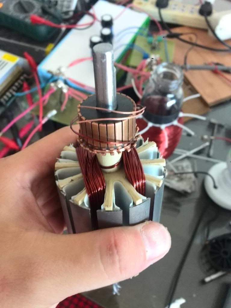
                        I'm kind of late, sorry about that. I choose the Dual Triangles design, for I think it is very torquey. Here is the armature.


                        I use the Bifilar Winding. The pair of two parallel coil together have 90 turns of bifilar windings. Means each single coil have 45 turns. I don't have equipment to test the mechanical output right now. But I do have some interesting readings from my meter.
                        I use a power supply, now a battery ,sorry Ufo I did not follow your advice, this is what I got at the moment. But I put a Huge capacitor band between the power supply and the motor. I set the power supply at 36.2V exactly, and run the motor. In common sense, the motor, the capacitor band, and the power supply are all in parallel, so the voltage of each of them should be the same. But....when I connect the meter's terminals at the point that near the motor, means I wanna test the voltage between the motor input terminals, I connect the meter's terminals behind the capacitor band, near the motor. It reading more than 40V. If I reverse the meter's terminals, means positive to negative, negative to positive, it reads minus several hundreds of volts. And more, my other meter just went crazy, when the motor is running, the other multimeter just can't have a trustable reading, it reads about 18V at the power supply, and hundreds of volts at the motor. I don't know if I'm describing this clearly. The points where should have the exactly same voltage, just show different readings. And if the meter is OK, the voltage near the motor is just higher than the power supply's voltage. Means it is Charging the power supply when running? But why paralleled components have different voltage readings? If I change the motor to a normal motor, everything is back to normal.
                        I think this kind of readings is because that the electric components in side the meter, when come across radiant energy voltage, is causing unpredictable behavior. I just don't know what kind of meter to trust. I think I should use battery instead of the power supply, and choose another meter.
                        Sorry I don't have a video to show this beautiful running, Here is the image.


                        Regards

                        Ming.
                        Last edited by mo19841116; 07-27-2013, 02:05 AM.

                        Comment


                        • About the armature core

                          And hey Ufo,
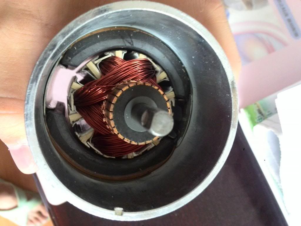
                          When I let the beautiful run for a while, I notice that it is getting a little warm. Then I open it and pull the armature out, and find that it is the core that causing the heat. So I'm thinking that why don't we change the core. Now I've find someone that can cut engineering plastics board neatly. So...I'm planning changing the core to engineering plastics. What do you think about this

                          The thing is, can I use the same design, same diagram, just change the core? Will there be some necessary change due to the changing of core?

                          Thanks man

                          Regards

                          Ming.

                          Comment


                          • Hello Ming, welcome again

                            Originally posted by mo19841116 View Post
                            Hey Ufopolitics and all
                            I'm kind of late, sorry about that. I choose the Dual Triangles design, for I think it is very torquey. Here is the armature.


                            I use the Bifilar Winding. The pair of two parallel coil together have 90 turns of bifilar windings. Means each single coil have 45 turns. I don't have equipment to test the mechanical output right now. But I do have some interesting readings from my meter.
                            I use a power supply, now a battery ,sorry Ufo I did not follow your advice, this is what I got at the moment. But I put a Huge capacitor band between the power supply and the motor. I set the power supply at 36.2V exactly, and run the motor. In common sense, the motor, the capacitor band, and the power supply are all in parallel, so the voltage of each of them should be the same. But....when I connect the meter's terminals at the point that near the motor, means I wanna test the voltage between the motor input terminals, I connect the meter's terminals behind the capacitor band, near the motor. It reading more than 40V. If I reverse the meter's terminals, means positive to negative, negative to positive, it reads minus several hundreds of volts. And more, my other meter just went crazy, when the motor is running, the other multimeter just can't have a trustable reading, it reads about 18V at the power supply, and hundreds of volts at the motor. I don't know if I'm describing this clearly. The points where should have the exactly same voltage, just show different readings. And if the meter is OK, the voltage near the motor is just higher than the power supply's voltage. Means it is Charging the power supply when running? But why paralleled components have different voltage readings? If I change the motor to a normal motor, everything is back to normal.
                            I think this kind of readings is because that the electric components in side the meter, when come across radiant energy voltage, is causing unpredictable behavior. I just don't know what kind of meter to trust. I think I should use battery instead of the power supply, and choose another meter.
                            Sorry I don't have a video to show this beautiful running, Here is the image.


                            Regards

                            Ming.
                            Hello Ming!

                            And welcome again. That is a nice Asymmetric Motor build!...I see you wanted Torque......and you've got it right?

                            That particular Design (Star of David) have basically Three Pairs of Coils...but in reality they are just Three Coils split on both ends of Rotor Core. And You have chosen to go Bifilar...that type reduces resistance and creates a much stronger magnetic field than a single wire winding...This brings some "Attributes/Properties" along...my friend...

                            First, since it is only three coils on this design...and you have not modified the Commutator, by widening-just a bit- the spaces between contact group of comm elements....it is normal that it gets a bit hot...plastic will NOT solve the problem. My opinion is to spread a bit the space between elements, and you should have only Three Spaces to work on each commutator.

                            Or Increase number of turns per coil...increasing resistance (by the way, it is important to read/tell Us your resistance per each Independent Pairs/Coils)

                            That Motor is very strong...and it unleashes Big Amounts of Radiant Energy ...Radiant will try arcing from one comm element to the other...or to ground...wherever SHE could jump to. And I recommend to be very careful with your meters...you definitively could burn them...they are NOT Designed to read that kind of Energy.

                            Strongly suggest to use Diodes, in order that you create a Path for HER to travel through...the same way We did in the other thread to the Static Coils...this time you connect them from your Input Brushes...Remember SHE travels REVERSE to your Normal "Hot" flow.

                            If You analyze the "Timing/Duty" on that particular Motor for each Coil...when feeding it linear from your Power Supply:

                            Your Motor have Three Pairs of Coils...simplifying it for understanding...just Three Split Coils...where ONLY ONE Coil is ON at a Time, based on One side Input only...right?...Therefore, Each Coil is running approximately at 33% Duty Cycle (100/3=33.3333)...That means Coil is On for a 33%...and OFF for a 66.6666%..of the Frequency given by whatever RPM's it runs at...remember from my prior Thread...that Radiant enters at the Off Times, reason why it Generates so much.

                            As you keep learning about this Technology...you will find that the more Pairs of Coils in the Rotor Design...the less the heating on the core...as also less Radiant Energy will be Generated in a "Surge" or High Discharge like you are doing now...

                            Symmetric Motors will not cause this "Jumping" on Meters...just because Radiant is killed before starting to develop....by the constant forced C EMF this Models produce...Therefore Meters will measure everything very "Normal" ...

                            Regards Ming


                            Ufopolitics
                            Principles for the Development of a Complete Mind: Study the science of art. Study the art of science. Develop your senses- especially learn how to see. Realize that everything connects to everything else.― Leonardo da Vinci

                            Comment


                            • G'day UFO
                              I find I am falling further behind as I now have another work Job to do
                              I nearly have finished My Bicycle Motor I decided to utilise the standard motor 36v 250w Chinese motor and power it with the Happy motor circuit
                              I have wound a coil that is reasonably compact That does not heat up and runs the motor unloaded 36v battery output 0.2 amps running 2780revs output is 24v I found it reasonably hard to stop it using 2 pieces of wood to clamp the shaft when it stopped the amps raised a bit the motor did not heat up neither did the circuit and when I released the clamping of the shaft the motor continued to run OK.
                              I ran the motor as fast as I could it reached something like 10500 revs drawing just over 4 amps from the battery and outputting before the diodes something like 50v and after the diodes 105v I had to stop it as I thought it might fly apart.
                              I do not have my camera to take a video at the moment and as I have another Business Job to do so I have to pack everything up out of the way so I can have room to work.
                              In the meantime I have my engineering Friend who is going to mod my 1000 watt Chinese motor it has 4 magnets and 20 poles the wire that was in it was .84mm diam. and had 15 x2 turns each pole and the nearest wire I have on hand is 21 AWG .74mm diam. I feel that perhaps I could use this wire and would be able to fit 17x 2 turns each pole
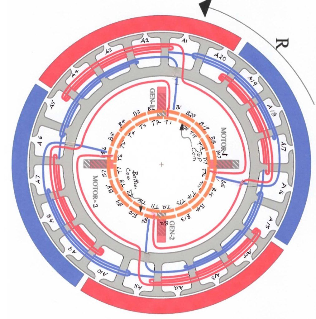
                              The only Winding diagram I could find to match is the Bosch motor I have examined this motor and noted how it is wound Please My friend what wire did you use when winding this motor I have included it here with some notations.
                              Please UFO is this the latest winding for a 20 pole motor and will the thinner wire be OK.


                              Please UFO I have shown the wiring Perhaps I may have it in reverse? Would you examine and verify if I have the correct view

                              I am getting excited now as I am finally getting to finish some real building
                              I intend to use the Arduino to drive this motor

                              Thank you and Kindest regards my Friend


                              Kogs pressing on still

                              Comment


                              • Asymmetric P-20...

                                Originally posted by iankoglin View Post
                                G'day UFO
                                I find I am falling further behind as I now have another work Job to do
                                I nearly have finished My Bicycle Motor I decided to utilise the standard motor 36v 250w Chinese motor and power it with the Happy motor circuit
                                I have wound a coil that is reasonably compact That does not heat up and runs the motor unloaded 36v battery output 0.2 amps running 2780revs output is 24v I found it reasonably hard to stop it using 2 pieces of wood to clamp the shaft when it stopped the amps raised a bit the motor did not heat up neither did the circuit and when I released the clamping of the shaft the motor continued to run OK.
                                I ran the motor as fast as I could it reached something like 10500 revs drawing just over 4 amps from the battery and outputting before the diodes something like 50v and after the diodes 105v I had to stop it as I thought it might fly apart.
                                I do not have my camera to take a video at the moment and as I have another Business Job to do so I have to pack everything up out of the way so I can have room to work.
                                In the meantime I have my engineering Friend who is going to mod my 1000 watt Chinese motor it has 4 magnets and 20 poles the wire that was in it was .84mm diam. and had 15 x2 turns each pole and the nearest wire I have on hand is 21 AWG .74mm diam. I feel that perhaps I could use this wire and would be able to fit 17x 2 turns each pole
                                The only Winding diagram I could find to match is the Bosch motor I have examined this motor and noted how it is wound Please My friend what wire did you use when winding this motor I have included it here with some notations.
                                Please UFO is this the latest winding for a 20 pole motor and will the thinner wire be OK.


                                Please UFO I have shown the wiring Perhaps I may have it in reverse? Would you examine and verify if I have the correct view

                                I am getting excited now as I am finally getting to finish some real building
                                I intend to use the Arduino to drive this motor

                                Thank you and Kindest regards my Friend


                                Kogs pressing on still
                                Hello Kogs!


                                Yes you got it right...except that I have made a mistake in the winding sense of that Diagram, according to Positive start and Magnetic Polarity shown and Rotation displayed. BUT this is easy to resolve using My Right Hand Method...

                                [IMG][/IMG]

                                The way I did this (BOSCH Motor/BADSEY Scooter) is based on the "P-Series" Winding. So, Your T1-B1 would be your "P-1", negative and positive terminals, at Pair One...then from there you keep going into P2, P3...so on.

                                The Imperial Winding is a P28 also...so if you watch My Tutorials:

                                Asymmetrical Winding Part 1 - YouTube

                                Asymmetrical Winding Part 2 - YouTube

                                Asymmetrical Winding Part 3 - YouTube

                                As it will help you to get the right way to do this...same exact thing, except you are winding 20 poles instead of 28...

                                On the BOSCH I used 18 Gauge wire (awg), and did like 20-21 turns per Coil...42 total on Pair. Meaning, South-21 Turns, North 21 Turns.


                                A finer wire would not project a strong magnetic Field(not to high speed, not too strong Poweer (torque)...however, it will give you very low amperage draw...Your choice according to application there.


                                Kind Regards Kogs!!


                                Ufopolitics
                                Principles for the Development of a Complete Mind: Study the science of art. Study the art of science. Develop your senses- especially learn how to see. Realize that everything connects to everything else.― Leonardo da Vinci

                                Comment

                                Working...
                                X