 Tweet
Tweet
Simple Sampojo...
Hello Sam,
It is very simple my friend...just get some nice and strong Needle Nose Pliers (I've got Snap On's...and NOT making any advertisement to them...but they are great...however, any other brand will do it)
First CUT the wire you will be extracting, and try to cut it leaving enough length to grab it with pliers. Think you must leave a section to take coils apart...but taking that wide tape out...I believe you've got plenty of exposed wire there...
Insert Pliers in the Interior wire that goes to Coil, then roll it towards the Outer side of Commutator...and wire should slide out through the gap, with the pressed and widened side also. In other words, you will be pulling wire from Inside-Out of Commutator...
I see You have at Comm two wires per segment...so, first try inserting one side of pliers in between the two wires, close them and roll them out...to get One out first...then the next.
Try to lean pliers on the Bottom side of Comm first, then roll it outwards.
[IMG]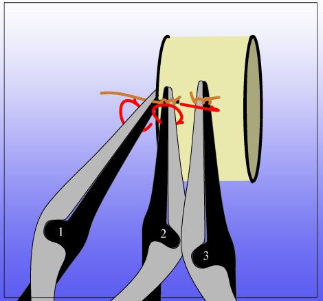 [/IMG]
You could use a plastic putty knife or a paint stick...in order that pliers roll on top of their surface and not on top of Commutator copper...in order not to mark it/scratch it/deform elements.
That method should work out very smooth.
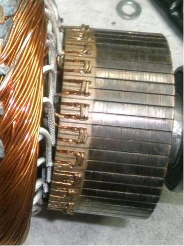
Leaving One Out and seven "ON" segments is an Awesome idea!...that way you would not alter/modify the commutator...so it could be re-used for another type of winding...
Depending on brush size (width) you could use 6-On/2-Off also and see results...as long as there is never a "dead contact"(Brush width touching only two Off Segments ...then motor would not start.
So Brush MUST be wider than Two Segments to work at 6-2.
7-1 will definitively work.
Regards
Ufopolitics
Originally posted by sampojo
View Post
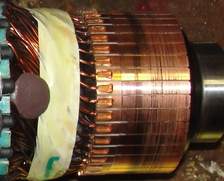
 , eight of these comm (half) segments must be wired together.
Hello Sam,
It is very simple my friend...just get some nice and strong Needle Nose Pliers (I've got Snap On's...and NOT making any advertisement to them...but they are great...however, any other brand will do it)
First CUT the wire you will be extracting, and try to cut it leaving enough length to grab it with pliers. Think you must leave a section to take coils apart...but taking that wide tape out...I believe you've got plenty of exposed wire there...
Insert Pliers in the Interior wire that goes to Coil, then roll it towards the Outer side of Commutator...and wire should slide out through the gap, with the pressed and widened side also. In other words, you will be pulling wire from Inside-Out of Commutator...
I see You have at Comm two wires per segment...so, first try inserting one side of pliers in between the two wires, close them and roll them out...to get One out first...then the next.
Try to lean pliers on the Bottom side of Comm first, then roll it outwards.
[IMG]
 [/IMG]
You could use a plastic putty knife or a paint stick...in order that pliers roll on top of their surface and not on top of Commutator copper...in order not to mark it/scratch it/deform elements.
That method should work out very smooth.
Leaving One Out and seven "ON" segments is an Awesome idea!...that way you would not alter/modify the commutator...so it could be re-used for another type of winding...
Depending on brush size (width) you could use 6-On/2-Off also and see results...as long as there is never a "dead contact"(Brush width touching only two Off Segments ...then motor would not start.
So Brush MUST be wider than Two Segments to work at 6-2.
7-1 will definitively work.
Regards
Ufopolitics
 Seems like it could work. Tight for a crimp tool. Wish I could use solder but it is forbidden by UFO .
Comment