Announcement

Collapse
No announcement yet.

My Asymmetric Electrodynamic Machines

Collapse
X
 
  • Filter
  • Time
  • Show
Clear All
new posts

  • Simple Sampojo...

    Originally posted by sampojo View Post
    Hi gang,

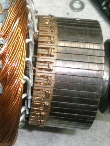
    Looking a my Baldor comms, notice how they machine pressed the comm gap closed over the wire. How is this corrected and with what tools short of taking it to a machine shop?


    Can the wires be yanked out? Use a little pry tool as in Ufo's Imperial winding video to get the gap open? maybe a small file next? Can a drill bit be used? Any and all of these things? I guess use my drill press to drill the gaps out a bit with a smallish bit, less than the diameter of the selected gauge I would use?

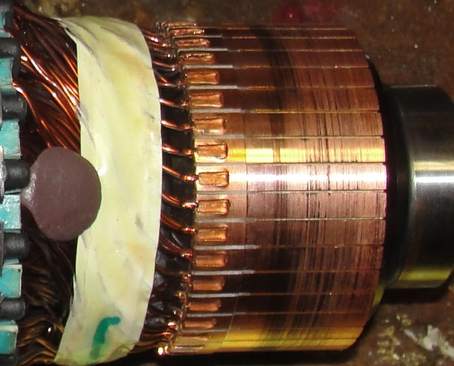
    Here is Ufo's Imperial commutator.


    I guess you see the doubled wire bc Ufo said the gaps on his comm was for 16 ga so the second wire is 16 ga to lock in his 18 ga. and then cross into the next half comm segment to tie them together, as even the Imperial commutator has 56 segments for a 28 pole motor, just a my baldor has 40 segments for a 20pole motor. (I guess they do this for some benefit of that symmetric winding?)

    So if you try to put some taper in the slot, just shove the wire up into it and press it in, gap it over to the second half segment, cram it in and thats it? Retap the gap with a flat punch to maybe smash the gap down again a little bit?

    Since I will be making a giant RS motor , eight of these comm (half) segments must be wired together.

    Hey Ufo,

    You mentioned widening a gap between comm segment groups to cut sparking maybe on the comm designed this way since it would be in contact with one coil so long. What about just leaving one segment out and wiring only 7 together?

    Thanks, Sam


    Hello Sam,

    It is very simple my friend...just get some nice and strong Needle Nose Pliers (I've got Snap On's...and NOT making any advertisement to them...but they are great...however, any other brand will do it)

    First CUT the wire you will be extracting, and try to cut it leaving enough length to grab it with pliers. Think you must leave a section to take coils apart...but taking that wide tape out...I believe you've got plenty of exposed wire there...

    Insert Pliers in the Interior wire that goes to Coil, then roll it towards the Outer side of Commutator...and wire should slide out through the gap, with the pressed and widened side also. In other words, you will be pulling wire from Inside-Out of Commutator...

    I see You have at Comm two wires per segment...so, first try inserting one side of pliers in between the two wires, close them and roll them out...to get One out first...then the next.

    Try to lean pliers on the Bottom side of Comm first, then roll it outwards.

    [IMG][/IMG]

    You could use a plastic putty knife or a paint stick...in order that pliers roll on top of their surface and not on top of Commutator copper...in order not to mark it/scratch it/deform elements.


    That method should work out very smooth.

    Leaving One Out and seven "ON" segments is an Awesome idea!...that way you would not alter/modify the commutator...so it could be re-used for another type of winding...

    Depending on brush size (width) you could use 6-On/2-Off also and see results...as long as there is never a "dead contact"(Brush width touching only two Off Segments ...then motor would not start.

    So Brush MUST be wider than Two Segments to work at 6-2.
    7-1 will definitively work.


    Regards


    Ufopolitics
    Last edited by Ufopolitics; 09-18-2013, 03:54 AM.
    Principles for the Development of a Complete Mind: Study the science of art. Study the art of science. Develop your senses- especially learn how to see. Realize that everything connects to everything else.― Leonardo da Vinci

    Comment


    • Ufo, Quick follow-up on fastening wire to comm segs

      And so the fastening method would be to stick the new wire into the holes of the old wire (paired as to jump between segments to join them) and just carefully tap the segment again where there is that rectangular punched pit to squeeze the wires tight?

      Ah, I think I see now, try to roll the wire out on the top of the segment and this will re-spread the gap?

      I suppose if the wire comes out the back of the segment, I might be able to put a wire back in the hole.

      The problem will come if a wire breaks. Just try to work the back of the segment to re-shape and re-spread the gap and dig the wire out as you go I suppose.

      Bottom line is I should try to get to gaps like the Imperial comm and fasten things the same way maybe by just tapping the new wire into the crack and bringing it out on top is the best, as shown on the Imperial?


      Edit: Nah they are just breaking off, not really budging. Can I put a 4-40 tapped hole and use a screw to hold the wire?
      Won't work, right? always will come loose.

      I could get my dremel tool out with a diamond blade to put that gap back and then I can get a small screwdriver blade in there to finish it... too hard, copper aint that soft.

      Its the screw or nuthin'

      thanks Ufo.
      Last edited by sampojo; 09-18-2013, 06:20 AM.
      Up, Up and Away

      Comment


      • Tooling...

        Originally posted by sampojo View Post
        And so the fastening method would be to stick the new wire into the holes of the old wire (paired as to jump between segments to join them) and just carefully tap the segment again where there is that rectangular punched pit to squeeze the wires tight?

        Ah, I think I see now, try to roll the wire out on the top of the segment and this will re-spread the gap?

        I suppose if the wire comes out the back of the segment, I might be able to put a wire back in the hole.

        The problem will come if a wire breaks. Just try to work the back of the segment to re-shape and re-spread the gap and dig the wire out as you go I suppose.

        Bottom line is I should try to get to gaps like the Imperial comm and fasten things the same way maybe by just tapping the new wire into the crack and bringing it out on top is the best, as shown on the Imperial?


        Edit: Nah they are just breaking off, not really budging. Can I put a 4-40 tapped hole and use a screw to hold the wire?
        Won't work, right? always will come loose.

        I could get my dremel tool out with a diamond blade to put that gap back and then I can get a small screwdriver blade in there to finish it... too hard, copper aint that soft.

        Its the screw or nuthin'

        thanks Ufo.
        Hello Sam,

        The Chisel to do this pressing in...MUST BE smaller than elements gap.

        Also, the end point of that Chisel MUST BE ROUNDED OFF...no sharp edges or it will cut wires.

        If the wires brakes on the rolling process inside gap...then do the Carbide Dremel Disc "thing"...

        Using a bigger than gap piece of copper wire on top would do the Riveting Process...and actually that is the wire to gently hammer with chisel.


        Regards


        Ufopolitics
        Principles for the Development of a Complete Mind: Study the science of art. Study the art of science. Develop your senses- especially learn how to see. Realize that everything connects to everything else.― Leonardo da Vinci

        Comment


        • Hi Guys

          There has been some great progress on this thread, I have been waylaid by other events. But for us beginners a video of the asymmetric motor with a diode between the motor negative to positive and showing how via PWM the energy is recycled:

          UFO Asymmetric motor with diode across input to output - YouTube
          Kind regards

          John

          Comment


          • Baldor comm prob

            Ufo, I don't think I can get the old wires out or the gaps opened to install any new wire on the segments. Nuthin' gives, & wires break.

            I want to put a 2-56 tapped hole instead and use a 3/8" steel screw with washer & lock washer to hold the wire down. Bad idea?

            Thanks,

            Sam
            Up, Up and Away

            Comment


            • P66LR006 motor

              Greetings:

              Well, I took a chance and purchased two P66LR006 Imperial motors. (Kogs, JS, I know you warned me, but I just couldn't resist!)

              They came in today and are huge! 50 pounds each.

              I took one apart. They are four brush and the rotor has 33 segments. (I was hoping for 36 or an even number.) (Yes Kogs/JS, you warned me....)

              It looks like I will have to replace the shafts....but will make that judgement after removing the fan and getting a measurement. Also, will probably use two rear end plates/brush mounts on each motor. (Mounting the brush holder to the front motor cap doesn't look promising.)

              An engineer with Imperial was kind enough to send me a sketched diagram and parts list, so there should be no confusion about which parts to order.

              Figure to be cleaning armatures this weekend.....

              pics below,

              glen
              Attached Files

              Comment


              • Originally posted by john_g View Post
                Hi Guys

                There has been some great progress on this thread, I have been waylaid by other events. But for us beginners a video of the asymmetric motor with a diode between the motor negative to positive and showing how via PWM the energy is recycled:

                UFO Asymmetric motor with diode across input to output - YouTube
                Kind regards

                John

                Hello John G, glad you are back, thanks for the vid, what are you driving there, a Gen?, interesting looking device.

                Regards Cornboy.

                Comment


                • Originally posted by GlenWV View Post
                  Greetings:

                  Well, I took a chance and purchased two P66LR006 Imperial motors. (Kogs, JS, I know you warned me, but I just couldn't resist!)

                  They came in today and are huge! 50 pounds each.

                  I took one apart. They are four brush and the rotor has 33 segments. (I was hoping for 36 or an even number.) (Yes Kogs/JS, you warned me....)

                  It looks like I will have to replace the shafts....but will make that judgement after removing the fan and getting a measurement. Also, will probably use two rear end plates/brush mounts on each motor. (Mounting the brush holder to the front motor cap doesn't look promising.)

                  An engineer with Imperial was kind enough to send me a sketched diagram and parts list, so there should be no confusion about which parts to order.

                  Figure to be cleaning armatures this weekend.....

                  pics below,

                  glen


                  Hello GlenWV, maybe you could alter the PM's, and wire the motor as a Large three pole design. Don't know if you could get enough wire in there for that, spanning 11 poles, maybe small wire and lots of turns?.

                  Maybe even a different way of populating all the 11 poles with wire as 1 coil.

                  Most certainly, UFO, is the one to comment here.

                  Thinking out loud, Cornboy.

                  Comment


                  • Originally posted by Cornboy 555 View Post
                    Hello John G, glad you are back, thanks for the vid, what are you driving there, a Gen?, interesting looking device.

                    Regards Cornboy.
                    Hi Cornboy

                    Yes its a generator. The frame is from the small bedini kit, keeping the 3 pole rotor with small neos. There are 7 pickup coils, each feeding into a FWBR @ 45volts.

                    Regards

                    John

                    Comment


                    • connectors?

                      @Sampojo
                      I thought that I read somewhere that someone had cut the leads long and then used crimp connectors to connect the new wire to the old. Probably wouldn't work on small motors but just an idea that might work.

                      Cheers

                      Garry

                      Comment


                      • Baldor commutator prob

                        Originally posted by GChilders View Post
                        @Sampojo
                        I thought that I read somewhere that someone had cut the leads long and then used crimp connectors to connect the new wire to thelold. Probably wouldn't work on small motors but just an idea that might work.

                        Cheers

                        Garry

                        Thanks Garry!

                        Hmmm... Veddy intedesting. Seems like it could work. Tight for a crimp tool. Wish I could use solder but it is forbidden by UFO . Gas weld w/pencil torch still tight for that too. It's not a lot of work to drill and tap though, and I am talking myself into thinking the screw won't come loose with a lock washer, giving you a nice reusable mechanical connection to the commutator.
                        Up, Up and Away

                        Comment


                        • Hello Sam
                          I'm not saying that a screw is the way to go but if you are going to do that, I would use a set screw and set lock-tight over the top to make sure that if brushes move, they would not hit the screw.
                          Dana
                          "Today's scientist have substituted mathematics for experiments and they wander off through equation after equation and eventually build a structure which has no relation to reality."
                          Nikola Tesla

                          Comment


                          • loctite

                            @sampojo
                            I am not sure of the temperatures that Loctite can handle but a screw would definitely need locking threads in addition to Loctite. I think that I would prefer the crimp connectors if you have adequate room. Vibration in any motor will loosen screws. Locking threads and Loctite should eliminate that problem like Dana said.

                            Cheers,

                            Garry

                            Comment


                            • P66LR006 motor

                              Originally posted by Cornboy 555 View Post
                              Hello GlenWV, maybe you could alter the PM's, and wire the motor as a Large three pole design. Don't know if you could get enough wire in there for that, spanning 11 poles, maybe small wire and lots of turns?.

                              Maybe even a different way of populating all the 11 poles with wire as 1 coil.

                              Most certainly, UFO, is the one to comment here.

                              Thinking out loud, Cornboy.
                              I'm always glad to hear people thinking.... (sometimes, I answer myself!)

                              On page 25, Mr. UFO speaks with KEhYo77 about a 17 pole motor.

                              So, if a 17 pole unit can be done, then there may be hope for my 33 pole unit.

                              You are correct: Mr. UFOPolitics is the guy!! (I'm hoping for some directions.)

                              glen

                              Comment


                              • Hello Glen

                                Originally posted by GlenWV View Post
                                I'm always glad to hear people thinking.... (sometimes, I answer myself!)

                                On page 25, Mr. UFO speaks with KEhYo77 about a 17 pole motor.

                                So, if a 17 pole unit can be done, then there may be hope for my 33 pole unit.

                                You are correct: Mr. UFOPolitics is the guy!! (I'm hoping for some directions.)

                                glen
                                Hello Glen,

                                I did see all the pictures of the 33 Imperial Motors...and I believe it could be worked out to be a P33...and you are right...if a P17 and later on a P21...why not a P33?

                                Also Cornboy Three Pole suggestion seems to be very interesting...a 3 Poles with Four Stators...

                                Whenever I have a chance I will do the CAD work...it may be a bit weird (very asymmetric)...but let's see how it turns out...


                                Kind Regards


                                Ufopolitics
                                Principles for the Development of a Complete Mind: Study the science of art. Study the art of science. Develop your senses- especially learn how to see. Realize that everything connects to everything else.― Leonardo da Vinci

                                Comment

                                Working...
                                X