Announcement

Collapse
No announcement yet.

My Asymmetric Electrodynamic Machines

Collapse
X
 
  • Filter
  • Time
  • Show
Clear All
new posts

  • hey UFO

    I have 3 slip rings on the brushes.

    Machine...just now, after I was going over and editing my post above to Garry on Tesla's Patent...I just got an idea on our Drum design...

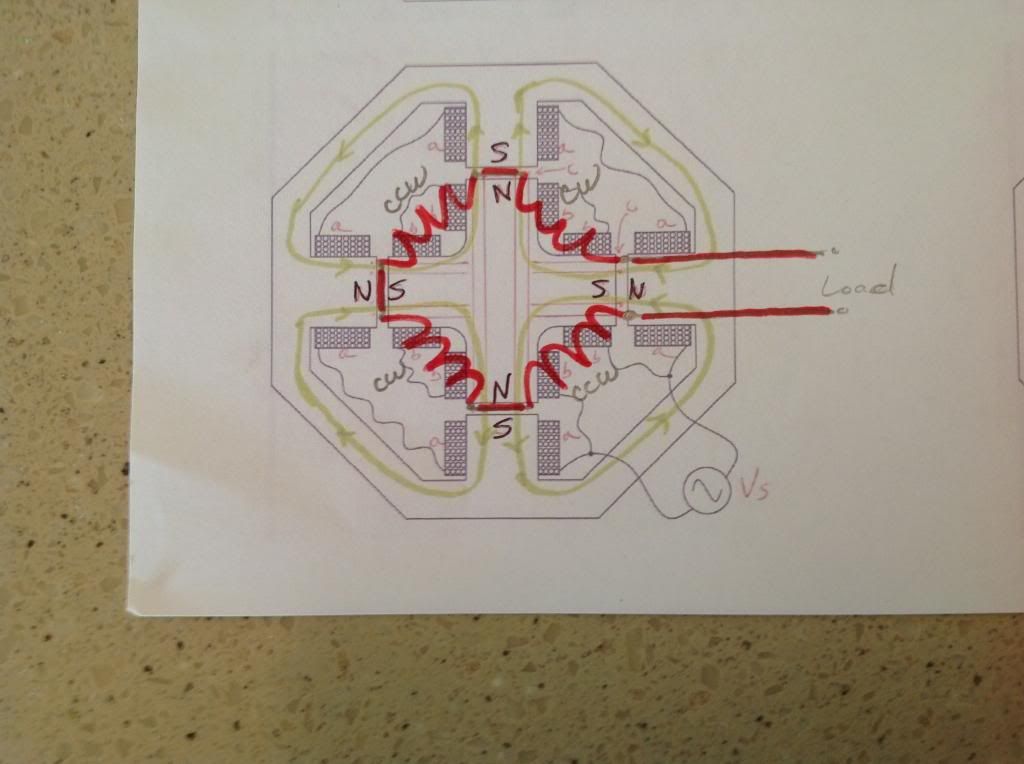
    Tesla uses the Toroidal Design a lot on His Induced Coils like in the Patent above where He "Fuses" Motor and Generator...

    Then why don't we use a Toroidal Coil...wrapped around a very thin and plain Cylindrical Drum?

    I You notice Tesla wounded in, Four Coils at Right Columns Diagram/Fig 1a,2a,3a...representing the Generator Induced Coils Toroidal Structure...leaving a space between wraps...space we could use for attachment/fastening to Upper/Lower rotating structures...then you DO could make it in Aluminum...since a Toroid would project its magnetic fields WITHIN and "INTERNALLY" the cylindrical structure...and NOT towards outer space to stators...

    How come I did not think about this before?...Idk...and I have been saying over and over, about Tesla Toroidal Generators Induced Coils advantages...

    The only thing at risk here is that copper would be exposed between Stators/Exciters steel laminations...and a very tiny misalignment could destroy winding...so, we could use a fiberglass hot temp paper and epoxy them very tight...in order to protect them on both sides, inner-outer.
    That was my plan with the fins. I was going to wrap around the drum, fins to keep coils in place.


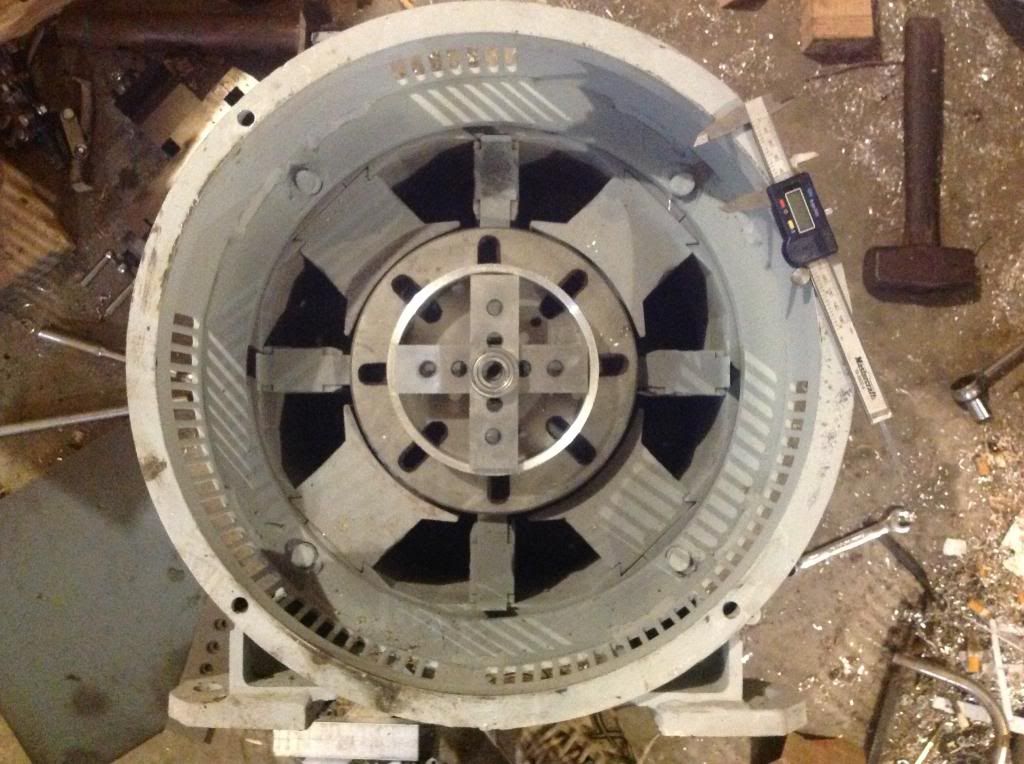
    also, I set up the stators, are you sure the interpoles are too small, they seem to be a good size for inner stator. I'll post a pic tonight so you can see what it would look like. it looks good to me.
    Last edited by machinealive; 10-11-2013, 03:12 PM.

    Comment


    • Great point John...

      Originally posted by JohnStone View Post
      I recommend to anybody checking his new wond motor with one single winding first. Unfortunately UFO motors have more degrees of freedom in jamming things together and thus they might run in low level mode.
      I had similar problmes with my first motor and got things straight by prcedure below.

      Usually we wind motors conforming to UFOs drawing. We wind first coil being placed well aligned with a N pole.
      • Check first if brushes in drawing are positioned like at your motor
      • Get this coil and solder wires to commutator segments.
      • Energize coil as proposed by drawing and check for pole direction.
      • Check stator for pole direction
      • Insert armature into motor.
      • Rotate armature to be positioned pole exactly like in drawing to a N magnet.
      • Energize coil again like shown in drawing.
      • Check for correct movement.


      For a pole checker I stick a small magnet N/S line 90° to tooth pick. Holding the toothpick between two fingers the magnet will rotate freely indicating pole at stator or pole at rotor.
      JS
      Hello John,


      Great point you are bringing here!...Now, the only part I disagree with You is (underlined)below:

      Usually we wind motors conforming to UFOs drawing. We wind first coil being placed well aligned with a N pole.
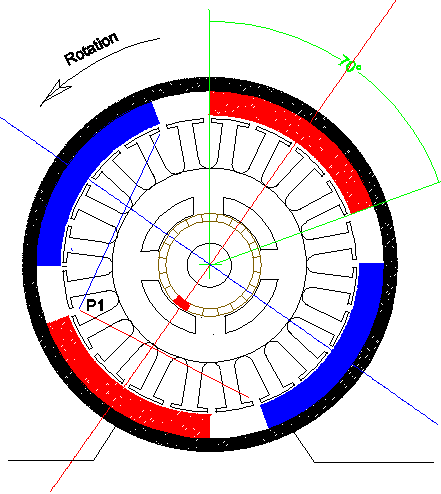
      The main point when setting our first coil (P1) positioning, related to our Stators (North or South...or BOTH )...is about to set the contact Brush-Commutator Element, PASSING the Stator Bisector towards our desired Rotation Sense by a few degrees...but NEVER, EVER, aligning them well centered with stator bisectors.


      Coils MUST BE at least One Degree (1º) OFF from Stator Dead Center at Energizing Time.

      If We set the Rotor Coil to fire (get energized) one degree to right related to stator dead center...then our Motor would rotate CW...or to our right.

      If We set the Coil to fire (get energized) one degree to left related to stator dead center...then our Motor would rotate CCW...or to our left.

      If our winding considers Pairs, or Two Coils in series...then We Must look at BOTH Coils bisectors alignment related to TWO Stators Bisectors setting...see below pic:

      [IMG][/IMG]

      First, We must learn to "see" how our Coils Bisectors project towards Stators...and that very center "needle" is our alignment gauge needle related to Curved Stators dead center line...or Bisector.


      Hope You "see" it now John et All.


      Warm regards


      Ufopolitics
      Last edited by Ufopolitics; 10-11-2013, 03:25 PM.
      Principles for the Development of a Complete Mind: Study the science of art. Study the art of science. Develop your senses- especially learn how to see. Realize that everything connects to everything else.― Leonardo da Vinci

      Comment


      • This is what I meant...

        Originally posted by machinealive View Post
        hey UFO

        I have 3 slip rings on the brushes.


        That was my plan with the fins. I was going to wrap around the drum, fins to keep coils in place.


        also, I set up the stators, are you sure the interpoles are too small, they seem to be a good size for inner stator. I'll post a pic tonight so you can see what it would look like. it looks good to me.


        Machine,

        This is what I meant...

        [IMG][/IMG]


        The holes/columns in Drum, are meant to fit a thread to tighten to upper-lower rotating rings...or just holes to house long crossing bolts/washers/nuts......while the "column" housing the holes...serves to hold coils not to jump on other side...instead of "fins"...

        You could fill all that Gap with Copper (Red Shaded Area on Close Up Section Below)...so, the thinner the inner/center ring at drum...the better...wires must be pressed very vertical and very tight, conforming a "solid like" vertical ring-wall...

        [IMG][/IMG]


        This is it
        , my friend...a fusion between Figueras and Tesla concepts...please do NOT share it with anyone!!!... ...let's keep it very confidential...


        Warm regards


        Ufopolitics
        Last edited by Ufopolitics; 10-11-2013, 04:29 PM.
        Principles for the Development of a Complete Mind: Study the science of art. Study the art of science. Develop your senses- especially learn how to see. Realize that everything connects to everything else.― Leonardo da Vinci

        Comment


        • Refresh to see Edits...

          Machine, Refresh screen (F5) to see new Edits...

          Have to go...


          Regards


          Ufopolitics


          Will delete this post later on.
          Principles for the Development of a Complete Mind: Study the science of art. Study the art of science. Develop your senses- especially learn how to see. Realize that everything connects to everything else.― Leonardo da Vinci

          Comment


          • Beautiful UFO, that is a top secret drawing.

            So I agree, fins are unnessecary, I had it in my head, where coils may bunch up in centre as we wind, so fins would keep coils neater. Also we would see when coils were becoming uneven, and if we ended up needing to put an outer or inner cover on to keep wires secure, we could bolt cover to the fins ( leave a fin at each 90*, thicker to bolt to). If no fins, we will have to notch ends of drum, to keep wires in place, I'm sure of it, as we wind, the coils are going to get squeezed to centre, on inner side of drum.

            I met an old machinist today, he believes he has a press (260 ton),which will press the old stators out.. That would save so much work. Then different materials could be exchanged easy. I would try aluminum, of coarse, eventually.
            Now, are you winding 4 different coils. I thought I would use 1 and change direction at each 90*. Then wind a large ga. Coil over it. Plus with each fin at 90*, we know more precisely, were to start next coil if we want more phases.

            Later, UFO Comrade.

            Machinealive

            Comment


            • PM poles

              @UFO
              I think I have it, but am not sure every one does. It seems like in the picture of the Tesla patents that the south pole is not shown in the drawing but is implied by the broken line on the north pole of the permanent magnets, and vice versa on the south poles. As there is only one pole per magnet being depicted in the color diagrams it is easy to misinterpret which side of the magnet is being depicted as north or south. I am no longer confused but since I was the first time that I replicated a motor, it may be that I am not the only one that has been. On page 54 post 1613 in the thread JohnG speaks to the confusion that I experienced on my first motor replication. I thought that I did every thing correctly but could not get the motor to run because of the magnets improper alignment to the rotor. It was a fairly simply fix. I just reversed the positive and negative leads to reverse the direction of the poles on the electromagnets and was off to the races. I had not timed them at that time and was able to get better performance by adjusting the brushes. At any rate the torque was so much better with the asymmetrical wind than the original. I could stop the original by grabbing the shaft with my thumb and forefinger and could not stop the asymmetrical wind motor doing the same. I was very impressed to say the least. That encouraged me to delve deeper into the technology. I was also very impressed with the increase in rpm when rerouting the generator side into the drive side of the motor, a very significant increase in rpm resulted.

              Cheers

              Garry

              Comment


              • UFO

                One last thing.

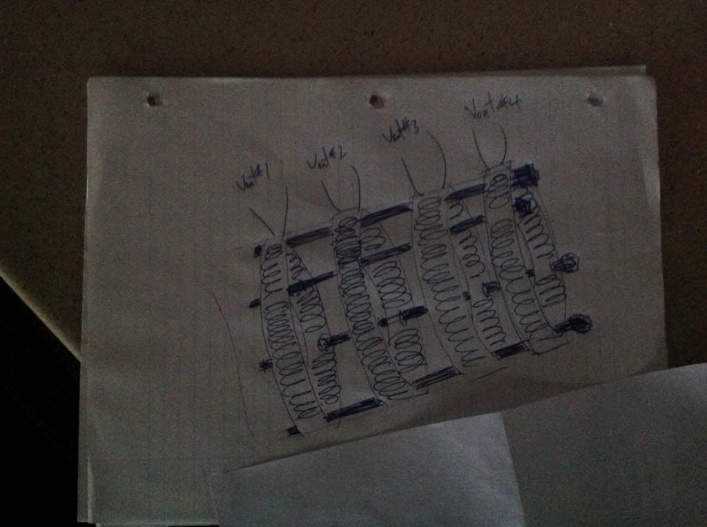
                What if we simply wound 4-6 toroids, and stacked them. You could wind any one of them different, get whatever feed you want off a different ga./#turn pre wound, custom made toroids.

                Just stack 'em.

                UFO, could you please draw a cad, with 4 toroids stacked together, with spacers between them. Your 4 bolts running lengthwise securing them together. For our drum.

                Like this but nicer


                This would make a much stiffer design, keeping wires tight, but less space for useable coil.

                Comment


                • Originally posted by GChilders View Post
                  @UFO
                  I think I have it, but am not sure every one does. It seems like in the picture of the Tesla patents that the south pole is not shown in the drawing but is implied by the broken line on the north pole of the permanent magnets, and vice versa on the south poles. As there is only one pole per magnet being depicted in the color diagrams it is easy to misinterpret which side of the magnet is being depicted as north or south. I am no longer confused but since I was the first time that I replicated a motor, it may be that I am not the only one that has been. On page 54 post 1613 in the thread JohnG speaks to the confusion that I experienced on my first motor replication. I thought that I did every thing correctly but could not get the motor to run because of the magnets improper alignment to the rotor. It was a fairly simply fix. I just reversed the positive and negative leads to reverse the direction of the poles on the electromagnets and was off to the races. I had not timed them at that time and was able to get better performance by adjusting the brushes. At any rate the torque was so much better with the asymmetrical wind than the original. I could stop the original by grabbing the shaft with my thumb and forefinger and could not stop the asymmetrical wind motor doing the same. I was very impressed to say the least. That encouraged me to delve deeper into the technology. I was also very impressed with the increase in rpm when rerouting the generator side into the drive side of the motor, a very significant increase in rpm resulted.

                  Cheers

                  Garry
                  Hey Garry, How did you wire the gen side to the motor side, pole to pole, pos to pos or pos to minus? have to try that. Sounds like a hobby size motor? and which patent numbers of Tesla are you referring to? I think when john_G just put the diode between the battery connections, P0st 5455 and got a speed up was awesome. Got to check out all these hookups for performance improvements.
                  Last edited by sampojo; 10-11-2013, 11:19 PM.
                  Up, Up and Away

                  Comment


                  • Originally posted by Ufopolitics View Post
                    Hello John,


                    Great point you are bringing here!...Now, the only part I disagree with You is (underlined)below:


                    The main point when setting our first coil (P1) positioning, related to our Stators (North or South...or BOTH )...is about to set the contact Brush-Commutator Element, PASSING the Stator Bisector towards our desired Rotation Sense by a few degrees...but NEVER, EVER, aligning them well centered with stator bisectors.


                    Coils MUST BE at least One Degree (1º) OFF from Stator Dead Center at Energizing Time.

                    If We set the Rotor Coil to fire (get energized) one degree to right related to stator dead center...then our Motor would rotate CW...or to our right.

                    If We set the Coil to fire (get energized) one degree to left related to stator dead center...then our Motor would rotate CCW...or to our left.

                    If our winding considers Pairs, or Two Coils in series...then We Must look at BOTH Coils bisectors alignment related to TWO Stators Bisectors setting...see below pic:

                    [IMG][/IMG]

                    First, We must learn to "see" how our Coils Bisectors project towards Stators...and that very center "needle" is our alignment gauge needle related to Curved Stators dead center line...or Bisector.


                    Hope You "see" it now John et All.


                    Warm regards


                    Ufopolitics
                    UFO


                    Should we set the brushes as close as possible to 1 degree? Between poles 3 & 4?


                    Midaz

                    Comment


                    • UFO

                      Here is a pic of gen again. Are you positive, the interpoles are too small? They would be a good match for inner stators.

                      Maybe we should keep this separate from this thread, so as not to confuse or mix things up here. It's your call UFO.

                      Comment


                      • @ machinealive

                        I like having your project here. It's easy to follow and interesting. Lovin it! Keep up the great work!

                        Keep it Clean and Green

                        Midaz

                        Comment


                        • Originally posted by Ufopolitics View Post
                          Kogs...

                          I was referring to Brushes positioning related to Stators (Magnets)...NOT Commutators...
                          Regards


                          Ufopolitics
                          G'day UFO
                          I have been peering into your posts and to some extent I think I understand what you are saying I have spent a day trying to use Draft Sight drawing program as the one I have been using first the last 20 odd years is Draught Choice and not supported any more and I found this one about 12 months ago and have been too busy to learn how to us it


                          Kogs My1060 20 Pole.dwg
                          Please my friend would you peruse this drawing and see if I have a correct understanding of it I have only shown the wiring of P1 and the brushes are at the centre of each stator magnet.
                          I really want to get this correct before I continue
                          Also would this motor be able to run in reverse so as I can reverse the MY 1000w Motor which is similar in size diam. poles and stator magnets just longer in the body. I will use this motor in the Tricycle I will build Next Then onto the P56's
                          I really appreciate your diligence and patience in helping all those active here
                          Everyone here is trying to help each other and not like most other forums where they always seem to keep what they know to themselves
                          Kindest Regards

                          Kogs making sure he gets it right

                          Comment


                          • Kogs
                            Although the brushes are at center of stator, the coil centers are offset as shown and will pull one way only. If you center the coils at brush center the motor could rotate both ways but unpredictable and need a push in desired direction. Tuning would also be difficult as I see it.
                            Dana
                            "Today's scientist have substituted mathematics for experiments and they wander off through equation after equation and eventually build a structure which has no relation to reality."
                            Nikola Tesla

                            Comment


                            • Perfect!

                              Originally posted by iankoglin View Post
                              G'day UFO
                              I have been peering into your posts and to some extent I think I understand what you are saying I have spent a day trying to use Draft Sight drawing program as the one I have been using first the last 20 odd years is Draught Choice and not supported any more and I found this one about 12 months ago and have been too busy to learn how to us it


                              Kogs My1060 20 Pole.dwg
                              Please my friend would you peruse this drawing and see if I have a correct understanding of it I have only shown the wiring of P1 and the brushes are at the centre of each stator magnet.
                              I really want to get this correct before I continue
                              Also would this motor be able to run in reverse so as I can reverse the MY 1000w Motor which is similar in size diam. poles and stator magnets just longer in the body. I will use this motor in the Tricycle I will build Next Then onto the P56's
                              I really appreciate your diligence and patience in helping all those active here
                              Everyone here is trying to help each other and not like most other forums where they always seem to keep what they know to themselves
                              Kindest Regards

                              Kogs making sure he gets it right

                              Good Morn Kogs (in US..)


                              Yes, you've got it PERFECT!

                              [IMG][/IMG]

                              Note on EACH P1 Coil, North and South, where the center or bisector would be the THIRD POLE (#3, from left to right or right to left, no matter))...so, yes, the 3rd pole is passing the Stators Center line you draw towards the rotation sense at time of Brush making contact with commutator element. (REMEMBER it is EXACTLY when Brush is STARTING to Touch Element)

                              And yes, this motor would go also on reverse if you reverse their Input Feed.

                              When you reverse Input feed, P1 Coils will also reverse their magnetic polarity, then Coils would be ATTRACTED toward Stators instead of Repelling ...it would be a bit less torque...but for reverse speed this would be just fine.


                              Warm regards


                              Ufopolitics
                              Last edited by Ufopolitics; 10-12-2013, 03:39 PM.
                              Principles for the Development of a Complete Mind: Study the science of art. Study the art of science. Develop your senses- especially learn how to see. Realize that everything connects to everything else.― Leonardo da Vinci

                              Comment


                              • Generator Laws...

                                Originally posted by machinealive View Post
                                UFO

                                One last thing.

                                What if we simply wound 4-6 toroids, and stacked them. You could wind any one of them different, get whatever feed you want off a different ga./#turn pre wound, custom made toroids.

                                Just stack 'em.

                                UFO, could you please draw a cad, with 4 toroids stacked together, with spacers between them. Your 4 bolts running lengthwise securing them together. For our drum.

                                Like this but nicer


                                This would make a much stiffer design, keeping wires tight, but less space for useable coil.
                                Hello Machine,


                                Ok, breaking the Drum into Sections and stack arraying them is "conflicting" with Generator Laws.

                                In Generator Laws the VERTICAL LENGTH of the Induced Wire/Conductor versus the VERTICAL LENGTH of the Magnetic Field is what generates the more Current/Voltage as this Length is BIGGER. Therefore, a "Pancake" type Generator would produce MUCH less Energy than a LONGER CYLINDRICAL Shaped Generator.

                                So, no good my friend...you will be wasting all the "joint space" of the vertical distance...so when you add together all flat coils it will never be as much as single wires Coils running from top to bottom.


                                Hope you understand.


                                Warm regards


                                Ufopolitics
                                Principles for the Development of a Complete Mind: Study the science of art. Study the art of science. Develop your senses- especially learn how to see. Realize that everything connects to everything else.― Leonardo da Vinci

                                Comment

                                Working...
                                X