Announcement

Collapse
No announcement yet.

My Asymmetric Electrodynamic Machines

Collapse
X
 
  • Filter
  • Time
  • Show
Clear All
new posts

  • Originally posted by Ufopolitics View Post
    Hello Kumar,


    I will help you on this design. BUT...I need "data"...I need pictures of motor top with brush cover removed, in order to see stators expansion and armature poles.

    So, you have wound stators, not permanent magnet stators...then we need motor Voltage/Amperage specifications. In the first stage of conversion, I would like to leave stators the way they are...same coils...then you would have to supply same spec's (Voltage) Input.

    Structure wise you already have everything ready to be mounted and enough room...that's great!

    Because of the 60 elements commutator and 15 poles rotor configuration...this motor was designed to perform in Symmetry at High Torque/Lower Speed (RPM's)...Normally IF Commutator matched the same number of poles would be the opposite...a fast but low torque motor...

    Waiting to see your pictures.


    Warm regards


    Namaste


    Ufopolitics
    Dear Sir,

    Namaste. Sorry for coming back very late. I was down with ill health for three days. I have been working on Chas Campbell Replica before I approached you for your help in designing my 15-P motor. I didn't want to leave it in between without success. So I continued and yesterday I could successfully replicate Chas Campbell design.

    I have been going by your videos and writings again and again sir. Every time I am watching or reading, I am finding something new in them and thus advancing myself.

    I understood you are already overloaded. You already left enough material for understanding and experimenting.

    I am thinking to take the challenge of designing the winding by myself sir. Today I removed all the armature winding. Let me try sir by myself. If I fail, I will try again. If I fail again I will come back to you sir for your help.

    Wish me all the best.

    Regards and Namaste.

    Kumar

    p.s.: my son, when he was back from school today -seeing me making a mess with all the cut cables across his room- was asking me "dad ! did you send the photographs to Vishwaroop (he calls you so) uncle? I said I'd EXPERIMENT and send for your help if I fail.

    Comment


    • Garry, Good news on your OP PCBs!

      I got an email back right away when I used the various email links I have. Here is his reply.
      -----------------
      Hi Joe!

      Ugh, yeah. He'd emailed my laen@oshpark.com address instead of my support@oshpark.com address (which goes into a ticketing system) and I missed it. :/

      He put in a support ticket this afternoon. Tracking showed his original shipment from August 29th had been lost, so I got replacements shipped out in today's mail and upgraded it to Priority Mail. Assuming it doesn't suffer the same fate, it should be there by Saturday.

      -Laen
      ------------
      Well I Hope we can rely on priority mail...

      Sampojo
      Up, Up and Away

      Comment


      • Some comprehensive explanations how electro magnets work and what core does with field lines. Of course violating our over simplified teaching from text books.
        http://www.overunity.com/13802/magne...attach/127516/
        Regard this too:
        http://www.tuks.nl/pdf/Reference_Mat...NAL_FIELDS.pdf
        Last edited by JohnStone; 10-18-2013, 07:01 PM.
        Experts spend hours a day in order to question their doing while others stopped thinking feeling they were professionals.

        Comment


        • Hey UFO

          One of my kids woke up last night, and I fell asleep with him. Sorry, I plan on using the dove tails in the stators, put them on any i build.

          Hey John stone, yes I've seen that. Same old, the field is mostly contained in the toroid.

          I do not believe there is appreciable flux around a regular wound toroid to energize stators. Until we wind it right, then we setup real live fields that can turn motors. We just have to spin the toroids fields mechanically, or virtually.

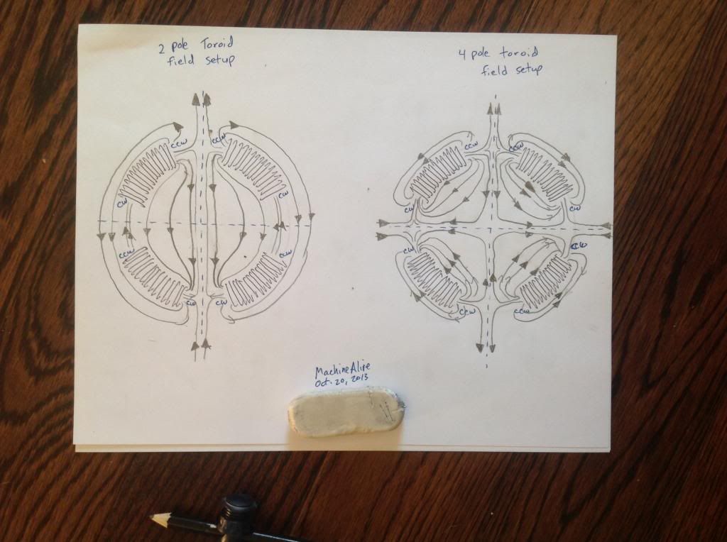
          I do have a model of how I believe we set up fields around the toroid. . This model was not necessary for a spinning drum with energized field coils, but to understand how the toroid could energize the field magnets.
          No stay eddy currents, or leakage magnetism, that can't be contained in ring. There is no action at a distance. And this field should spin big giant motors. And should be set up all around outside of toroid.

          I'll post a vid of how I believe the field coils get set up around the toroid, later today. I'm sure Stupify understands what is going on, he seems to be the only one talking about this?

          Comment


          • About Toroids...

            Originally posted by machinealive View Post
            Hey UFO

            One of my kids woke up last night, and I fell asleep with him. Sorry, I plan on using the dove tails in the stators, put them on any i build.

            Hey John stone, yes I've seen that. Same old, the field is mostly contained in the toroid.

            I do not believe there is appreciable flux around a regular wound toroid to energize stators. Until we wind it right, then we setup real live fields that can turn motors. We just have to spin the toroids fields mechanically, or virtually.

            I do have a model of how I believe we set up fields around the toroid. . This model was not necessary for a spinning drum with energized field coils, but to understand how the toroid could energize the field magnets.
            No stay eddy currents, or leakage magnetism, that can't be contained in ring. There is no action at a distance. And this field should spin big giant motors. And should be set up all around outside of toroid.

            I'll post a vid of how I believe the field coils get set up around the toroid, later today. I'm sure Stupify understands what is going on, he seems to be the only one talking about this?
            Hello Machine,

            I have always observed and seen the Toroid as a great prospect for Generator Purposes basically...We all know that DR Nikola Tesla already used most of its Motoring power to bring Us all the AC Induction Motor.

            But , please...let me add something else...If You desire...you could stop that spinning Egg of Columbus with your hands...meaning, since the Egg mass is being "dragged" the Magnetic Interaction or "Throw Out Forces"...are not that strong like a "Face to Face" Magnetic Field Interaction We all have in our Asymmetric Machines.

            The fact that Toroids keep a high percentage of their magnetic fields contained within its dimensional embodiment...give Us many possibilities to be utilized in the generation of energy fields...

            Think for a minute that the generated field will NOT affect, or other words...it will NOT generate a dragging force, when loads would be connected to their Induced Coils...so, this means that a Toroidal Induced Coil Generator (Even with a Laminated Steel Core Embodiment) would be much better than a "face to face" opposing magnetic fields Structure that will generate the drag we all are so familiar in all the Generators "Available" in the World Market.

            However, I will love to see your idea about making motoring effects with the Toroid...

            About Member Stupify...He has already debunked Tesla's work...and He clearly and fully understand My Asymmetric Machines, and all the possible applications ...He knows it...and I know it...there is no need to start a deep debate about the way DR Nikola Tesla fused Asymmetric Motors with Toroidal Generators and Toroidal Transformers...We both know their working concepts.

            Kind Regards Friend


            Ufopolitics
            Principles for the Development of a Complete Mind: Study the science of art. Study the art of science. Develop your senses- especially learn how to see. Realize that everything connects to everything else.― Leonardo da Vinci

            Comment


            • What do You mean?!

              Originally posted by iankoglin View Post
              G'day UFO
              Thanks for the reply I went and did just did as you said and of course nothing worked

              AS a matter of fact I always tell the truth sometimes
              Hello Kogs,

              What do you mean...when you wrote ..."You did as I told You and nothing worked?!

              Could you be a bit more specific?

              I don't know why I did not remember this as when I modded the small 5 pole I did just that as you had showed and was pleased as everything you said worked exactly.
              I suppose its like the saying goes "If you don't use it you loose it"
              I am sure I will not forget this again
              I did run the motor in reverse i.e. Negative on top and positive on the bottom
              I did not check the speed but I am sure it ran slower.
              Thanks again Pal (Ausie for friend)
              I am going to be very busy with my builds now

              Kindest regards


              Kogs the sun glasses needed the light is too bright
              Did You connect the Input-Output like I wrote previously... in order NOT to create opposing fields...and so Motor should run STRONGER than with just Two Wires?

              Meaning: You have to Input Positive ABOVE and Negative below in TWO set of wires (matching vertical brushes)...Then OPPOSITE Input at what is your Motor Output...OR: Negative above Positive at bottom (lower)...

              Did You do that?

              Let me know what happened?


              Take care friend


              Ufopolitics
              Principles for the Development of a Complete Mind: Study the science of art. Study the art of science. Develop your senses- especially learn how to see. Realize that everything connects to everything else.― Leonardo da Vinci

              Comment


              • Lovely Video!

                Originally posted by warrensk View Post
                Hello all!

                @ iankoglin awesome replication!! I like the size of wire you used, it looks just right! maybe even better than mine!

                Here is a video with the output of my asymmetric motor into a rodin coil that is designed around tesla's equations for resonance....Basically what that means is each primary and secondary winding on the rodin is the same mass of copper...different lengths even turns. I think there is some serious potential for these motors to power things resonantly and wirelessly....The output of the motor in DC is not correlated with whatever is resonating my coil because the higher the DC output, the less my coil resonates....There is a sweet spot at low RPMs...this could be dependent on the PWM running at 13 khz....Or mostly the width of the pulse. I bet if the PWM was at a frequency around 30khz (which is where my rodin coil is resonant at) it would have even better power output....I am putting together an arduino program so I can create my own signals to do just this....This motor output is SOOO much better than trying to pulse it with mosfets....they just keep blowing up when the coil hits resonance!

                Output of Asymmetric Motor into Tesla Style Rodin Coil - YouTube


                Anyways this is an attempt at recreating teslas magnifier setup on a much smaller scale of course, and with a rodin coil instead of a conventional tesla coil....Either way we are definitely onto something!

                Just for clarity, heres the schematic im trying to recreate....Input is a generator, and I think its an asymmetric one...

                http://www.tesla-coil.com/images-new...g-diagram1.jpg

                I have obviously bypassed the step up transformer, but there are other patents in which the generator is directly hooked up to the primary of the tesla coil and he still gets resonance...Let me know what you think!

                -Warrensk

                Hello Warrensk,

                Excellent tests!...Excellent video to show Us all your results...amazing!

                It is very interesting to observe how the square wave becomes an AC Sine-wave when you connect Rodin Coil to Asymmetric Motor Output...but it is even more interesting is to hear how Motor increases speed up...very good!

                The Neon test is also incredible...when you touch it with your fingers...your whole body becomes a source of Radiant Energy...closing the Energy loop and shown in the 120V neon brightness...excellent!

                And I love the sound of that Motor!...very strong and robust!


                Kind regards friend


                Ufopolitics
                Principles for the Development of a Complete Mind: Study the science of art. Study the art of science. Develop your senses- especially learn how to see. Realize that everything connects to everything else.― Leonardo da Vinci

                Comment


                • Hello UFO

                  Hey, I wasn't trying to debate Stupify. Stupify is a smart guy, the only guy that commented about my coils. Stupify has my respect. . Did you think I was debating you Stupify? I hope not.Yea, I believe stupify is gonna get that rotary transformer working.

                  Well, here was my model, I was trying with Figuera. it's all I could come up with.

                  Toroid field setup? - YouTube

                  Comment


                  • Originally posted by Ufopolitics View Post
                    Hello Kogs,

                    What do you mean...when you wrote ..."You did as I told You and nothing worked?!
                    AS a matter of fact I always tell the truth sometimes
                    Could you be a bit more specific?


                    Did You connect the Input-Output like I wrote previously... in order NOT to create opposing fields...and so Motor should run STRONGER than with just Two Wires?

                    Meaning: You have to Input Positive ABOVE and Negative below in TWO set of wires (matching vertical brushes)...Then OPPOSITE Input at what is your Motor Output...OR: Negative above Positive at bottom (lower)...

                    Did You do that?

                    Let me know what happened?


                    Take care friend


                    Ufopolitics
                    G'day UFO
                    You must be very tied as you missed the next line
                    AS a matter of fact I always tell the truth sometimes
                    Which means That I was not telling the truth it was a Joke, sometimes I have to laugh at my own Jokes

                    What I was saying my friend is that it worked Just as you said
                    I was over the moon when I switched it on and it worked first go
                    I did Just as you said and while doing so I remembered that that was what I learned when I wired up the small 5 pole I just missed the point where the Coil say P1 passes the next stator the magnetic field is opposite. there was only 2 stators and I imagined that it was just the field reversing as it left the comm. segment.
                    I am now setting the commutators into my other 250 watt My motor and the 1000w machine and while they are setting I did some various speed and amp draw on the one I have finished wiring I will need to have it balanced and will wait till I have these three motors finished then I will have them Varnished and then Balanced( I am in the process of finding/getting some prices)

                    I will post the measurements when I finish them

                    Like you said You Just have to do it and take measurements and observe what's happening

                    I really appreciate your great expenditure Your Time in helping us all here.

                    Kindest Regards

                    Kogs sees clearly Now

                    Comment


                    • OSH Park

                      Well good news at last on the shipment of my monster drive pcbs. Got an email from Neal today full of apologies and a tracking number for priority mail. Checked the tracking number and the package had indeed shipped. Neal said that the original order had been shipped on 8/29, apparently lost in the mail? Anyway, they have been shipped. Thanks for everyone that got involved, Dana and Sampojo.

                      Cheers

                      Garry

                      Comment


                      • Vishwaroop CAD Diagram...P15

                        Originally posted by ajaya999 View Post
                        Dear Sir,

                        Namaste. Sorry for coming back very late. I was down with ill health for three days. I have been working on Chas Campbell Replica before I approached you for your help in designing my 15-P motor. I didn't want to leave it in between without success. So I continued and yesterday I could successfully replicate Chas Campbell design.

                        I have been going by your videos and writings again and again sir. Every time I am watching or reading, I am finding something new in them and thus advancing myself.

                        I understood you are already overloaded. You already left enough material for understanding and experimenting.

                        I am thinking to take the challenge of designing the winding by myself sir. Today I removed all the armature winding. Let me try sir by myself. If I fail, I will try again. If I fail again I will come back to you sir for your help.

                        Wish me all the best.

                        Regards and Namaste.

                        Kumar

                        p.s.: my son, when he was back from school today -seeing me making a mess with all the cut cables across his room- was asking me "dad ! did you send the photographs to Vishwaroop (he calls you so) uncle? I said I'd EXPERIMENT and send for your help if I fail.
                        Hello Kumar,

                        Thanks for being so kind and so patient!...and hoping/wishing you are feeling better of your health!

                        You are gonna need it to finish this Model...

                        Please find below the CAD Diagram for your P15 Two Wound Stators (I represented like solid magnetic blocks projecting their polarity towards Rotor/Armature, same as I do with permanent magnets...however, after you finish your armature...I will like for you to make more tests that would involve to Pulse those wound stators...

                        [IMG][/IMG]

                        In this Diagram, I am just presenting Pair One (P1), as it gives you more clarity to understand the Timing set up, related to the Start of Firing Brush-Commutator Elements shown in the red group of Four

                        First, Your new Asymmetric Design would have Fifteen Pairs of Coils (P15), where each coil in the pair would be connected in series between them, projecting their polarity as shown (Blue=North, Red=South)

                        Therefore, since your commutators are based on 60 elements each, you will be joining/bridging Four Elements per each Pair (60/15=4) on top and bottom commutators, aligned perfectly vertical in a straight alignment line (like all other Asymmetric Models)

                        Please observe each Coil Bisector Alignment related to Stators Bisectors...and also note the four joint group of commutator elements just STARTING to make contact with brush, according to Rotation "R". This is the strongest Firing-Timing alignment you could get out of this arrangement...maybe a few degrees here or there...that only in practical lab testing would tell you for real...


                        [IMG][/IMG]


                        Now, In this Second Diagram I am showing the other Two Pairs adjacent (right next) to P1...or P2 and P15.

                        According to Rotation "R", P15 is almost loosing contact (to be disconnected) from energizing Input Motor Brushes...to allow P1 to start entering into contact (at this time presented on Diagram, both Pairs, P1 and P15 would be "ON")...While P2 is on "Stand By" ready as "next in line" to establish contact.

                        Please learn to "see" Your Coils bisectors, even if not defined by a line...they all would be the Pole number Three (3), starting count from either side...(center pole of Five Total on Coil)...so, now, look again at P15 and P2 Bisectors NOT painted on this CAD...and relate them to Stators Bisectors Positioning...then you would realize that P2 Bisector is "under" or below from passing the North Stator Bisector, now it is "OFF"...But if it would be energized in this position...it will Counter/Oppose to Rotation "R"...taking away from Machine Torque and Speed.

                        On the contrary...P15 Bisector is passed beyond P1 Bisector...so this means P15 would be "assisting" P1 in favor of Rotation "R".

                        This Three Pairs together...will give you a better understanding of "Close and Start of your Pairs" in the total winding sequence... as also the Four Elements positioning-connected on Commutator for each related Pair.

                        Your new Asymmetric Motor would be a very strong and very fast Machine (much more than it was in Symmetric Winding)...and also would give you a great Output, since always more than one Pair would be connected to the Generator Brushes at 180º apart...

                        Your Motor type is categorized within the "Universal Motor Configuration"...and that means...that your nice looking Asymmetric Machine...would operate with AC and DC Currents...giving all of Us very interesting results with each different type of electric feed...

                        All I ask you in return...is to keep posting here your progress, for all of Us to enjoy...as, if possible...some pictures of your model.

                        Or else I would have to ask your son for the Pictures......Tell Him the Vishwaroop already send you the Diagram...so now is all in your hands to make it happen...

                        Kumar, you will be building a very interesting machine...and like I wrote before...please, do not touch your Stators windings!!...leave them just like they are now, just transform-modify your Armature/Rotor into Asymmetrical Type...but not the Stators (for now)...

                        Later on You could perform different types of Connections between Stators and Brushes...like Series between Stator/Motor...or Parallel...as you could also assist feeding to Stayors from Machine Output side...and so on and on...but finish rotor first...


                        Kind regards , Namaste


                        Ufopolitics
                        Last edited by Ufopolitics; 10-20-2013, 04:54 PM.
                        Principles for the Development of a Complete Mind: Study the science of art. Study the art of science. Develop your senses- especially learn how to see. Realize that everything connects to everything else.― Leonardo da Vinci

                        Comment


                        • toroid setup

                          ok...no comments...its been awhile. Ya still chewing, or did you swallow yet UFO.

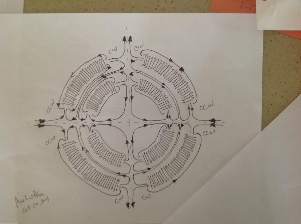
                          I threw the fields on pretty quick last time, in the vid, here is a better drawing, sure would look nice in 3d ufo. Reminds me of atomic orbitals.

                          Comment


                          • Comrades

                            Lets fill the next Orbitals. Think I could build a magnetic bearing?
                            The "MFB".. Looks a lot like an antennae also.

                            They threw us off the trail, with a spinning egg (with no torque).

                            But WE are TOO Smart for them. WE spin a shaft instead of an egg.

                            Comment


                            • Makes sense to me...

                              Originally posted by machinealive View Post
                              ok...no comments...its been awhile. Ya still chewing, or did you swallow yet UFO.

                              I threw the fields on pretty quick last time, in the vid, here is a better drawing, sure would look nice in 3d ufo. Reminds me of atomic orbitals.

                              Hey Machine,

                              I do agree with you...in the video shows it clear...and now this is better explanation of the flow...it makes sense...however, induction is sometimes "unpredictable"...even though it makes perfect sense in Theory it may turn out it does not work as "expected"...so...

                              The only way to find out...is to test all options.

                              Once you've got the Drum structure running, easy in-easy out dismantling...it would be a piece of cake.

                              Now related to building Drum out of Laminations...what are your thoughts?

                              I believe once you have them stacked/aligned and pressed together...it would be a very solid structure, even being very thin thickness at wire core ring section.

                              I was also thinking about adding fins like you have mentioned as to create/force a path for wires...but then making it "angled" like ///// instead of "radial" like lllllll we are figuring/drawing it now.

                              I have been working in a better design for the Dual Rotors configuration...in order that expanding an existing motor rotor structure would not be that hard , clever and expensive to make...and I believe I've got it...


                              Regards


                              Ufopolitics
                              Principles for the Development of a Complete Mind: Study the science of art. Study the art of science. Develop your senses- especially learn how to see. Realize that everything connects to everything else.― Leonardo da Vinci

                              Comment


                              • Agree..

                                Originally posted by SERG V.
                                Hi Ufopolitics

                                Use insulated steel wire instead of copper for stronger magnetic field {or any wire with higer specific resistance}.

                                But don't belive me check yourself and see. Take two wire one from copper other for example nichrom with much higher specific resistance. Make two identical coils and give each coil same current density. For example 10Amps/cm2. Use compas to find maximum of B-field. Than measure B-field with Tesla meter and control current with Oscillograph. Nichrom coil will give you stronger field. Why ?? Because something is wrong with the law of Bio-Savar-Laplase !!

                                What will be if you put your coils at super conductivity temperatures and give them current density in range 1e5-1e6 Amps/cm2 {or bigger}. How stong will be B-filed ? Or there will not be B-filed at all ??
                                Experiment will tell you all you need !!

                                I told you a simplest way to rise up COP in your motors.

                                Btw would you like to see UFO scout ship which belong to agressive hermaphrodite race of Grays - servants of Princes of Darkness -Koscheys.
                                All their UFOs use cloacking technology. Especially love to surf around Nuclear Missiles Launch sites and Nuke power plants. They glue their mind especially on Uranium and Plutonium "food". Btw NASA still cabal and brainwashing people minds with Faerie-Tales.


                                Удачи всех благ !!
                                Сергей В.

                                "Spasiva" Serg V!

                                Definitively a test We all should make...and I would definitively do!...have to find the wire source...

                                I also have been thinking about the Teflon Wire that Ed Gray used on his Motors...

                                The other Test that I want to do...(but this one is harder, 'cause it does not exist that I know off)...is Insulated and Stranded Carbon Fibers as "magnetic wire"...


                                Many thanks and Regards


                                Ufopolitics
                                Last edited by Ufopolitics; 10-20-2013, 01:18 PM.
                                Principles for the Development of a Complete Mind: Study the science of art. Study the art of science. Develop your senses- especially learn how to see. Realize that everything connects to everything else.― Leonardo da Vinci

                                Comment

                                Working...
                                X