Announcement

Collapse
No announcement yet.

My Asymmetric Electrodynamic Machines

Collapse
X
 
  • Filter
  • Time
  • Show
Clear All
new posts

  • Re: Ufo post 5826 Boldor 20 Pole winding ideas

    Originally posted by Ufopolitics P195 #5826 View Post
    Hello Sam,
    ...
    It is simple...if you want to load with copper the rotor...then just make a P20 to work with Two Stators...and Aim the center of the Pair or "< " to fire right at Dead Center of either one of the stators, (That would be Your "Neutral Point") having in mind that running above towards one side will generate a rotation that same way...as also depends upon the setting of each Coil in the Pair.
    Multo grazie Ufo!

    OK, more strong eh? good, hoping I can get enough energy to get over the hump... I am thinking about grabbing the last motor over at my motor goldmine there, but it has an apparatus of some sort attached and they want twice as much for it. who knows, maybe order some extra brush pairs from the electric motor company for me and convert one of these to a 4 stator some day in the near future. Dreams of concatenating motor bodies and rotors and ordering a double long shaft at a machine shop... and my imagination runs away ....

    I am going to guess on where you are saying the brushes go. How's this?
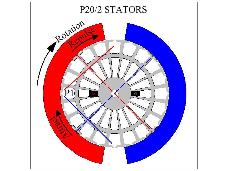

    So I was planning to use as much wire as came off the symm rotor on these Baldors, since they were stuffed. I figured to put about 130' of quad filar at 2.5ohm per coil in the 5-pole designs, but started having my doubts about leaving the space in between subtended poles and getting as much wire. Now assuming I can get as much wire as the orig with this approach, it seems to me I will be dealing with 20 coils now, each one is likely to have .6ohms.

    Ufo, would you say that I should try to go higher resistance per coil now with 20 coil pairs?

    If I now go to trifilar 30g, that would probably raise it to 1-1.5ohms. It would be like jumping the single strand original 19ga. to up to maybe 22ga. or even higher since it would be trifilar 30ga. need to look at it.

    FYI stators in diagram pretty close match to the Baldor

    Sam
    Last edited by sampojo; 12-29-2013, 04:07 PM.
    Up, Up and Away

    Comment


    • NEED HELP,which motor would be best to rewire for my needs which are 1000-1500 rpms MAX and need MAX torque(not rpms) ... i am just going to put straight current into it. which motor and which pattern would be best to rewire? are there any pdf files i can download and print so its easier then looking at laptop in the dirty shop? if anyone has one already built and willing to sell to me would be best option .THANKS

      Comment


      • Originally posted by sampojo View Post
        Multo grazie Ufo!

        OK, more strong eh? good, hoping I can get enough energy to get over the hump... I am thinking about grabbing the last motor over at my motor goldmine there, but it has an apparatus of some sort attached and they want twice as much for it. who knows, maybe order some extra brush pairs from the electric motor company for me and convert one of these to a 4 stator some day in the near future. Dreams of concatenating motor bodies and rotors and ordering a double long shaft at a machine shop... and my imagination runs away ....
        Hello Sam!

        Prego (You are welcome)

        I am going to guess on where you are saying the brushes go. How's this?
        Positioning on brushes are relative, you could use their original positioning, if it was other than shown on diagram...the key is to start running the first pair (P1) WIRES to make contact wherever they be...

        So I was planning to use as much wire as came off the symm rotor on these Baldors, since they were stuffed. I figured to put about 130' of quad filar at 2.5ohm per coil in the 5-pole designs, but started having my doubts about leaving the space in between subtended poles and getting as much wire. Now assuming I can get as much wire as the orig with this approach, it seems to me I will be dealing with 20 coils now, each one is likely to have .6ohms.
        Correction: You will be using Twenty Pairs...meaning 40 Coils, twenty North, Twenty South...

        Ufo, would you say that I should try to go higher resistance per coil now with 20 coil pairs?

        If I now go to trifilar 30g, that would probably raise it to 1-1.5ohms. It would be like jumping the single strand original 19ga. to up to maybe 22ga. or even higher since it would be trifilar 30ga. need to look at it.

        FYI stators in diagram pretty close match to the Baldor

        Sam
        The rule is simple Sam, the more number of Pairs running on Armature...the less resistance you could afford to use per pair...since the timing ON per Pair would be much less than just Five Pairs. So I would use here a higher awg wire, for much stronger fields per nano second, fast rising, less resistance...say awg 22 Bifilar, 20 or even 18 single strand... example...

        The winding is identical to a P20 Four Stators...the only difference is that each Pair would be interacting with just One Stator, with Dual actions (attract/Repulse) as also the opposite pair at 180º (Output)...normally in a 4 Stator each Coil in the Pair have One Stator to interact with...so it is 2S per Pair...and each coil would be making "single action", meaning, all four repulse...or all four attract.


        Regards


        Ufopolitics

        EDIT 1: Just for the records, and as an example...I used 18 awg on my BOSCH 20 Poles Four Stators...around twenty turns (20T) per Coil, it runs great torque but slower on 12V...but excellent on 24V and above.
        Last edited by Ufopolitics; 11-13-2013, 01:15 PM.
        Principles for the Development of a Complete Mind: Study the science of art. Study the art of science. Develop your senses- especially learn how to see. Realize that everything connects to everything else.― Leonardo da Vinci

        Comment


        • Original drum winding design

          Hi all,

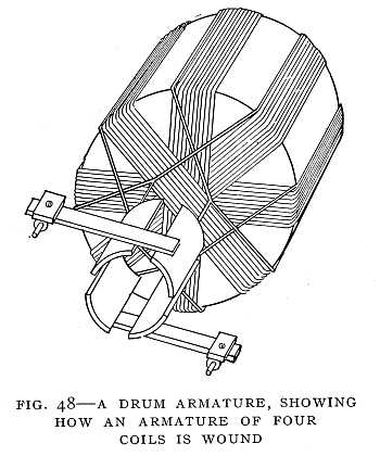
          Please note the differences between the original design of a drum winding (done by Hefner-Alteneck around 1870s) and the current drum winding design. The original drum winding design is the one that Figuera used in his rotary drum generator.


          As you can see, originally the design was a "diametrical" winding !!

          The Drum Armature

          An improvement in the Siemens armature was made four years later by Von Hefner-Alteneck, an engineer in the employ of Siemens. This improvement consisted in winding on the iron core a number of coils similar to the one coil of the Siemens armature, but wound in different directions. This is called the "drum armature" (Fig. 48). The heating of the core is prevented by building it up of a number of thin iron plates insulated from one another and by air-spaces within the core. The insulation prevents the small currents from flowing around in the core. The air-spaces serve for cooling. The drum armature was a great improvement over both the Siemens and the Gramme armatures. With the Siemens one-coil armature there is a point in each revolution at which there is no current. The current, therefore, varies during each revolution of the armature from zero to full strength. In the Gramme armature only half the wire, the part on the outside of the ring, receives the full effect of the magnetic field. The inner half is practically useless, except to carry the current which is generated in the outer half. Both these difficulties are avoided in the drum armature
          1911 Encyclopædia Britannica/Dynamo - Wikisource, the free online library

          The electrical engineer (1890)


          Regards
          https://figueragenerator.wordpress.com/

          Comment


          • Originally posted by hanon1492 View Post
            Hi all,

            Please note the differences between the original design of a drum winding (done by Hefner-Alteneck around 1870s) and the current drum winding design. The original drum winding design is the one that Figuera used in his rotary drum generator.


            As you can see, originally the design was a "diametrical" winding !!


            1911 Encyclopædia Britannica/Dynamo - Wikisource, the free online library

            The electrical engineer (1890)


            Regards


            you can see it described here as well :

            The Tesla System of Distribution and Electric Motors for Alternating Currents from The Electrical Engineer, May 25th, 1888

            and here :

            A New System of Alternate Current Motors and Transformers from The Electrical Engineer, June 15th, 1888

            In the first experiment a drum-armature was provided with two coils at right angles to each other, and the ends of these coils were connected to two pairs of insulated contact rings as usual. A ring was then made of thin insulated plates of sheet iron, and wound with four coils, each two opposite coils being connected together so as to produce free poles on diametrically opposite sides of the ring. The remaining free ends of the coils were then connected to the contact rings of the generator armature so as to form two independent circuits, as indicated in Fig. 9
            Last edited by MonsieurM; 11-14-2013, 01:08 AM.
            Signs and symbols rule the world, not words nor laws.” -Confucius.

            Comment


            • Re: esesenergy request for info

              Hi eses,

              Originally posted by esesenergy View Post
              NEED HELP,which motor would be best to rewire for my needs which are 1000-1500 rpms MAX and need MAX torque(not rpms) ... i am just going to put straight current into it. which motor and which pattern would be best to rewire? are there any pdf files i can download and print so its easier then looking at laptop in the dirty shop? if anyone has one already built and willing to sell to me would be best option .THANKS
              Got a big ten-pole laying around? Ufo says this has low rpm hi torque performance:

              Originally posted by Ufopolitics P33 post 972 View Post
              Hello to All,

              Here is the Asymmetrical Dual Pentagons, this Motor fits all 10 and divisible of 5 Armatures...like 20 Poles with Quad Pentagons.
              This Motors at 10 Poles shown here, have incredible torque with very low voltages, however due to short Throw Out Angles by just Two Poles Coils, they do not deliver High Speeds.

              They are great for lifting applications where heavy force is required, like Hydraulic Pumps, Robotic Servos and Mechanical Driven Mechanisms, like Automotive windows regulators.

              In the 20 Poles Structure, is understood it could be arranged for speed also, by winding Four Poles per Coil, magnifying its "Take Off/Throw Out Angles" at Magnetic Interactions. Or could be dedicated to even more Torque, than the 10 Poles here, by adding Four Pentagons at Two Poles instead.


              [IMG][/IMG]

              I have built this type in several configurations, that ranges from Hydraulic Pumps to the Sullivan Gas R/C Starters...They are more expensive than the Chinese, but worth it, they are American Made, and very well built ...not like the TorqMaster , they come in several Models, High to Low prices...Higher is the Dyna-Tron Model, then I got the cheaper one for parts...

              Now there is one particular issue here, their shaft is thicker front, finer in rear...so there are Mod's to be done there, The easy way out is by using the Cap from front of other Motor then adapting the great Brass bushings casing/Mica boards that will have to be press into the Aluminum Housing pre fab built in rivets, that will fit great...

              The Outer Frame does have to be Lathe-Cut - Mig Welded to Extrude it...is heavy steel Tubing. Or You guys could just use matching Aluminum Tubing Spec's (ID) and cut to size...

              Brushes are set at around 30 Degrees from Stators ending opposed corners...But I made some grooves to be able to adjust them...

              That is the Motor on this Video:

              TEST TWO, OPPOSED PENTAGON WIRING DESIGN, SULLIVAN MOTORS - YouTube

              The Heavy Torque is "delivered" entirely by Radiant (C)... (Can't EVER Copyright HER...SHE is Free Now!!)

              If You notice in Diagram, while N1(Blue)-S1(Red) are at Input being Energized, N3 (Cyan)-S3(Rose) and also N4(Green)-S4(Yellow) are completely assisting Rotation(Remember Radiant Flows Opposite, therefore Magnetic Poles are reversed from Diagram...IF they will not reverse...Motor will NEVER turn half mm..)...so, it is actually Two Pairs acting from Radiant, while we just "spent" a small energy activating One Pair...

              The best way to measure a closer Input this Motors are taking, is by Pulsing them...


              Regards


              Ufopolitcs
              Ufo built it, not a small size, maybe he will sell it to you Really looks loaded for bear for low-end torque!!
              Up, Up and Away

              Comment


              • Re Ufo post 5818 Tesla's ways ... Our ways

                Slightly condensed...

                Originally posted by Ufopolitics P194 post 5818 View Post

                We conceive Induction By Face to Face Both Magnetic Fields...The Exciting and the Induced Fields...and according to the exact Law from Lenz...they are of OPPOSITE NATURE...so, what isn't more convenient....than to face to face a North and a South in a perfectly designed 180º?!...This way...the more we demand loads from the Generator...the STIFFER it will get...right?...so what do we all do now?...of course our closed loop/short circuit Motors...burning more than what they can render...just can't "Prime Move".

                [IMG][/IMG]

                Tesla winds the Induced Coils in a "Diametrical" Fashion...why?...in order to get the Induced Fields NOT TO BE FACING the Exciting Fields...Therefore...instead of opposing and dragging Rotation forces....they will ASSIST...Vualá!!

                Nikola Tesla also utilizes the TOROIDAL Geometry in order NOT to Face to Face Both Fields...

                Then they tell Us...that "Tesla stuff was obsolete"...that "it did not work"...but worst than worst...we ALL believe this crap...this Scam...This Conspiracy to get Oil Primarily as a Main Source of Energy in the "Prime Mover Industry".


                I believe I've made all this Graphics as easy to understand as I possibly could, even for those not that expert in Electromagnetism...so I hope You All "got this" now...

                Ufopolitics
                So drum/diameter winding setting things 90 degrees off is superior to even asymmetric axial winding ??? If so how do we get started?

                dieing to know, Sampojo
                Up, Up and Away

                Comment


                • Induction advantage...

                  Originally posted by sampojo View Post
                  Slightly condensed...


                  So drum/diameter winding setting things 90 degrees off is superior to even asymmetric axial winding ??? If so how do we get started?

                  dieing to know, Sampojo
                  Hey Sam,

                  This is about Induction mainly...showing the advantages to keep both fields away from each others could reduce considerably magnetic drag...it is understood that for Stronger Motor action is better the "Face 2 Face" approach...

                  Regards


                  Ufopolitics
                  Principles for the Development of a Complete Mind: Study the science of art. Study the art of science. Develop your senses- especially learn how to see. Realize that everything connects to everything else.― Leonardo da Vinci

                  Comment


                  • Makita's Four Pole Design...

                    Hello to All,

                    It caught my attention a new Power Drill available from Makita only (Let me guess it is a "Patent Issue"...)...advertising it as a "Four Pole Design Motor"...

                    [IMG][/IMG]

                    Then I found this awesome comparison between a similar De Walt (but a 2 Pole) and the Makita Four Pole:

                    THE NEW MAKITA BHP454 vs. THE NEW DEWALT DCD950 - DeWALT Owners Group - Forum for Dewalt owners

                    They are referring to Four Stator Configuration Motor...with a Ten Teeth Rotor (We call them Poles)...:

                    [IMG][/IMG]

                    Makita uses very compacted Four Neo's Stators, housed into a nice laminated steel frame.

                    [IMG][/IMG]

                    However, Makita is using Two Brush System...

                    [IMG][/IMG]

                    If You notice, brushes are NOT set at 180º apart like a typical Symmetric System Design...This creates an Asymmetrical Plane of Interactions, where a very wide angle, I would say around 90X3=270º...would be interacting with about Three Stators...while just 90º (closing brush "V" Angle) would be doing the other side of opposite magnetic field with just one stator width. This creates a huge Asymmetrical "Unbalance" of Magnetic Forces, delivering better Torque than a Two Pole System with 180º Symmetrical Plane delimited by the Brush positioning.

                    However, I have tested this Makita Drill...and IMO, honestly, nothing that "Impressive" as Torque or Speed...as it is still "assisted" by a very Complex Gear Box to Chuck end...still, it is a very expensive Power Drill ($99.00 USD) without Battery...

                    I thought bringing this "New" Design here was interesting...since We could also make this kind of arrangement with our Asymmetrical Machines...referring to the combination of Four Stators with Only Two Brush set...

                    By utilizing Four Stators, we are "shortening" therefore "compacting" each interaction per Coil, and not using the whole Stator to do both Coils in the Pair...for example I will cite Sampojo's Motor he is constructing as going for the P20 Asymmetric Design:

                    [IMG][/IMG]

                    Then, same P20 but, with Four Stators:

                    [IMG][/IMG]

                    What We have is -like I said before- a more compact/independent interaction for EACH COIL in the Pair, since each coil would have a Stator to Interact with. The "draw back" here is...Radiant Energy manifesting around P6-P15...then transmitting its Counter Force to directly set Pairs P1 and P10 (accordingly to rotation sense)...So We will need to kill Radiant by injecting P1 and P10 Brushes with same directional voltage and NOT in opposite configuration like we have seen before for two brush systems...so, no output then...

                    So, how could we collect Radiant or Reversed Output with just two brushes?...

                    Simple...We Connect Opposed Pairs at 180º like P1 and P10 either in parallel or series (depending upon our resistance per pair) to be utilizing Only One End of Commutation Elements...and for this, then we will need to reduce the number of elements to half of the typical P20-20 Comm Elements to a P20-10 Comm Elements Ratio.

                    In the case of the Makita 10 Rotor Pole, Four Stators, we could use a P10, with just five comm elements (joining each two), in order to feed Two Pairs with just one Brush above one below.

                    I just wanted to share this possibility...in order to show the flexibility and allowance to exchange designs in Asymmetrical Systems.


                    Regards to All


                    Ufopolitics
                    Last edited by Ufopolitics; 11-16-2013, 04:30 PM.
                    Principles for the Development of a Complete Mind: Study the science of art. Study the art of science. Develop your senses- especially learn how to see. Realize that everything connects to everything else.― Leonardo da Vinci

                    Comment


                    • Asymmetric, Attract Versus Repulse Modes...and Amp draw.

                      Hello again,

                      Since the above post "touches" the Repulsion Timing/Firing We all have been using, basically at Imperial...I wanted to share some new findings on this two ways to achieve rotation.

                      We all know we could set our Machines to work based on repulsion mode, firing Coils in the Pairs as close as possible to Stators Bisectors...like I showed above:

                      [IMG][/IMG]

                      I have to admit, I been encouraging all to use this approach, because of the incredible higher Force and Speed Machine develops from the very start...which is true, and everyone has test them...however, by working on a specific drill model...I have been tuning the timing by rotating stators magnets since brushes are fixed...and feeding motor with a Power Source Unit...in order to measure V and A ratios.

                      The Conclusion was the following:

                      By using the "Attract" Approach like below:

                      [IMG][/IMG]

                      I reduced the Amp Draw from over two amps...to around 1.30 to 1.20 Amps by just rotating magnets to work more on attract mode...

                      The sacrifice, by doing this...lies on the starting Torque not being as robust from the very first second of operation, like we all obtain in Repulsion Mode ...but increasing gradually to reach the force in a "smooth" curve through time...

                      So, it is good to know this...as it serves to the application we would be using our machines for...In the case of my Drill Motor...it would be fine, since motor would be attached to the same Gear Box as the Symmetric Model, which does the same "smooth" start, but never drops the amp draw like my Asymmetric Model does...

                      I encourage You to make this tests and verify what I am relating to, above.


                      Regards to all


                      Ufopolitics
                      Principles for the Development of a Complete Mind: Study the science of art. Study the art of science. Develop your senses- especially learn how to see. Realize that everything connects to everything else.― Leonardo da Vinci

                      Comment


                      • For Midaz only...

                        Hello Midaz!

                        Wonder how the Bike and Motor are coming along?!

                        While doing some research on Electric Bikes... and EV'S in general...I found a very interesting pdf related to a "Super E-Bike" for the TT Isle of Man Racing:

                        www.electricmotion.org

                        On Right Column Links go to "Building eSuperbike and the Isle of Man TT Zero"...then at the bottom is the pdf:
                        "LennonRodgers_EVS_Paper_2012_Final.pdf"

                        Save it...I believe it has great info as main design and layout.

                        Even though it has absolutely no comparison with your Imperial Beast...or our Monster Pulsers Design...but, there are some balancing and set up that I believe are interesting to know...

                        The site seems like a bit abandoned...can't see single detail pictures, links don't work,etc...and the Bike the guy built (not the eSuperbike, but the one on main page) is a typical Symmetrical failure...as spec's in speed and range...


                        Regards


                        Ufopolitics
                        Principles for the Development of a Complete Mind: Study the science of art. Study the art of science. Develop your senses- especially learn how to see. Realize that everything connects to everything else.― Leonardo da Vinci

                        Comment


                        • Getting good!

                          Originally posted by Ufopolitics View Post
                          Hello Midaz!

                          Wonder how the Bike and Motor are coming along?!

                          While doing some research on Electric Bikes... and EV'S in general...I found a very interesting pdf related to a "Super E-Bike" for the TT Isle of Man Racing:

                          www.electricmotion.org

                          On Right Column Links go to "Building eSuperbike and the Isle of Man TT Zero"...then at the bottom is the pdf:
                          "LennonRodgers_EVS_Paper_2012_Final.pdf"

                          Save it...I believe it has great info as main design and layout.

                          Even though it has absolutely no comparison with your Imperial Beast...or our Monster Pulsers Design...but, there are some balancing and set up that I believe are interesting to know...

                          The site seems like a bit abandoned...can't see single detail pictures, links don't work,etc...and the Bike the guy built (not the eSuperbike, but the one on main page) is a typical Symmetrical failure...as spec's in speed and range...


                          Regards


                          Ufopolitics
                          UFO and team

                          That was a good project at the time. The bikes that were/are using the twin Agni motors are giving up. They just can't compete with the newer motor designs in performance. Plus the amount of money needed to redesign a new bike is putting the old OFF THE SHELF racers out of competition.

                          As far as our bike, thing are moving slow but steady. I went to see one of Japan's most respected CHEIF Electric Motor Engineers last Wednesday ... He had never seen a two commutator motor. He wanted to know the difference between a series wound dc motor and ours. I told him to imagine an electron "Highway" and the electrons traveling at full speed oneway from one commutator to the other, that our system is an open ended system. DC Series Wound motors are a closed looped system. He is very interested in our system... I told him I needed some small supplies; Nomex paper, acrylic fiberglass, wire, etc.. They sent me a small package this morning. After lunch I will complete Radiance and do some test.

                          Time for lunch

                          Keep it Clean and Green
                          Midaz

                          Comment


                          • Radiance is running smooth

                            UFO and Team

                            Put the acrylic hedges on and made some adjustments. Spun her up at 12volts. She is smooth and almost no sparking at the comms. The rpm sound like its in normal range and the torque is strong.


                            Keep it Clean and Green
                            Midaz
                            Last edited by Midaztouch; 11-17-2013, 01:49 PM.

                            Comment


                            • Burning Sneakers Test 1...

                              Originally posted by Midaztouch View Post
                              UFO and Team

                              Put the acrylic hedges on and made some adjustments. Spun her up at 12volts. She is smooth and almost no sparking at the comms. The rpm sound like its in normal range and the torque is strong.


                              Keep it Clean and Green
                              Midaz
                              Hey Midaz!

                              Thanks for video update! She definitively sounds good!

                              Now, too quick to see on video, but I believe you are feeding all Four Gates?!

                              I see like three or four black cables to Batt Neg and definitively Four Red to Batt Positive...

                              If you feed all gates at once,including the Output side, you are not allowing much time off for Idling Coils, NOT allowing Radiant to enter the system to assist, as you will be drawing too much amps...plus tending to brake/stop/slow motor.

                              So, please, I recommend to run a test first by just feeding Gates P1-P15 (Opposed by 180º) with 12V Fully charged Battery, and lay cables cleaner so we could see them better.

                              Leave the Output Gates completely Open, no connection...on second test you could add a DMM Out, measuring Volts Out in series both Gates could be.

                              Sparking is low, that's great!


                              Regards


                              Ufopolitics
                              Principles for the Development of a Complete Mind: Study the science of art. Study the art of science. Develop your senses- especially learn how to see. Realize that everything connects to everything else.― Leonardo da Vinci

                              Comment


                              • Originally posted by Ufopolitics View Post
                                Hey Midaz!

                                Thanks for video update! She definitively sounds good!

                                Now, too quick to see on video, but I believe you are feeding all Four Gates?!

                                I see like three or four black cables to Batt Neg and definitively Four Red to Batt Positive...

                                If you feed all gates at once,including the Output side, you are not allowing much time off for Idling Coils, NOT allowing Radiant to enter the system to assist, as you will be drawing too much amps...plus tending to brake/stop/slow motor.

                                So, please, I recommend to run a test first by just feeding Gates P1-P15 (Opposed by 180º) with 12V Fully charged Battery, and lay cables cleaner so we could see them better.

                                Leave the Output Gates completely Open, no connection...on second test you could add a DMM Out, measuring Volts Out in series both Gates could be.

                                Sparking is low, that's great!


                                Regards


                                Ufopolitics
                                UFO,

                                I can't wait to burn some rubber. So, my sneakers had to do!
                                Yes, all 4 gates were together. I will energize p1 & p15 next time.

                                Midaz

                                Comment

                                Working...
                                X