Announcement

Collapse
No announcement yet.

My Asymmetric Electrodynamic Machines

Collapse
X
 
  • Filter
  • Time
  • Show
Clear All
new posts

  • Originally posted by GChilders View Post
    @UFO and the Star Team

    Here's to breaking barriers and achieving what others might deem impossible, good luck to all working on the projects.

    @Kogs

    That is a beautiful build my friend, I loved the pictures. Are those scooters direct drive or are they going to go through a gear box and then to the rear sprocket?? I have been thinking that gas powered motorcycles and automobiles have gear boxes because they don't have the torque that is needed to get them up to speed quickly. Electric motors have lots of torque for their relative weight. But would it save on the charge life of the batteries if they had a gear box? Just thinking ahead to a few projects that I have in mind.

    Cheers

    Garry
    G'day Garry, et al
    Thanks for the comment

    I am going to build my own Tricycle it will be made of Plywood
    and have 3- 22" Bicycle wheels with double rims I still have to design it yet, it will be driven by the 1000W motor using 24v probably there will be an 11 tooth sprocket on the motor driving a 60 tooth? sprocket fitted onto a 3/4" shaft with a differential probable as shown here


    My engineer friend who does all my metal turning said he probably has one from an old Mower or something that he pulled apart some time ago I will be seeing him on Thurs or Friday to look for it in his shed if not I will buy the one above US4145.44 delivered to me in Aus.

    I find I am getting better now at winding the motors

    I might have to rewire my smaller motors

    I finished putting my motor together today and it seems to run very smooth using first 12v then 24v even though it appears to be about 8grams out of balance I was not able to get the speed as yet

    Perhaps I will not need to Varnish or balance it


    The motor I left the wiring to the Brushes as per original that is there is 4 pairs of brushes i.e. 4 on the top and matching 4 on the bottom it is connected to the battery via 2 pair parallel motor Brushes and 2 pair parallel Generator brushes.
    I used a battery box that shows the amps drawn from it

    I did some preliminary tests on the motor and the results were running 24v

    1. 1 pair only motor poles Draw = 1Amp the yellow DMS shows the pair GP=24v

    2. Feeding the GP back into the motor Draw =390ma

    3.Using the Monster Driver MP= 1 Amp GP=19.5v

    4. 1pair only MP draw =600ma with GP fed back into motor

    I took some pics with my IPad they are here

    First Trial Run Photos by Kogs1 | Photobucket

    I really want to use the Arduino to run this motor But I have to find out how to connect it up

    I will keep you all posted as I progress

    Kindest Regards


    Kogs slowly progressing

    Comment


    • happy new year

      hi everyone,

      in india we are already into 2014.

      happy new year to everyone, hope this new year will bring in joy for us by winning over the petro-cartel and governments like spain.

      kumar
      india

      Comment


      • Back to work gentlemen

        @ UFO, Team & Kogs

        Happyyy Newww Yearrr!!!

        It's great to begin a whole new year! The next step for me is to source lithium batteries. I've looked at a lot of battery brands and companies. It looks as though I've found a winner. I'm looking at two sets of 48v x 30amps or 40amps. The company is G.E.B. Our agent is Danni. She is funny and hard working. She will get us what we need for lithium batteries! Unless you've found something better, here is what I'm looking at. Gebattery|LiFePO4|LiFePO4 battery|Polymer lithium battery|lithium-Cells|LiFePO4 18650|26650|power battery|Electrically bicycle battery|Electrically motorcycle battery-Product Center,
        Let's have a stellar year!

        Keep it Clean and Green

        Midaz

        Comment


        • Originally posted by ajaya999 View Post
          Dear Sir,

          Namaste. Sorry for coming back to you very late. I did the rewinding almost 2 months back. but couldn't manage to come to you as i continued experimenting with it.
          I started winding between pole 1 and pole 15 going right passing 15,14,13,12 and 11 clockwise. I took 20 turns of 23 SWG. Once the 20 turns were completed i took it anti clockwise from pole 1,2,3,4, and 5( here i did wrong. this is not as you suggested sir. you suggested 2,3,4,5 and 6). So my clockwise winding went as you suggested, but anticlockwise winding started one pole earlier and closed one pole earlier, though it covered 5 poles.

          I mistook brush positioning also while giving you the specs. Foolishly I counted only one pole of stator( not axis) and mentioned they are 180 degree to stator poles. but they are 90 degree to stator pole axis. Sorry for this mistake sir.

          My stator coil mfg specs are 230V and .4 Amp

          Armature coils Mfg Specs 230V and 4 Amp

          I bought a DC drive to run this motor.

          After winding the armature ( sorry MY MISTAKE, not as suggested by you as i forwarded my winding by one pole on anticlockwise winding),I powered the stator coil from the drive i bought and i conneted brushes to 12V 7.5Amph battery. It RAN sir . It ran with about 120 rpm, though the torque was not good.

          (Before this winding, i did the winding without keeping paper, out of anxiety to wind it quick, to protect it from shorting and all winding burnt out )

          But when i tried to connect the drive to the armature, the winding atarted burning.

          Regarding the original armture winding, it came with 300 turns (15 coils - each coil 20 turns) 23 SWG, but all connected in series. I didn't check the Resistance of it sir.

          Then I bought a used .5 hp ac motor and coupled this 1 hp redesigned(though wrongly ) DC motor. When the stator was powered, the RPM was not getting effected. the voltage was coming, but not usable.

          I did a very mature video shoot of it. It came for 5 min and 7 min. but delivering not that quality information.

          But now i learned how to present it in videos as well sir.

          And now I can make a DC motor sir( though can't Design).

          Any difficult winding for others is not so to me

          Dear sir, please guide me and i will not miss this time every minute detail.

          I'm attaching the link of my uploaded photos here. Every photo is titled with serial number and detail of it.

          ajaya999's's Library | Photobucket

          here are my amature video links
          1 - YouTube
          2 - YouTube

          Promise I'll improve the content quality of my videos sir hereafter

          A very happy new year to you sir and to every one here.

          Thanks and Namaste

          Kumar
          Hello Kumar and Hello to All, and Happy New 2014!

          Well, I must say about the videos you have a Heck of a "Camera Man" assisting You there...and letting your hands dedicate exclusively to work on your device(s)...I wish I had such a great assistant!...

          Now, First, You should decide whether you want this Asymmetrical Machine as a Generator or as a Motor. They have different set up as coils arrangement and brushes positioning.

          You must realize that in a Motor we are looking for the shortest Interactions in the sweeping Time while coils are Energized or "On"

          In a Generator Mode occurs a completely different process, We are looking for Longest Sweep Times (In order to collect the most of Energy) when Coils are Induced because of passing/cutting through the Stators Magnetic Fields lines of force.

          Therefore, it is important that you decide which way you want to go. Even though it just requires a few changes in the connections related to Brush and Coils Positioning...for example:

          [IMG][/IMG]

          Above is the way I have oriented you to set up your Motor first, and that is in Repulse Mode.

          But You could also set it to run on Attract Mode (Less Amp Draw) like shown below:

          [IMG][/IMG]

          On Attract Mode, one thing to have in mind is to ALWAYS Keep the Alpha (Green Angle) Greater than the Theta Angle (Yellow) defined by the Comm Elements attached to that particular Pair of Coils. This is to avoid Rotor Coils and Stator Coils to lock-up, because of reaching face to face bisectors while still on...so, by keeping the brush always smaller angle will disconnect before reaching this stage.

          So then, in Generator Mode Your Machine will look like this:

          [IMG][/IMG]

          Now, If you try to energize (feed) this Brushes and expect Machine to turn...it will NOT happen, it will just vibrate, because if notice Bisectors are locked-in, related to stators positioning (they will tend to split apart from stators instead of following a rotary pattern).

          On the above Diagram I have set also P9 and P8 as the "other side" pertaining the second set of Brushes at bottom left, that also would be generating energy...simultaneously, all Three Pairs. And at time to connect this two Gates would be in SERIES to get a Total Output from Machine.

          The other limiting Issue You have relates to the Wound Stators, instead of Permanent Magnets...in order to use it as a Generator or as a Motor, you will need to excite them "externally" first this stators until rotor starts producing enough energy to self feed them by connecting a looped switching circuit.

          As a Motor (that was what I originally thought you wanted this Machine for, and the design was dedicated for) You have a "Universal Asymmetric Motor"...like I wrote in prior posts to you. And that means it will run in either AC or DC Currents. preferably in AC than DC. Since, in order to obtain a better performance in DC you will need to build nice pulse oscillators/controllers while in AC the Sine Wave will pulse (+,-) simultaneously Stators and Rotor Coils.

          You could run all this possibilities in different tests, I would do first Motor works...then Generator attached to your AC Induction Motor...and film them and check results then post them here...but I must say you are doing a great work !


          Kind Regards and Namaste


          Ufopolitics
          Last edited by Ufopolitics; 01-01-2014, 07:28 PM.
          Principles for the Development of a Complete Mind: Study the science of art. Study the art of science. Develop your senses- especially learn how to see. Realize that everything connects to everything else.― Leonardo da Vinci

          Comment


          • Happy New Year!!

            Originally posted by Midaztouch View Post
            @ UFO, Team & Kogs

            Happyyy Newww Yearrr!!!

            It's great to begin a whole new year! The next step for me is to source lithium batteries. I've looked at a lot of battery brands and companies. It looks as though I've found a winner. I'm looking at two sets of 48v x 30amps or 40amps. The company is G.E.B. Our agent is Danni. She is funny and hard working. She will get us what we need for lithium batteries! Unless you've found something better, here is what I'm looking at. Gebattery|LiFePO4|LiFePO4 battery|Polymer lithium battery|lithium-Cells|LiFePO4 18650|26650|power battery|Electrically bicycle battery|Electrically motorcycle battery-Product Center,
            Let's have a stellar year!

            Keep it Clean and Green

            Midaz


            Happy New Year Midaz!


            Yes it is great to begin a new year...this year we will definitively "finalize" this "Enigma"...

            Now, related to LiPo Batteries for Bikes or EV's...I rather use the Cell types that are based on 3.3 to 4.2 Single Cells System

            [IMG][/IMG]

            ...this way you will have better control when it comes to stabilize/balance and check "per cell" through your BMS/Charger or even a DMM...Besides, it would be much easier to make them fit in your Case Housing, than a whole rectangle containing a bunch of cells that are packed into 12V Cases.

            LiPo Batteries are measured by their Impedance with a specific Impedance Meter (see link below, and check the Forums) that demonstrate a much better Energy Density.

            Try to contact Mr Chen (China) lithiumscooter@gmail.com and see if He could get you a good deal on His Batteries, they come with an 8 Year warranty, cause they are excellent...However, they are many other manufacturers in China...do your search...

            low impedance LFP lithium battery-Xiamen ZAP EV manufacturing Co.Ltd


            Kind Regards


            Ufopolitics
            Principles for the Development of a Complete Mind: Study the science of art. Study the art of science. Develop your senses- especially learn how to see. Realize that everything connects to everything else.― Leonardo da Vinci

            Comment


            • 1 hp 15 pole

              Dear Sir,

              Namaste. thank you for your guidance and encouragement. I'm mentioning here my observations on different types of power inputs to the armature.

              When tried with a battery:

              When I was trying to run it on 12V 7.5Amph battery, it ran continuously and i also observed it was increasing the voltage in battery. But the RPM and Torque were not great (perhaps I might not have given it sufficient power).

              When tried with DC Drive:

              I started with the DC Drive Regulator position set to zero and slowly increased the power. It was running, but I observed smoke coming out of the motor. I was not able to give it the complete power. I stopped for a while and tried again. Again I observed smoke coming from the motor. This happened 4-5 times. I disconnected the DC Drive from armature. I tried on battery. It rotated as usual. I tried running it for a longer time on battery. It ran for about 10 minutes and turned slower in rotations. I tried several times. It was running for 5-10 minutes and going slower. After a few trials, I observed the battery turned dead. In between I was observing the battery voltage going up, but not sustaining.

              When tried with AC :

              Having observed it emitting smoke when connected to higher DC voltages( I didn't check the voltages, but the DC Drive is having a designed output of 230V and 4 Amps ), I scared to connect direct 230V AC power to the armature (just by remembering the input energy required for me to rewind it in case it's burnt). I have a step down set that steps down 230 VAC to 70VAC. but the amps is poor. Only 300mA. I powered the armature through this.

              At that time my set up was like this. Powering the Stator with DC 230V 0.4 Amp and Armature with AC 70V and 300 mA. Don't know I was right. But tried. The armature didn't move . Of course sir, I might not have given it the required power.

              But Sir, when I connected AC power as mentioned, I observed all the coil pairs of armature were carrying power, though the commutator was perfectly filed and isolated the coils. How come this happened.

              I was scared thinking my experiments might have shorted the coil pairs.

              Immediately I disconnected the AC and reconnected the battery to the armature. I found power only in the coil connected to the commutator. I sighed with relief.

              But again I tried with AC only to find whether my observation was right.

              Yes Sir. I was fully right. Whenever I was connecting the AC, I observed power in all the coils, but with DC only in the coil connected to the commutator. Didn't understand what was going on.

              I couldn't video shoot this sir.

              And sir, regarding the ccw winding i mentioned i started winding a pole earlier and ended the winding a pole earlier against the specs given by you(but covered 5 poles). Shall I redo it before going further? If it is ok, then how much power I need to give it to run as a motor? please guide me.

              Regards and Namaste Sir

              Kumar

              Comment


              • AC Transformer Effects

                Originally posted by ajaya999 View Post
                Dear Sir,

                Namaste. thank you for your guidance and encouragement. I'm mentioning here my observations on different types of power inputs to the armature.

                When tried with a battery:

                When I was trying to run it on 12V 7.5Amph battery, it ran continuously and i also observed it was increasing the voltage in battery. But the RPM and Torque were not great (perhaps I might not have given it sufficient power).

                When tried with DC Drive:

                I started with the DC Drive Regulator position set to zero and slowly increased the power. It was running, but I observed smoke coming out of the motor. I was not able to give it the complete power. I stopped for a while and tried again. Again I observed smoke coming from the motor. This happened 4-5 times. I disconnected the DC Drive from armature. I tried on battery. It rotated as usual. I tried running it for a longer time on battery. It ran for about 10 minutes and turned slower in rotations. I tried several times. It was running for 5-10 minutes and going slower. After a few trials, I observed the battery turned dead. In between I was observing the battery voltage going up, but not sustaining.

                When tried with AC :

                Having observed it emitting smoke when connected to higher DC voltages( I didn't check the voltages, but the DC Drive is having a designed output of 230V and 4 Amps ), I scared to connect direct 230V AC power to the armature (just by remembering the input energy required for me to rewind it in case it's burnt). I have a step down set that steps down 230 VAC to 70VAC. but the amps is poor. Only 300mA. I powered the armature through this.

                At that time my set up was like this. Powering the Stator with DC 230V 0.4 Amp and Armature with AC 70V and 300 mA. Don't know I was right. But tried. The armature didn't move . Of course sir, I might not have given it the required power.

                But Sir, when I connected AC power as mentioned, I observed all the coil pairs of armature were carrying power, though the commutator was perfectly filed and isolated the coils. How come this happened.

                I was scared thinking my experiments might have shorted the coil pairs.

                Immediately I disconnected the AC and reconnected the battery to the armature. I found power only in the coil connected to the commutator. I sighed with relief.

                But again I tried with AC only to find whether my observation was right.

                Yes Sir. I was fully right. Whenever I was connecting the AC, I observed power in all the coils, but with DC only in the coil connected to the commutator. Didn't understand what was going on.

                I couldn't video shoot this sir.

                And sir, regarding the ccw winding i mentioned i started winding a pole earlier and ended the winding a pole earlier against the specs given by you(but covered 5 poles). Shall I redo it before going further? If it is ok, then how much power I need to give it to run as a motor? please guide me.

                Regards and Namaste Sir

                Kumar
                Hello Kumar,

                The AC All Coils On...I believe is due to Transformer Effect going through the rotor steel laminations. This is not good as it will not allow Motor to spin.

                One thing you should have in mind is that your Stator Coils are NOT Balanced to each Independent Rotor Pair of Coils per time on. This creates an unbalance, then power dissipates through transformer effect into the rest of coils. Motor locks up.

                I noticed you have built an Asymmetric Stator frame in your album...then you should try to wind it having same wire and same resistance as each pair. Then feed all in parallel connection with same lower voltage and lower amperage but not in the Milli Amps scale...not for that huge motor my friend...it will never turn it.

                And one very IMPORTANT thing here...I noticed you are measuring resistance with a meter that does not have a 200 ohms scale...but jumps from conductivity and diode mode to 2K, and this will not give you a precise resistance value in the small scale we are working with. So, you need a lower scale resistance meter...like from 50 to 200 ohms.

                That measurement you are showing is of too low resistance, and you must have at least a 0.7 to 0.9 ohms value per Pair total in order not to smoke wires.

                Now, let me ask you this...How are you connecting stator windings and brushes?...Series or Parallel?

                In either way it is NOT Correct. since you have such a big difference in impedance between stators and rotor coils...so, the way you must do it is to feed the stators with their required factory feed...and then the rotor coils/brushes with lower voltage but higher amperage than 300 mA, which is not enough to rotate fields.

                Remember in any Motor the magnetic fields MUST be BALANCED in BOTH ENDS, Stator and Rotor.

                In Symmetry it relates to the TOTAL Coils in series resistance of Rotor...and in Asymmetry it relates to each Pair in contact.

                Regards


                Ufopolitics
                Principles for the Development of a Complete Mind: Study the science of art. Study the art of science. Develop your senses- especially learn how to see. Realize that everything connects to everything else.― Leonardo da Vinci

                Comment


                • Single Cells...

                  Originally posted by Midaztouch View Post
                  @ UFO, Team & Kogs

                  Happyyy Newww Yearrr!!!

                  It's great to begin a whole new year! The next step for me is to source lithium batteries. I've looked at a lot of battery brands and companies. It looks as though I've found a winner. I'm looking at two sets of 48v x 30amps or 40amps. The company is G.E.B. Our agent is Danni. She is funny and hard working. She will get us what we need for lithium batteries! Unless you've found something better, here is what I'm looking at. Gebattery|LiFePO4|LiFePO4 battery|Polymer lithium battery|lithium-Cells|LiFePO4 18650|26650|power battery|Electrically bicycle battery|Electrically motorcycle battery-Product Center,
                  Let's have a stellar year!

                  Keep it Clean and Green

                  Midaz

                  Hey Midaz,

                  I just found on same site you have shown before...the single cell type, and it looks great!

                  Gebattery|LiFePO4|LiFePO4 battery|Polymer lithium battery|lithium-Cells|LiFePO4 18650|26650|power battery|Electrically bicycle battery|Electrically motorcycle battery-Member Center

                  It is shown for EV Cars...but since it is single cell is modular, so you could add as many as you like to achieve the right bank...and my friend, 150 Ah...plus continuous 100 Amps discharge looks superb!

                  Only thing have to find out if it is a "6C" or lower charge-discharge capacity.

                  also look at the BMS and Sub BMS below on same page...looks like they could be programmed according to pack size and number of Sub BMS.

                  I would love you to be able to kick Imperial in the final straight flat line....with a "juicy" 72V 150-200 Amps...and wave them ALL Good Bye...would be something like a Nitro Fuel Injected by pressurized Turbocharged...

                  Regards


                  Ufopolitics
                  Last edited by Ufopolitics; 01-02-2014, 01:55 AM.
                  Principles for the Development of a Complete Mind: Study the science of art. Study the art of science. Develop your senses- especially learn how to see. Realize that everything connects to everything else.― Leonardo da Vinci

                  Comment


                  • 1 hp 15 pole

                    Originally posted by Ufopolitics View Post
                    Hello Kumar,

                    I noticed you have built an Asymmetric Stator frame in your album...then you should try to wind it having same wire and same resistance as each pair. Then feed all in parallel connection with same lower voltage and lower amperage but not in the Milli Amps scale...not for that huge motor my friend...it will never turn it.
                    Yes sir. I got the Asymmetric Stator frame ready. I didn't put the photograph of its wooden base in the album. But it's also ready as our forum member 'netica' replicated your design. I'll wind it as you suggested.

                    Originally posted by Ufopolitics View Post
                    And one very IMPORTANT thing here...I noticed you are measuring resistance with a meter that does not have a 200 ohms scale...but jumps from conductivity and diode mode to 2K, and this will not give you a precise resistance value in the small scale we are working with. So, you need a lower scale resistance meter...like from 50 to 200 ohms.
                    I'll get one more meter that suits our requirements sir.

                    Originally posted by Ufopolitics View Post
                    That measurement you are showing is of too low resistance, and you must have at least a 0.7 to 0.9 ohms value per Pair total in order not to smoke wires.
                    In this case I think I need to switch over to other SGW winding cable as the room in armature is not sufficient to increase the number of windings with the existing guage i.e.,23 SWG. Please suggest me the cable specs so that I'll rewind it sir.

                    Originally posted by Ufopolitics View Post
                    Now, let me ask you this...How are you connecting stator windings and brushes?...Series or Parallel?
                    Neither way sir. I directly connected the DC Drive Stator output to the stator coils as specified by the manufacturer. And connected battery terminals to the Brushes.

                    When I connected the 70VAC, I maintained the stator current the same as mentioned (directly connected the DC Drive Stator output to the stator coils as specified by the manufacturer) and only replaced the battery with AC output cable terminals.

                    but I also tried removing DC supply to the stator and connected it with the same 70VAC.

                    Originally posted by Ufopolitics View Post
                    In either way it is NOT Correct. since you have such a big difference in impedance between stators and rotor coils...so, the way you must do it is to feed the stators with their required factory feed...and then the rotor coils/brushes with lower voltage but higher amperage than 300 mA, which is not enough to rotate fields.

                    Remember in any Motor the magnetic fields MUST be BALANCED in BOTH ENDS, Stator and Rotor.

                    In Symmetry it relates to the TOTAL Coils in series resistance of Rotor...and in Asymmetry it relates to each Pair in contact.
                    Understood sir. I was sensing I was doing wrong, but have not left with any other option on hand. So I tried.

                    So now I'll rewind the entire set sir.

                    One request from my side. Now I reached a position where I can understand what you are telling and wind anything . So shall I wind it as suggested by you for stator coil design in one of your video

                    ASYMMETRIC STATOR SPECS CORE/WINDING - YouTube

                    or you want me to wind it as it is done by the manufacturer?

                    I don't mind scrapping everything sir and rebuilding everything even with magnets replacing the stator coils.

                    My objective is to have a motor and a generator as well. So please don't hesitate to direct me in anyway as you feel good and better.

                    Even I am ready to change the designs as you discussed in later part of this thread like tesla models or brushless models. Anything is OK sir.

                    Let's prove that achieving overunity is fortunately easier as the existing systems'loopholes left a lot of scope for them.

                    I'm very confident and fortunately have resources including time to make anything as you suggest sir.

                    I need to see our motor runs a three wheeler called 'auto rickshaw' in India which helps millions of poor, uneducated and needy families in India in their survival and in assuring the growth for their children.

                    I also need our generator to give enough energy to the roadside food vendors -who are also in millions in India - to run their units without LPG and with Induction cookers or something of that sort.

                    Please drive me to achieve this first objective sir.

                    Regards and Namaste

                    Kumar

                    Sir I checked the length of wire per a pair of coils(cw and ccw). It's about 12.5 mt. As per the link http://www.free-energy-info.tuks.nl/...nkTarget_13625 , it is giving a resistance of 0.8625 ohm ( 12.5 mt X .069 ohms/mt). The length of symmetrical winding connected in series is about 187.5 mts and the resistance is about 12.93 ohms(187.5 mt X .069 ohms/mt). So we need to get nearly 13 ohms resistance in each coil. Am I right by this approach to get the required wire guage?
                    Last edited by ajaya999; 01-02-2014, 09:07 AM. Reason: p.s. added

                    Comment


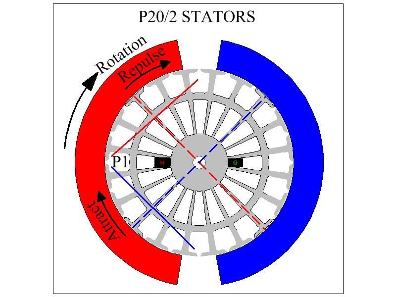
                    • Converting Repulsion mode motor to Attraction Mode

                      Originally posted by Ufopolitics #6001 View Post
                      Hey Sam,

                      Yes you are right, the P1 Comm Segment is kind off timing, considering rotation to be CW.

                      Now, all you've got to do is rotate the whole rotor CCW (in your mind of course, unless you have done this on a CAD Software) then you will realize that this set up (related to element chosen)is mainly based on repulsion from N/Rotor-N/Stator Bisectors. However, it will still rotate the way I had set or CW.

                      Now remember what I wrote before about this motors draining much less amperage if they run based on Attract Mode rather than repulse.


                      Kind Regards and Happy New Year for all!

                      Ufopolitics
                      I believe the following diagrams are all repulsion mode. They all seem to have the basic winding pattern you first established with the Radio Shack motor.

                      I added the brushes here to ascertain their exact location to the P1 coil and thus the exact commutator segment the coils would attach to...


                      Here is the P22 coil that shows the commutator and coil connections. It also is using your basic asymmetric winding pattern (as does the imperial).

                      I am using this diagram of the Radio Shack motor as it seems to be using the basic asymmetric winding pattern but it is showing a significantly different brush position. But in winding a N or S coil it is excellent in showing the direction of the wire winding from and to the commutator segments. Also I am assuming that the outer commutator is the FRONT commutator, inner is the aft commutator in general for these diagrams.


                      Here is the question. Taking the first P20 diagram, the N and S coils are reversed to convert to Attraction mode. Is this correct, Ufo?


                      Here is another question. If you have a motor built to the design of a repulsion mode, if you reverse the positive and negative connections of power input, does the motor change from repulsion to attraction mode? Of course if it is not neutral timining it will have to be reset the opposite offset from TDC.

                      Multo grazie, UFO!
                      Up, Up and Away

                      Comment


                      • Originally posted by Ufopolitics View Post
                        Hey Midaz,

                        I just found on same site you have shown before...the single cell type, and it looks great!

                        Gebattery|LiFePO4|LiFePO4 battery|Polymer lithium battery|lithium-Cells|LiFePO4 18650|26650|power battery|Electrically bicycle battery|Electrically motorcycle battery-Member Center

                        It is shown for EV Cars...but since it is single cell is modular, so you could add as many as you like to achieve the right bank...and my friend, 150 Ah...plus continuous 100 Amps discharge looks superb!

                        Only thing have to find out if it is a "6C" or lower charge-discharge capacity.

                        also look at the BMS and Sub BMS below on same page...looks like they could be programmed according to pack size and number of Sub BMS.

                        I would love you to be able to kick Imperial in the final straight flat line....with a "juicy" 72V 150-200 Amps...and wave them ALL Good Bye...would be something like a Nitro Fuel Injected by pressurized Turbocharged...

                        Regards


                        Ufopolitics
                        UFO

                        The 150amp lipos are great but too heavy for a light weight race bike. The 40 amps will give about 40amps continuous and about 80amps burst for 10 seconds, weight 3lbs each.

                        6c regular lipos have not been discussed, but close to 4c have. No one trusts any companies that claim over to have over 4c rating for reg lipos. The next generation of lithium batteries are lithium- sulfur.


                        For high density batteries these are the best value, weight 3lbs. Need 12 ~ 16 packs. ZIPPY Flightmax 8000mAh 6S1P 30C

                        For the big money racers, we have the best of the best! Turnigy nano-tech A-SPEC 4500mah 12S 65~130C Lipo Pack

                        Keep it Clean and Green
                        Midaz

                        Comment


                        • How to make a Graphene Super capacitor

                          Midaztouch,

                          Maybe you can incorporate this concept into something that would work better.

                          He speaks of it being both a battery and capacitor:

                          How to make a Graphene Super capacitor
                          How to make a Graphene Super capacitor - YouTube

                          Cheers,

                          IndianaBoys

                          Comment


                          • Question on Ajay's motor p6011

                            Hi Ajaya, here is a blow-up of your motor commutator.


                            I see it has 4 segments per pole, and the commutator segments are joined by a band. Did you put that on to join the segments as needed in an asymm motor? Could you explain what material you used and what was the connection mechanism? Did you design it or was that how the original motor was wired and the band was the manufacturer's design?

                            thanks, Sam
                            Last edited by sampojo; 01-03-2014, 05:35 AM.
                            Up, Up and Away

                            Comment


                            • Re: diagrams in p6011 for Ajaya

                              HI Ufo!,
                              wow really like the generator and attraction diagram. Studied them a bit and I can see my earlier post would need more interpolation to get those designs into a 20-pole Baldor. I have been kicking around a double rotor Baldor generator, joining 2 motors together. I can get my hands on another baldor too at my goldmine store, but the price is a little higher and I haven't jumped on it there. For the motor I am favoring attraction low amp mode. Maybe I could leave a little extra loop of wire and using connectors you could reconfigure a motor without even rewinding... I suppose I could use similar geometry. I see how the coil to segment geometry is shifted for each, so it appears my first guess on the attraction mode is wrong in post 6016.

                              So can the P15 diagrams be adapted to my 20-pole by maintaining the geometric relationship of the coils and their commutator segments?

                              TIA, Sam
                              Up, Up and Away

                              Comment


                              • 1 hp 15 pole

                                Hi Sam,
                                Originally posted by sampojo View Post
                                Hi Ajaya, here is a blow-up of your motor commutator.


                                I see it has 4 segments per pole, and the commutator segments are joined by a band. Did you put that on to join the segments as needed in an asymm motor?
                                Yes. It's a 15 pole motor with 60 commutator elements. As we need only 15 elements, I joined 4 elements to get only 15 elements on the commutator.

                                Originally posted by sampojo View Post
                                Could you explain what material you used and what was the connection mechanism?
                                It is normal solder wire that we use for soldering while making circuits - available in hardware store. A mix of tin and lead.

                                Sorry I didn't get your question on connection mechanism.

                                Originally posted by sampojo View Post
                                Did you design it or was that how the original motor was wired and the band was the manufacturer's design?
                                Yes. I designed and made it by myself. The manufacturer gave the design like that of any other motor. In my first attempt I soldered it very shabbily and the wires were coming out from the elements. It was neither serving the purpose nor looking good. Then I removed all the wires from the commutator elements and did it this way. I used a ring and poured the melted solder wire into it. After sometime, I removed the ring and filed to get 15 elements. It is very strong in holding the armature leads and looking good as well.

                                Regards and Namaste

                                Kumar

                                Comment

                                Working...
                                X