Announcement

Collapse
No announcement yet.

My Asymmetric Electrodynamic Machines

Collapse
X
 
  • Filter
  • Time
  • Show
Clear All
new posts

  • Ufopolitics
    replied
    Originally posted by YahwehisSpirit View Post
    Nope not the meter i had tested resistors and it zeroes out when probs touch eachother. The question was more do i have to scrape away the insulation and touch the probe to the bare wire to get a reading, asking because i dont want to damage my wire.

    lol I was using 29awg because it was closer to the gauge that was on the motor, funny thing is they had it wrapped with only about 30-35 turns. I actually have 2 rolls of 24 or 25awg but used the 29 worried i wouldnt have enough of the larger lol!!

    ok ill keep that in mind when i start playing with the timeing, What do you think of a bedini circuit recharging the batt that power the motor??

    If someone could please answer about shaving or not shaving away some insulation that woulf be amazing!!! Im itching so bad to get it wired!!!

    Hello YHS,

    I believe 29 awg is too thin for this motor...yours looks like a 550 body type, not the 256 body or the typical Radio Shack is, which is OEM wound with 30 awg.

    I really do not understand why you need to strip wire to measure it before winding coil in motor?!...unless you are going by the wire length table to resistance in ohms.

    All you need to do is to wind ONE COIL first...then strip the ends that are going to attach to the commutators elements and read it from the two end terminals.

    Just make sure you wind very tight, and pressing it on both sides of coil , MAKING SURE to leave room for the other two Coils seating right next to this first one...that is all.

    If you still wanna go with 29 awg, then do like 60 to 100 turns on each coil.

    Please write down your turn counting...as all coils must have exactly same total turns.

    This is it friend...just get it rolling


    Ufopolitics
    Last edited by Ufopolitics; 03-16-2015, 10:13 PM.

    Leave a comment:


  • YahwehisSpirit
    replied
    Thnkyou for helping further humanity

    Originally posted by Ufopolitics View Post
    Hello YHS,

    Ok, one good thing to do first is to make sure your meter is capable of reading low ohms with accuracy, plus read your meter's resistance.

    Measure your meter's resistance: Touch both probes, it 'should' read zero, if it don't...then it must be reset to zero...or deduct whatever measure is shown...since that would be your own meter resistance.

    Second: Get a low 1-10 ohms resistor and measure it to find out if your meter is accurate.

    Some good tutorials:

    Multimeter Tutorial/Resistance Tests

    Ohmmeter usage


    With 300 turns, even with 16 gauge (awg) you must get a reading, so there is something wrong with meter or contacts or something else.

    If you scratch just ONE wire, is no problem...but two or more strips within short turn distance could short coil...no good.


    After you are done winding, with identical (or very close) ohms readings on all coils, meaning you are good to go do some timing play...and yes, you could move to fire closer to either one stators center, while measuring draw and RPM's plus Torque...I do it all the time while I am running motors with a PSU (Power Supply Unit)...is the best way to adjust the timing in them.

    The Diagram I have shown is based on a NEUTRAL TIMING, meaning, firing coil right at center between both Stators, so there is a 50-50% share of Attract-Repulse. But remember that a three element commutator have a sweeping angle of 120º duration and space travel...so you must look at start and end points location related to stators(magnets).
    BUT, considering that NEVER, EVER the Coil center should align with ANY one of the STATOR's CENTER while coil is turned ON!

    A "One Ohm" instance is just a unit 'agreement' measure we have taken...but it could be anywhere between 0.6 to 2.0 Ohms per coil...You must realize that the higher the resistance, the more voltage would be required...even if very low amps are drawn.

    [IMG][/IMG]

    By looking at the pics of your small motor, I would say a 24 to 26 awg with around 30-50 turns per coil will be good enough...but, if you could go a few more turns, please do.


    Regards


    Ufopolitics
    Nope not the meter i had tested resistors and it zeroes out when probs touch eachother. The question was more do i have to scrape away the insulation and touch the probe to the bare wire to get a reading, asking because i dont want to damage my wire.

    lol I was using 29awg because it was closer to the gauge that was on the motor, funny thing is they had it wrapped with only about 30-35 turns. I actually have 2 rolls of 24 or 25awg but used the 29 worried i wouldnt have enough of the larger lol!!

    ok ill keep that in mind when i start playing with the timeing, What do you think of a bedini circuit recharging the batt that power the motor??

    If someone could please answer about shaving or not shaving away some insulation that woulf be amazing!!! Im itching so bad to get it wired!!!

    Leave a comment:


  • Ufopolitics
    replied
    Wiring-Timing

    Originally posted by YahwehisSpirit View Post
    My question for wiring is reading ohms, from what i have read and gather, each coil needs to be at 1ohm?
    Hello YHS,

    Ok, one good thing to do first is to make sure your meter is capable of reading low ohms with accuracy, plus read your meter's resistance.

    Measure your meter's resistance: Touch both probes, it 'should' read zero, if it don't...then it must be reset to zero...or deduct whatever measure is shown...since that would be your own meter resistance.

    Second: Get a low 1-10 ohms resistor and measure it to find out if your meter is accurate.

    Some good tutorials:

    Multimeter Tutorial/Resistance Tests

    Ohmmeter usage

    How do i read that? i get no reading with 300 turns, do i strip a little insulation? will that be detrimental if i scratch it much and continue wiring?
    With 300 turns, even with 16 gauge (awg) you must get a reading, so there is something wrong with meter or contacts or something else.

    If you scratch just ONE wire, is no problem...but two or more strips within short turn distance could short coil...no good.

    Ok UFO about the timing, what if you set the commutator a little off center with the armature to were green comm element is slightly closer too green coil yet still complete opposite side? The magnets in the housing are 1x2 I forced the housing manually with my hands as my wife wrapped the fiberfix around housing, some resin slipped throuh and seld magnets, perfectly because they were repelling. My brush housing caps, because of the way i had to take them off, spin freely in the housing to were i can set their position any way id like anytime. Itll be good for finding a sweet spot i can imagine...?
    After you are done winding, with identical (or very close) ohms readings on all coils, meaning you are good to go do some timing play...and yes, you could move to fire closer to either one stators center, while measuring draw and RPM's plus Torque...I do it all the time while I am running motors with a PSU (Power Supply Unit)...is the best way to adjust the timing in them.

    The Diagram I have shown is based on a NEUTRAL TIMING, meaning, firing coil right at center between both Stators, so there is a 50-50% share of Attract-Repulse. But remember that a three element commutator have a sweeping angle of 120º duration and space travel...so you must look at start and end points location related to stators(magnets).
    BUT, considering that NEVER, EVER the Coil center should align with ANY one of the STATOR's CENTER while coil is turned ON!

    A "One Ohm" instance is just a unit 'agreement' measure we have taken...but it could be anywhere between 0.6 to 2.0 Ohms per coil...You must realize that the higher the resistance, the more voltage would be required...even if very low amps are drawn.

    [IMG][/IMG]

    By looking at the pics of your small motor, I would say a 24 to 26 awg with around 30-50 turns per coil will be good enough...but, if you could go a few more turns, please do.


    Regards


    Ufopolitics
    Last edited by Ufopolitics; 03-16-2015, 02:21 PM.

    Leave a comment:


  • YahwehisSpirit
    replied
    Sweet spot.

    Originally posted by Ufopolitics View Post
    Hello YahwehisSpirit,

    Nice work, you have plenty of room for wiring there!

    Ok, below is the three pole CAD:

    [IMG][/IMG]

    Coils are color coded with commutator elements, so take a good look first at the way brushes seat related to stators (N-S Magnets).
    Then notice the green comm element is making contact to brush, therefore firing green NORTH coil (N-1), which seats right between N-S Upper side, generating a rotation indicated by top arrow.

    So, this is all about a 'sweeping angle' generated by comm element-brush and Fired Coil and Stators, like I have shown below:

    [IMG][/IMG]

    And of course you could adjust the timing by moving the brushes (or magnets, whichever is simpler) either to start firing closer to North Blue Stator CENTER...which would be a higher Repulse mode...OR, by doing the opposite...firing it closer to SOUTH RED Stator CENTER...where it would be more towards "attract mode".

    This Diagram is set at a 'Neutral Point' which fires right between both stators equally.

    Also, the wiring connections to commutator elements is "relative"...as I have done it right at center of coil...but it could be done on either side, just realizing the basics here.


    Thanks and please, post your results when you are done, so others learn from your work...


    Ufopolitics
    Ok first on wireing I started last night being excited after receiving your reply to post ufo. I shouldn't have as i and my wife were out with the baby all day and i was tired. being tiredi know I have 300 turn but i know i probably have more. Im going to re wrap to be exact. My question for wiring is reading ohms, from what i have read and gather, each coil needs to be at 1ohm? How do i read that? i get no reading with 300 turns, do i strip a little insulation? will that be detrimental if i scratch it much and continue wiring?

    Ok UFO about the timing, what if you set the commutator a little off center with the armature to were green comm element is slightly closer too green coil yet still complete opposite side? The magnets in the housing are 1x2 I forced the housing manually with my hands as my wife wrapped the fiberfix around housing, some resin slipped throuh and seld magnets, perfectly because they were repelling. My brush housing caps, because of the way i had to take them off, spin freely in the housing to were i can set their position any way id like anytime. Itll be good for finding a sweet spot i can imagine...?

    Leave a comment:


  • Ufopolitics
    replied
    Nice work

    Originally posted by YahwehisSpirit View Post
    So in the diagram for the 3 pole motor the coils are wound the same direction and one end of the coil is atached to the opostie side of commutator and other end is connected to oposite end of oposite side commutator.. correct? Also can someone fill me in i keep coming across a specific about how the brushes are to be set...?? Here are some pics of what i have so far. If someone can confirm my understanding of how to wrap and connect the coil that would help immeasurably as i could start wrapping the armature.
    Hello YahwehisSpirit,

    Nice work, you have plenty of room for wiring there!

    Ok, below is the three pole CAD:

    [IMG][/IMG]

    Coils are color coded with commutator elements, so take a good look first at the way brushes seat related to stators (N-S Magnets).
    Then notice the green comm element is making contact to brush, therefore firing green NORTH coil (N-1), which seats right between N-S Upper side, generating a rotation indicated by top arrow.

    So, this is all about a 'sweeping angle' generated by comm element-brush and Fired Coil and Stators, like I have shown below:

    [IMG][/IMG]

    And of course you could adjust the timing by moving the brushes (or magnets, whichever is simpler) either to start firing closer to North Blue Stator CENTER...which would be a higher Repulse mode...OR, by doing the opposite...firing it closer to SOUTH RED Stator CENTER...where it would be more towards "attract mode".

    This Diagram is set at a 'Neutral Point' which fires right between both stators equally.

    Also, the wiring connections to commutator elements is "relative"...as I have done it right at center of coil...but it could be done on either side, just realizing the basics here.


    Thanks and please, post your results when you are done, so others learn from your work...


    Ufopolitics

    Leave a comment:


  • HuntingRoss
    replied
    Originally posted by YahwehisSpirit View Post
    If someone can confirm my understanding of how to wrap and connect the coil that would help immeasurably as i could start wrapping the armature.
    I have started to do dummy runs on the first group to make sure the timing is correct and that the motor kicks off. I use some old wire and do a quick 5 or 10 turns and test. Chances are when you put it back together and connect it up, the comm on the brushes wont be the one you wired so just spin the rotor in your fingers and it should jump start the process. Test at 5v or so.

    Happy Hunting

    mark

    Leave a comment:


  • YahwehisSpirit
    replied
    Help

    So in the diagram for the 3 pole motor the coils are wound the same direction and one end of the coil is atached to the opostie side of commutator and other end is connected to oposite end of oposite side commutator.. correct? Also can someone fill me in i keep coming across a specific about how the brushes are to be set...?? Here are some pics of what i have so far. If someone can confirm my understanding of how to wrap and connect the coil that would help immeasurably as i could start wrapping the armature.
    Attached Files

    Leave a comment:


  • HuntingRoss
    replied
    Hybrid Sym / Asym Motor (Continued from #7384)

    Continued from Post #7384 http://www.energeticforum.com/271717-post7384.html

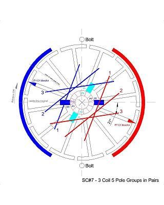
    SC#7 Build and Tests

    3 coil 5 pole groups in Pairs. 20 turns per coil @ 0.425mm wire. Schematic at the bottom and photos to follow.

    This is bordeline to not being able to complete. The last coil of one group overlaps the first coil of the other group causing a bump. This is compounded by the 5 pole coils cross the horizon of the shaft causing the wires to stack at the centre of the rotor. This makes the wires rise quickly at the centre making it difficult to avoid the commutator and the final coils are too level with the tabs to make an easy contact. I was just able to complete the wind at 20 turns per coil but had to devise a way to prevent the coils from falling out of the slots. I bound the wires in place by cotton thread by winding around the poles and thereby jumping from pole to pole at the top and bottom of the armature.

    5.38v PSU no load
    SC#7 - 5.06v @ 1.15A @ 1197rpm @ 3.75v out (5.82W)
    Connect SC#5 to SC#7 output
    SC#7 - 4.97v @ 1.98A @ 932rpm @ 1.82v out (9.84W)
    SC#5 - 1.82v @ 1.50A @ 684rpm (2.73W)
    Connect OEM 450W to SC#7 output
    SC#7 - 4.97v @ 2.04A @ 932rpm @ 1.75v out (10.14W)
    450W - 1.75v @ 1.48A @ 26rpm (2.59W)

    10.35v PSU no load
    SC#7 - 10.24v @ 1.10A @ 2676rpm @ 8.49v out (11.26W)
    Connect SC#5 to SC#7 output
    SC#7 - 10.08v @ 2.21A @ 2429rpm @ 6.35v out (22.28W)
    SC#5 - 6.35v @ 1.73A @ 3478rpm (10.99W)
    Connect OEM 450W to SC#7 output
    SC#7 - 10.09v @ 2.21A @ 2461rpm @ 6.37v out (22.30W)
    450W - 6.37v @ 1.63A @ 118rpm (10.38W)

    25.7v scooter controller no load
    SC#7 - 24.9v @ 1.59A @ 6772rpm @ 20.9v out (39.59W)
    Connect SC#5 to SC#7 output
    SC#7 - 24.1v @ 3.07A @ 6448rpm @ 24v out (fluctuating)
    SC#5 - 24v varies @ 2.53A @ 9165rm
    Connect OEM 450W to SC#7 output
    SC#7 - 24.1v @ 3.17A @ 6486rpm @ 17.9v out (76.40W)
    450W - 17.9v @ 2.21A @ 351rpm (39.56W)

    Scooter no load rear wheel 1149rpm

    Tether test 7.5kg 88% (approaching the OEM 8.5kg)

    [IMG][/IMG]

    --S--

    So, it's been bothering me how to compare different motor configurations. Some dismiss themselves but many have certain qualities which look like they may be useful. I've started to express outputs in Watts because the Volts/Amps readings vary wildly sometimes. But that still doesn't crystalise it for me.

    Now this may not be new, it may even be flawed, but the following does seem to bring a certain sense to the process.

    For me a motor must possess torque for the least expenditure of power to set itself above its competitors. As a baseline they must equal or better the OEM.

    (apologies if this doesn't tabulate very well - also I will call my static tether test 'torque' as it is a basis to compare the strength of motors by simply hitching it to a spring balance expressed in Kg.)

    24v motor tests :

    OEM~1.13A~3840rpm~27W~8.8kg
    SC5~3.60A~13128rpm~90W~5.7kg
    SC6~2.13A~8506rpm~53W~5.9kg
    SC7~1.59A~6772rpm~40W~7.5kg

    Expressing all of that as a percentage of the OEM :

    OEM~100%A~100%rpm~100%W~100%kg
    SC5~318%A~342%rpm~333%W~65%kg
    SC6~188%A~221%rpm~196%W~67%kg
    SC7~140%A~176%rpm~148%W~85%kg

    And for simple maths if a motor doubled the Watts and doubled the RPM then the nett result would be comparable to the OEM and would be expressed as %RPM divided by %Watts (%RPM/%W) which would equal One (1) in this example. If the result is more than 1 there is a nett advantage over the OEM.

    So for the above :

    SC5~342/333=1.03
    SC6~221/196=1.13
    SC7~176/148=1.19

    That puts SC7 ahead of the OEM as the RPM increased more than the Watts but this doesn't consider all three motors are under torque.

    With gearing the revs can be turned into torque. For example, halve the revs to double the torque. Assuming there is no change to the Watts, then :

    SC5 needs to be geared by 54%, SC6 by 49% and SC7 by 18%

    Applying those percentages to the motors will bring the revs down and bring the torque up to 100% :

    SC5~8525rpm
    SC6~5701rpm
    SC7~5758rpm

    OEM~100%A~100%rpm~100%W~100%kg
    SC5~318%A~222%rpm~333%W~100%kg
    SC6~188%A~148%rpm~196%W~100%kg
    SC7~140%A~150%rpm~148%W~100%kg

    %RPM/%W :

    SC5~0.67
    SC6~0.76
    SC7~1.01

    On a strictly theoretical analysis of the figures, SC7 can be geared to compensate for the shortfall in torque and the remaining RPM advantage is not gained by excessive power draw.

    Happy Hunting

    mark
    Last edited by HuntingRoss; 04-07-2015, 12:53 AM. Reason: Theory for comparative motor results

    Leave a comment:


  • YahwehisSpirit
    replied
    Most deffinately!!

    Originally posted by MagnaMoRo View Post
    Your armature pics look good.

    I used the flat side of a metal file to sand the pre-existing epoxy off of the sides of the armatures so that they fit snug together.

    I have no idea if gorilla glue will work, but I would recommend a fast curing two part epoxy. For this small job you can probably find small tubes of the stuff in your local hardware store.

    But, its all about experimentation in the open source community, that and sharing your results (good or bad).

    Keep going with it and let us know!
    Yeah lol i was using my box cutter to scrape at it... i think ill file it some more. Its not completely flush though because some of the laminations are bent ona corner pushing up in a small area..

    my fiber fix came in ^_^ and i got gorilla glue 2part 5min bond epoxy im going to use a small paint brush to paint the thin layer on the armatures and im going to put a coat between them to bond them as one...

    Im so excited about this but my damn commutators dont get here from china till the 26 of this month to the 20th of Freaking APRIL!!! and i cant seem to find anywhere else to get them... Ufo made a vid of m as king a commutator but where do you get the mica and stuff??

    Yeah im deff gunna keep posted so i gethelp and advice on the way!!!

    Leave a comment:


  • MagnaMoRo
    replied
    Originally posted by YahwehisSpirit View Post
    Thankyou!! So the many laminations epoxyed together make up the armature? Thankyou much!! ive been waiting to find out what kind to get!!!
    Your armature pics look good.

    I used the flat side of a metal file to sand the pre-existing epoxy off of the sides of the armatures so that they fit snug together.

    I have no idea if gorilla glue will work, but I would recommend a fast curing two part epoxy. For this small job you can probably find small tubes of the stuff in your local hardware store.

    But, its all about experimentation in the open source community, that and sharing your results (good or bad).

    Keep going with it and let us know!

    Leave a comment:


  • YahwehisSpirit
    replied
    ???

    Do i understand right? will gorilla glue work?

    Leave a comment:


  • YahwehisSpirit
    replied
    Thankyou for being Critical it helps ^_^

    Originally posted by MagnaMoRo View Post
    I think you mean "A few lamination came off you armature".
    The armature rotates. A stator is a motionless part.

    Not being critical, just helping.

    I would just press them together on the shaft and apply a thin cote of epoxy on the inside of the armature wire canals.

    use non-conductive epoxy. And be shure not to use something like a clear nail polish, as it may contain Acetone and could take off insulation on Coil wires.
    Thankyou!! So the many laminations epoxyed together make up the armature? Thankyou much!! ive been waiting to find out what kind to get!!!
    Attached Files

    Leave a comment:


  • MagnaMoRo
    replied
    Originally posted by YahwehisSpirit View Post
    Sorry i've been saying rotor and I've been reffering o the stator. A few Laminations came off on one stator. is that ok? do i need to re apply epoxy to reinsulate the stator???
    I think you mean "A few lamination came off you armature".
    The armature rotates. A stator is a motionless part.

    Not being critical, just helping.

    I would just press them together on the shaft and apply a thin cote of epoxy on the inside of the armature wire canals.

    use non-conductive epoxy. And be shure not to use something like a clear nail polish, as it may contain Acetone and could take off insulation on Coil wires.

    Leave a comment:


  • YahwehisSpirit
    replied
    Stator not Rotor lol

    Sorry i've been saying rotor and I've been reffering o the stator. A few Laminations came off on one stator. is that ok? do i need to re apply epoxy to reinsulate the stator???

    Leave a comment:


  • YahwehisSpirit
    replied
    Originally posted by HuntingRoss View Post
    It's unlikely to be bad as they're always in close proximity, but I would be surprised that there was sufficient room for that to happen.

    Happy Hunting

    mark
    Lol deff sufficient room and deff happening. Again is there a certain epoxy to get to re insulate my rotors as one. Ill post some picks later today reading UFO's post worrys me that i might not beable to use one.....

    Leave a comment:

Working...
X