Announcement

Collapse
No announcement yet.

My Asymmetric Electrodynamic Machines

Collapse
X
 
  • Filter
  • Time
  • Show
Clear All
new posts

  • Ufopolitics
    replied
    Nice work Mark...

    Originally posted by HuntingRoss View Post
    Hi to everyone. I've been quiet but not inactive. I submit for peer review, the SC#5.....

    Hello Mark,

    Ok, first, great work friend!...you have been -so far- taking the lead here lately with all your builds and testings.

    And this Post goes -as well- to All Members working in the development of Asymmetric Machines.

    First let's take a look at your Asymm-Symm Hybrid Config:

    [IMG][/IMG]

    And one basic side We ALL must realize is our "working" number of poles when we are sketching our CAD's, and before getting involved into winding...

    In your case above we have:

    [IMG][/IMG]

    And We are considering only those center poles, from bisectors on, towards rotation, which are the magnetically strongest poles...disregarding the end poles at coils start-end.

    Now, in your Hybrid design, you are also magnetizing the South end poles (in red), which is "similar" (quote marks because it is NOT exactly same thing) result as when we feed Input-Output in a typical Asymmetrical Design. However, you are doing it using only two brushes.

    The main point here that I want to direct towards is ...HOW COULD I ENHANCE THE PERFORMANCE?

    Ok, mainly, We must understand Symmetry...How it works?....before we move forward to build and make testings to compare results.

    Please, let's take a look first, at Your Symmetric Diagram (OEM) below:

    [IMG][/IMG]

    I have also marked the "working poles" here...and see the GREAT difference versus your design?

    First, Symmetry Designs "grab" as much space as it could within Geometry of rotor for each Coil that is wound in a WHOLE SERIES GROUP that comprehends the Total poles at Rotor...and, by the pictures of your original (OEM), I believe I am correct by choosing Five Poles per coil in the total group.

    Now, for your Hybrid Design based on only THREE working poles at each end, and Four when two brush elements are contacting...versus SIX at all times, with Symmetrical OEM...Your concept did pretty good friend!

    Now, a simple way to Increase your performance, would be to Expand the number of "Working Poles" per Group, starting by each coil...or something like:

    [IMG][/IMG]

    And... all We are doing here is winding Four Pole Coils...BUT, You could even try winding Five Poles per Coil in the Groups...And "our limit" here would be that as long as the ending contact last coil Bisector, would not be binding or too close to South Stator Bisector.

    Below Diagram is about expanding our Coils to Five Poles winding :

    [IMG][/IMG]

    Please, forgive me, as I did not move each coil number on above picture...but just the coil lines and "working poles"...

    But, take a look now at "working poles" number above, versus OEM in Symmetrical Design...they are about the same, except that when contacting only one comm element there would be five.

    In my opinion, this last design would be more 'suitable' to establish a testing comparison with OEM.

    The main point on this post, is to learn how to enhance performance by winding coils that comprehend the largest number of poles available, allowed by Geometry, within our coils design.

    If you All notice...all I have done is "replace/change" Throw Out Angles by "Number of Working Poles"......Maybe this way you all could understand this important issue in our designs much better.

    Hope this post help you out in your future designs...


    Regards


    Ufopolitics
    Last edited by Ufopolitics; 02-27-2015, 03:53 PM.

    Leave a comment:


  • HuntingRoss
    replied
    Photos added to http://www.energeticforum.com/271717-post7384.html


    Happy Hunting

    mark
    Last edited by HuntingRoss; 02-26-2015, 09:32 PM.

    Leave a comment:


  • MagnaMoRo
    replied
    Originally posted by HuntingRoss View Post
    I remember recently a comment about some kind of adhesive (?) which sounded like an American product so I'm completely unfamiliar with what it actually is/was.
    I used FiberFix to bond the two motor halves. I got it at Meijer, in the glue department. Very strong. Just cut to size, dip in water and wrap your part. Hardens like epoxi. Can be sanded. Look up my posted pics.

    MagnaMoRo
    Last edited by MagnaMoRo; 02-24-2015, 11:32 PM. Reason: Added link to post

    Leave a comment:


  • HuntingRoss
    replied
    Originally posted by YahwehisSpirit View Post
    Well that sure is interesting! I like the way you did that! im wprking with limited tools. Im curious if anyone without a welder bonded a half of two motor casings into one, hpw they did it.. I ordered 3 commutators from over seas expected thw middle of next month. though some germanium diodes that arnt supposed to even be here yet came a week and a half ago so i hope they'll be early!! My main goal for my motor is for it to run an radient energy pump.... So has anyone heard of radiant energy "backfilling" electronic equipment to where the equipment will run off the contiued "trikle" of radiant energy..?? My volt meter came in payed 24$ on amazon compared to 35$ on ebay. Quwstion about it its readings seem off the 1.5v aaa bats test at 1.6v and i tested a 18v nicad before charge (pretty dead) it tested -25v and in the middle of charger 19v fluctuating...havt tested it yet will after work but my question is, is that normal? Oh and can someone advize on a pretty accurate multimeter under 30$...???
    My first motor...I stuck the two bodies together with insulation tape because I was impatient to test it...worked a treat...I even did a field test with the electric scooter.

    Then I welded it.

    Soldering with a high wattage iron has been done for smaller motor bodies and I remember recently a comment about some kind of adhesive (?) which sounded like an American product so I'm completely unfamiliar with what it actually is/was.

    Happy Hunting

    mark

    Leave a comment:


  • YahwehisSpirit
    replied
    Much appreciated!!

    Originally posted by HuntingRoss View Post
    I cut the back end of the shaft from two rotors and bonded them together to make one rotor. The commutators didn't need to be removed which made the build very much simpler for a novice (me). And the shafts are just mild steel so no need for stainless. There are photos on my build if you search my posts.

    http://www.energeticforum.com/265600-post7095.html

    I suppose the most important thing is the shaft must be straight, if that's not stating the obvious.

    Happy Hunting

    mark
    Well that sure is interesting! I like the way you did that! im wprking with limited tools. Im curious if anyone without a welder bonded a half of two motor casings into one, hpw they did it.. I ordered 3 commutators from over seas expected thw middle of next month. though some germanium diodes that arnt supposed to even be here yet came a week and a half ago so i hope they'll be early!! My main goal for my motor is for it to run an radient energy pump.... So has anyone heard of radiant energy "backfilling" electronic equipment to where the equipment will run off the contiued "trikle" of radiant energy..?? My volt meter came in payed 24$ on amazon compared to 35$ on ebay. Quwstion about it its readings seem off the 1.5v aaa bats test at 1.6v and i tested a 18v nicad before charge (pretty dead) it tested -25v and in the middle of charger 19v fluctuating...havt tested it yet will after work but my question is, is that normal? Oh and can someone advize on a pretty accurate multimeter under 30$...???

    Leave a comment:


  • HuntingRoss
    replied
    Originally posted by YahwehisSpirit View Post
    Oh and again can i get any stainless steel sheft 3mm to use in the motor?
    I cut the back end of the shaft from two rotors and bonded them together to make one rotor. The commutators didn't need to be removed which made the build very much simpler for a novice (me). And the shafts are just mild steel so no need for stainless. There are photos on my build if you search my posts.

    http://www.energeticforum.com/265600-post7095.html

    I suppose the most important thing is the shaft must be straight, if that's not stating the obvious.

    Happy Hunting

    mark
    Last edited by HuntingRoss; 02-24-2015, 12:19 AM. Reason: link added

    Leave a comment:


  • HuntingRoss
    replied
    Hybrid Sym-Asym Motor

    Hi to everyone. I've been quiet but not inactive. I submit for peer review, the SC#5.

    Schematic at the end of this post and photos to follow shortly.

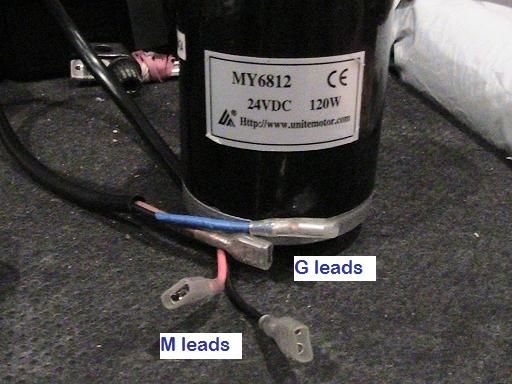
    The OEM motor -
    MY6812 24v 120w
    12 poll 2 stator 1 commutator 2 brushes
    0.53mm guage wire

    A symmetrical motor has one length of wire wound with coils in series, the wire returning to the origin.

    The route for current is one direction along two paths from brush to brush. If you picture the brushes at 3 and 9 o'clock, path 1 passes through 12 o'clock and path 2 passes through 6 o'clock.

    This embodiement retains the original structures of the OEM replacing only the wire and adding 2 brushes.

    --S--

    Title explained -

    The SC#5 (single commutator build 5) embodies the symmetric principle with one wire wound in coils in series returning to the origin. It departs from the principle as only 2no commutator sectors are so wired. The remaining comm sectors are wound as independent pairs giving a total of 6no pairs.

    In this way pairs are isolated after leaving their Motor brushes and are free to deliver their energy to the Generator

    brushes just prior to being re-energised 180o advanced.

    For this reason I have retained the description Asymmetric and hence HYBRID.

    --S--

    Winding.

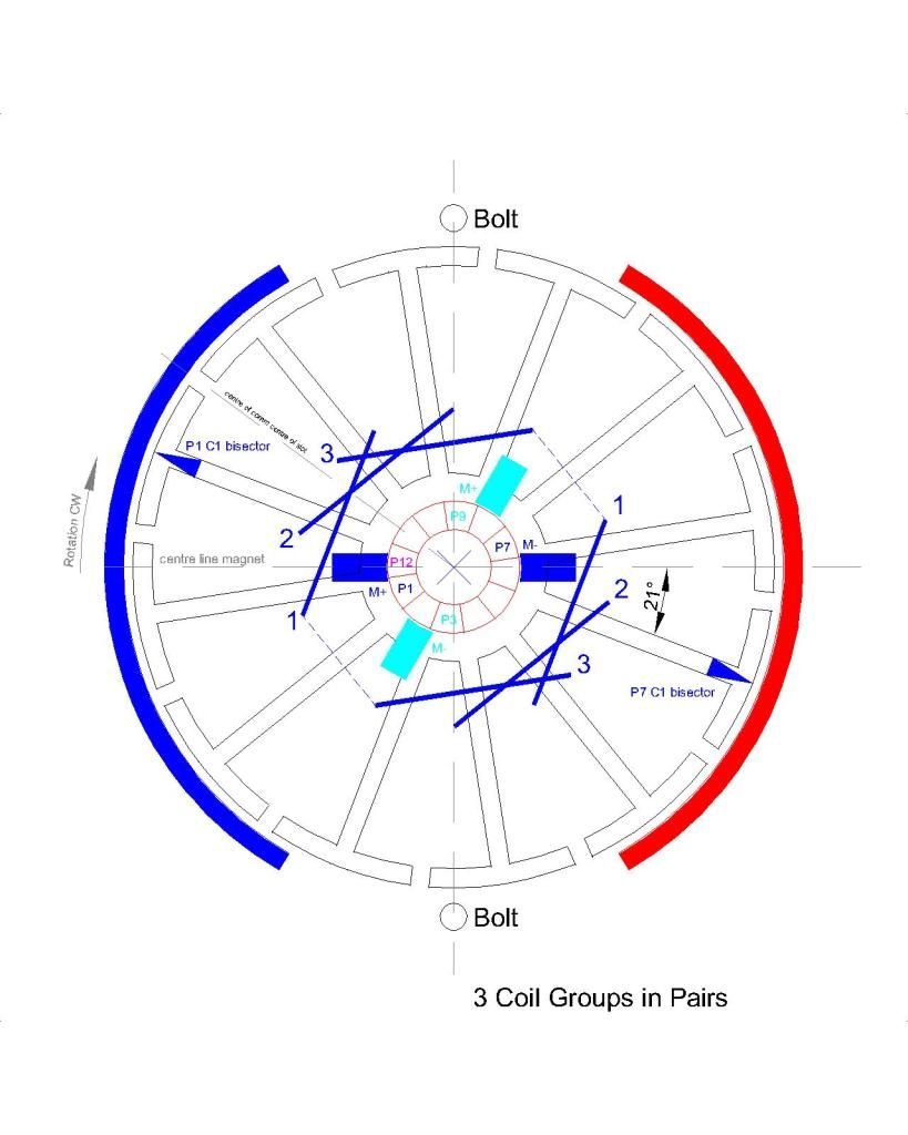
    3 coil groups in pairs. 11 turns 3 poles per coil of 0.5mm wire. Wound for CW rotation.

    Starting with P1 at 9 o'clock. Moving clockwise wind for north coil repulsion 3 coil groups. On completion of the first 3 coils hook over P7 comm and still moving clockwise wind another 3 coil groups (all coils are wound clockwise as seen from the front with shaft seen behind the coil). On completion of the second 3 coils hook over P1 comm and twist the two ends together tightening against the P1 tab. If this is not clear in the description, schematic below should help. This is one Pair of 3 coil groups.

    Pairs are as follow -
    P1 / P7
    P4 / P10 (P4 is perpendicular to P1)
    P2 / P8
    P5 / P11 (P5 is perpendicular to P2)
    P3 / P9
    P6 / P12 (P6 is perpendicular to P3)

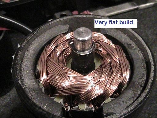
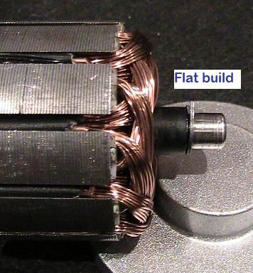
    This winding pattern gives a very 'flat' build, meaning the build up of wire towards the commutator is minimised and wire length is more balanced around the armature as the wind progresses.

    The coils on the 12 o'clock side energise North and the coils on the 6 o'clock side energise South. Both are in repulsion to their stators.

    The geometry of the 12 pole motor places the P1 Coil 1 bisector approximately 20o past the north stator bisector. The geometry of this motor doesn't allow for that figure to be greatly reduced. Reduction is crudely adjusted depending on poles grabbed per coil. Finer tuning would require re-engineering of the brush mounting plate.

    I tested each pair after winding at 5v PSU and measured amps -
    Pair 1 - 1.92A
    Pair 2 - 2.46A
    Pair 3 - 2.44A
    Pair 4 - 2.41A
    Pair 5 - 2.38A
    Pair 6 - 2.09A

    A feel (literally) for torque was assessed with each pair by pinching the shaft between my fingers and I was surprised from

    coil one onwards the reluctance for the motor to stall.

    Bench test SC#5 -
    5v @ 2.09A @ 2700rpm rising to 2800rpm
    10v @ 2.30A @ 6048rpm

    Bench test OEM -
    5v @ 1.18A @ 763rpm
    10v @ 1.18A @ 1546rpm

    --S--

    Static Scooter tests :

    The motors were plugged into the controller only. Not driving the rear wheel.

    SC#5 -
    25.1v @ 3.6A @ 13,128rpm (90.4W)

    OEM -
    25.1v @ 0.88A @ 3840rpm (22W)

    With the scooter tethered to a static object (washing machine) with a scale balance -
    SC#5 5.7kg
    OEM 8.525kg
    This is in effect a static stall torque test measured at the radius of the wheel.

    Findings -

    The static test places the SC#5 at 70% of the OEM torque.
    The 5v, 10v and 24v tests places the SC#5 at around 3-4x the revs and 2x the amps.

    The motor drives the back wheel through final gearing. The shaft sprocket is a 16 tooth the wheel sprocket is 88 tooth giving

    5.5:1. The OEM no load free spinning speed is 640rpm.

    --S--

    Adding Brushes -

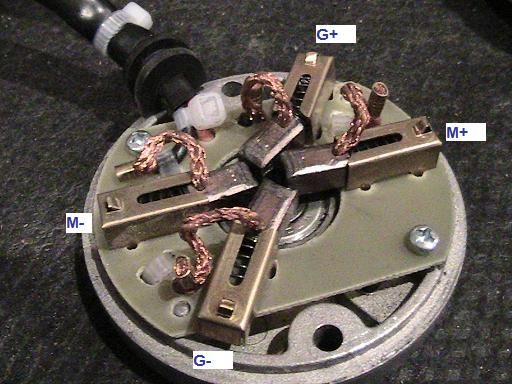
    The OEM brush holders are brass with 4no tab feet bent under the mounting board. My donor motor was stripped of its brushes and I drilled and mounted into the SC#5.

    As the repulsion coils rotate off their Motor brushes the collapsing north and south coils continue to repel but become increasingly attracted to their opposite magnet. Positioning the Generator brushes is set to allow the incoming attractive coils to assist rotation for as long as possible, accordingly they are set at P3 and P9.

    Bench test V out -

    5.4v PSU no load
    5.02v in @ 2.32A. 3.89v out @ 2706rpm

    10.28v PSU no load
    9.93v in @ 2.49A. 9.93v out @ 5919rpm

    The additional brushes added some load / resistance. These figures settle a little outwith the snapshot of testing.


    --S--

    Running a load off the SC#5 output -

    5.38v PSU
    SC#5 4.94v @ 2.28A @ 2692rpm (11.3w) @ 3.69v out
    Connect OEM load to SC#5 output
    SC#5 4.96v @ 2.47A @ 2644rpm (12.3w) @ 3.33v out
    OEM 3.33v @ 0.5A @ 475rpm (1.7w)

    10.33v PSU
    SC#5 9.96v @ 2.35A @ 5870rpm (23.4w) @ 7.82v out
    Connect OEM load to SC#5 output
    SC#5 9.89v @ 2.51A @ 5923rm (24.8w) @ 7.43v out
    OEM 7.43v @ 0.78A (5.8w) @ 1115rpm
    (note: the motor was warming and the 5870rpm had risen to above 6000rpm)

    Scooter 24v batteries and controller -
    OEM 120w : 25.1v @ 0.88A @ 3840rpm (22W)
    OEM 450w geared motor connected to controller : 24v @ 2.63A @ 471rpm (63W)
    (note: reference to OEM in all other cases is OEM 120w motor described at the top of this post)

    SC#5 24v @ 3.55A @ 13,025rpm (85.2w) @ 13.5v out
    Connect OEM 120w load to SC#5 output
    13.5v @ 0.93A @ 1990rpm (12.6W)
    Connect OEM 450w geared motor load to SC#5 output
    13.5v @ 2.33A @ 242rpm (31.5W)

    Despite the power hungry nature of SC#5 I'm interested to see that 31W was returned at the output. I will need to rig the twist grip on the scooter to free up my hands for testing the change in performance of the SC#5 when the load is added. From the 5v and 10v results the difference may be very small and this would be a significant use to balance the disparity between the OEM and SC#5 current draw.

    --S--

    THEORY.

    The shortfall in SC#5 torque at 24v can be adjusted by varying the final drive ratio to bring it up to the OEM benchmark and thereby trading revs for torque.

    The OEM @ 24v @ 3840rpm @ 5.5:1 delivers 640rpm at the wheel. (assuming some frictional losses)

    If the SC#5 @ 10v @ 6000rpm were to deliver 640rpm at the wheel the final drive ratio would be 6000/640 = 9.3:1

    With a 16 tooth drive gear the final sprocket would be 16x9.3 = 149 teeth @ 3mm pitch = 447mm belt = 142mm dia.

    The scooter wheel is a standard 5.5" 138mm dia so a gearing compromise would be required.

    Assume 5" 127mm dia = 400mm circumference @ 3mm pitch = 133 teeth : 16 = 8:1 final drive = 750rpm

    In theory then, modifying the 88 tooth sprocket to 133 tooth, the SC#5 might match the OEM torque and have a minor advantage in revs @ 10v (not 24v).

    However I think the gearing adjustment will only compensate at 24v in which case there is a large rev differential which is likely to be a troublesome feature within a small scooter platform.

    The more likely conclusion is the 13k revs @ 90watts (no load) will benefit from significant gearing down to raise the torque for a larger diameter wheel.

    Otherwise it is hard to justify 90W as a starting point compared to the OEM's 22W although getting 31w or more on the output is useful compensation.

    --S--

    Proposed Field Tests.

    Once I have modified the rear sprocket the 2no 12v batteries connected in series will be wired in parallel and the SC#5 will be tested against the OEM for speed and endurance @ 12v.

    Happy Hunting

    mark

    [IMG][/IMG]

    [edit: Try as one does to get things correct...The schematic should show the P7 coils in red]

    --S--
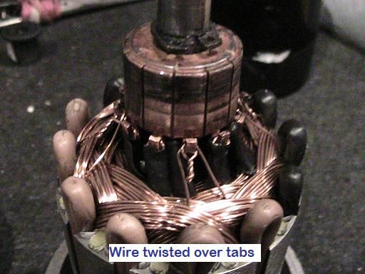
    26th Feb 2015 - Photo upload

    [IMG][/IMG]

    [IMG][/IMG]

    [IMG][/IMG]

    [IMG][/IMG]

    [IMG][/IMG]

    --S--

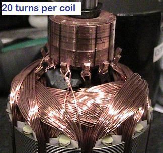
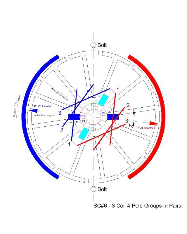
    28th Feb 2015 - SC#6 Build and Test Results

    So today I chopped one new OEM and wound it as follows -

    3 - 4 pole coil groups in Pairs - 20 turns per coil of 0.425mm wire. Schematic and photos to follow. Scooter torque test tomorrow.

    Something as simple as organising the pairs as described at the top of this post allows me to easily get an extra 4 turns per coil over my previous 16 which was a struggle.

    Results -

    5.39v PSU no load
    5.05v @ 1.33A @ 1713rpm. (6.72w). Vout 4.79v

    10.35v PSU no load
    10.23v @ 1.48A @ 3554rpm. (15.14w). Vout 10.44v [Note. I double checked that result - the Vout exceeds the Vin]

    --S--

    Curious with the increase in voltage I just completed a load test -

    10.36v PSU no load
    SC#6 ~ 10.14v @ 1.5A @ 3402rpm @ 10.51 Vout [15.2w]
    Connect SC#5 to SC#6 Vout
    SC#6 ~ 9.92v @ 2.80A @ 3071rpm @ 8.36 Vout [27.78w]
    SC#5 ~ 8.36v @ 1.84A @ 4803rpm [15.38w]
    Allowing SC#5 to warm up
    SC#5 ~ 8.36v @ 1.60A @ 4810rpm [13.38w]

    SC#6 running no load @ 15.2w rising by 12.58w under load which is less than the power being used by SC#5. Perhaps someone can explain that. I will check this again tomorrow when I conclude the scooter torque test.

    --S--
    29th Feb 2015 - Static Scooter Test, Output load tests and photo of build.

    26.5v @ the scooter controller output.
    SC#6 ~ 24.7v @ 2.13A @ 8506rpm @ 26.6v out [52.6W] No load
    Connect SC#5 to SC#6 output
    SC#6 ~ 23.5v @ 3.87A @ 8015rpm @ 26-40v out [90.95W] The output was fluctuating a lot, this doesn't happen with the OEM. A scope of this output would be interesting.
    SC#5 ~ 26-40v @ 2.52A @ 10,878rpm [notional watts 65W]
    Connect OEM 450W to SC#6 output
    SC#6 ~ 23.5v @ 4.09A @ 8054rpm @ 22.2v out [96.1W]
    OEM 450w ~ 222.2v @ 2.62A @ 442rpm [58.16W]

    Once again the SC#6 under load takes less power than the SC#6 no load + SC#5 load. Does anyone have a theory on this ?
    Notice also the OEM 450w pulling 58W compared to SC#5 load @ 31W.

    SC#6 static pull (torque) test 5.9kg (OEM 8.8kg)

    [IMG][/IMG]

    --S--

    [IMG][/IMG]

    --S--
    2nd March 2015 - SC#7 build commenced. 3 coil 5 pole groups in Pairs - 20 turns per coil. Test results for pairs as build progresses -

    Pair 1 - 5.21v @ 1.0A @ 934rpm
    Pair 2 - 5.14v @ 0.98A @ 1150rpm

    --S--

    Continued at Post http://www.energeticforum.com/272203-post7416.html as this post exceeds 12000 characters.

    Happy Hunting

    mark
    Last edited by HuntingRoss; 03-07-2015, 09:14 PM. Reason: Link to Post #7416

    Leave a comment:


  • YahwehisSpirit
    replied
    Re shaft

    Oh and again can i get any stainless steel sheft 3mm to use in the motor?

    Leave a comment:


  • YahwehisSpirit
    replied
    How bad is it?

    Originally posted by HuntingRoss View Post
    Selected quotes from UFO's post #7374 above.


    I avoided all the commutator and shaft issues by taking two motors and bonding them back to back. The one issue to resolve in that build is alignment of shafts, but it was pretty straight forward with care.

    Happy Hunting

    mark
    What do you mean by bonding two motors?

    ok so i managed to pull the tabs pretty decently but i damaged it a little bit when i was getting it off the shaft. I thought i cut off all the bonding on the shaft but not all Im posting some pictures can someone tell me if the comutator is damaged beyond use!!!!!
    Attached Files

    Leave a comment:


  • HuntingRoss
    replied
    Originally posted by YahwehisSpirit View Post
    My wire just came in the mail just now! Two rolls of 24awg and 1 roll of 29awg though now i feel i should have gotten two 29awg or even 3! Yeah while at work i read up on it and even found a tool on ebay for 12$ with diff rods for diff size motor to remove pinions called a "pinion puller".

    Question: Can i buy just any stainless steel 3mm rod to then cut for a longer shaft? And may someone point me to a good plac to find out how to safely remove comutators to use on other motors!!!
    Selected quotes from UFO's post #7374 above.

    To pull one commutator out to use it on main motor you have to do it EVENLY FROM BELOW, meaning, DO NOT PUSH ONLY from one element or it will brake apart. Do not try to turn commutator while on shaft either, shaft has straight splines and you will brake it if forcing to turn it.

    When pressing the second commutator, make sure it is perfectly aligned to bottom one (the original that came with motor), meaning, aligning element to element in a linear fashion, as well as when you solder the casing ring, make sure it will hold brushes seating identical above and below.

    you need to spread open each commutator hook, going from above to brake them apart to be able to pull wires out with a fine needle nose pliers, do it to both motors commutators. Do not apply heat with a soldering gun, as you may brake the comm copper elements from mica, then commutator is not good anymore.
    I avoided all the commutator and shaft issues by taking two motors and bonding them back to back. The one issue to resolve in that build is alignment of shafts, but it was pretty straight forward with care.

    Happy Hunting

    mark

    Leave a comment:


  • YahwehisSpirit
    replied
    Thankyou!

    Originally posted by HuntingRoss View Post
    I have never had to fix a broken comm sector but I suppose with reasonable care it could be bonded with an appropriate adhesive. Getting it lined and level sounds like a problem, if it's proud of the true face then the brushes will suffer. Go for small sideways twists and you'll feel the tab release.

    I recently read an 'Instructable' on cordless drills being chopped for robot builds. It covered the left hand threads and small lock screws, so I think that would give you all the info required to strip one down. It didn't seem that excessive force was required.

    Happy hunting

    mark

    Oh...and I forgot to mention the coils...more turns of thinner wire seems to be the best way to boost the resistance.
    My wire just came in the mail just now! Two rolls of 24awg and 1 roll of 29awg though now i feel i should have gotten two 29awg or even 3! Yeah while at work i read up on it and even found a tool on ebay for 12$ with diff rods for diff size motor to remove pinions called a "pinion puller".

    Question: Can i buy just any stainless steel 3mm rod to then cut for a longer shaft? And may someone point me to a good plac to find out how to safely remove comutators to use on other motors!!!

    Leave a comment:


  • HuntingRoss
    replied
    Originally posted by YahwehisSpirit View Post
    Its Yahweh is Spirit.

    Yeah on one motor i tried to pry the tabs with a small flat head but eaded up prying one of the copper contacts off the comutator...is that fixable? its a pretty decent 9v motor for a dremmel..
    My main motor is an 18v motor from a cordless drill I have 2, 1 for extra parts i.e second comutator etc.. Question, does anyone have experience with taking the gear off the motor that runs the gear box??? I pulled and pulled and pulled to no avail

    As to the gauge of wire does the more wraps increase ohm or is it gauge wrapped? would smaller gauge for more wraps to equal 1 ohm be better than a larger gauge with less ??

    My electrical technical fire has started again, it hasn't burned like this since i was told what wasn't possible for electricity. A really crazy one is I was really really into radiant energy and got deep into it in 2010 but in 2011 i went and lived in the woods for a year and came back june 2012. When i was into it there wasnt much video to watch on youtube about overunity well not much with alot of meat and what was there you had to dig and dig and do aloooooooooot of reading. Ufopolotics I am greatly appreciative for Yahweh opening your eyes to these simple truths that unify us in his pattern
    I have never had to fix a broken comm sector but I suppose with reasonable care it could be bonded with an appropriate adhesive. Getting it lined and level sounds like a problem, if it's proud of the true face then the brushes will suffer. Go for small sideways twists and you'll feel the tab release.

    I recently read an 'Instructable' on cordless drills being chopped for robot builds. It covered the left hand threads and small lock screws, so I think that would give you all the info required to strip one down. It didn't seem that excessive force was required.

    Happy hunting

    mark

    Oh...and I forgot to mention the coils...more turns of thinner wire seems to be the best way to boost the resistance.
    Last edited by HuntingRoss; 02-21-2015, 09:24 PM.

    Leave a comment:


  • YahwehisSpirit
    replied
    Thankyou Very Much!!

    Originally posted by HuntingRoss View Post
    Yahwe

    I found the most effective method to lift the tabs was to use some flat nose pliers. Press them flat to the commutator before lightly gripping the tab and then small twists to break the seal. Then a fine blade to ease them open.

    On the wire gauge question. I understand the gauge is chosen such that the coil pairs or coil groups for your wind are in the region of One ohm.

    Happy Hunting

    mark
    Its Yahweh is Spirit.

    Yeah on one motor i tried to pry the tabs with a small flat head but eaded up prying one of the copper contacts off the comutator...is that fixable? its a pretty decent 9v motor for a dremmel..
    My main motor is an 18v motor from a cordless drill I have 2, 1 for extra parts i.e second comutator etc.. Question, does anyone have experience with taking the gear off the motor that runs the gear box??? I pulled and pulled and pulled to no avail

    As to the gauge of wire does the more wraps increase ohm or is it gauge wrapped? would smaller gauge for more wraps to equal 1 ohm be better than a larger gauge with less ??

    My electrical technical fire has started again, it hasn't burned like this since i was told what wasn't possible for electricity. A really crazy one is I was really really into radiant energy and got deep into it in 2010 but in 2011 i went and lived in the woods for a year and came back june 2012. When i was into it there wasnt much video to watch on youtube about overunity well not much with alot of meat and what was there you had to dig and dig and do aloooooooooot of reading. Ufopolotics I am greatly appreciative for Yahweh opening your eyes to these simple truths that unify us in his pattern

    Leave a comment:


  • HuntingRoss
    replied
    Originally posted by YahwehisSpirit View Post
    Is it possible for someone to link me to the part of thread that talks about removing the wires from the comutator And gauge wire best used in rewireing. I ordered 29 and 24 gauge. Im in the process of engineering a portable "self continued energy manifestor" asymmetrical motors are a key in my design.
    Yahwe

    I found the most effective method to lift the tabs was to use some flat nose pliers. Press them flat to the commutator before lightly gripping the tab and then small twists to break the seal. Then a fine blade to ease them open.

    On the wire gauge question. I understand the gauge is chosen such that the coil pairs or coil groups for your wind are in the region of One ohm.

    Happy Hunting

    mark

    Leave a comment:


  • YahwehisSpirit
    replied
    Advice

    Is it possible for someone to link me to the part of thread that talks about removing the wires from the comutator And gauge wire best used in rewireing. I ordered 29 and 24 gauge. Im in the process of engineering a portable "self continued energy manifestor" asymmetrical motors are a key in my design.

    Leave a comment:

Working...
X