Announcement

Collapse
No announcement yet.

My Asymmetric Electrodynamic Machines

Collapse
X
 
  • Filter
  • Time
  • Show
Clear All
new posts

  • UFO

    The only Chance we have to get maximum performance and extra brushes, is with the singular coils = A1MoGen.

    It's seem to me that pair winds and group winds there is NO possibility of adding extra brushes to collect the collapsing field without hindering asymetric motors.

    Not to waste anyone's time... shouldn't checking the extra brush and Singular Coils be the main/top priority!? Wouldn't you agree?

    Midaz
    Last edited by Midaztouch; 05-10-2015, 05:42 PM.

    Comment


    • Question about the reversed locations of C1-C6

      Originally posted by Ufopolitics View Post
      Hey Sam,

      First You have there a "Unique" design...a Four (4) Stator and a Ten (10) Pole Rotor...no such a design in our 'marketplace'...
      Normally a Four Stator Symmetric Machine would start at Sixteen (16) to Twenty (20) Poles and up...So, You have a very 'Narrow Margin" to play with expanded Groups or Pairs...reason why I recommended to go Single Coils.


      So it is not the fact of "undesirable" Pairs nor Groups now...but you are trying to reach for the lowest amperage draw or the sweet spot, and I see you have not enough Angle to play towards Attraction without leaving much space at repulse.


      Yes, exactly the fact that Garry had reached a very ultra low amp draw at very high RPM's...means We could reproduce this "phenomena" at any level within any Asymmetrical Structure Design.

      The "Potential Explanation" I have given before here...it is 'no secret'...it is about adjusting the Firing to occur more towards the South Stator (Attract Mode) than the North (Repulse)

      Now, if you have a very CLOSE Angle between Both Pairs, Groups or even Single Coils Bisectors being fired by two commutator elements contacting both Motor Brushes to the 90º Bisector Angle from two N-S Stators (your case of four stators)...Then, no matter how much you try to fire further away from North...you are very limited before passing with "Leaving" Circuit Bisector the South Stator Center line (Bisector).


      Look at your Settings above...out of the Fixed 90º from Stators Bisectors you have more or less around 85º from Bisector of Repulse Group to Bisector of LEAVING Group at Attract. That is too narrow margin to look for sweet spots.

      Now, getting back at Garry's set up with the Five (5) Pole Radio Shack AN1...He had approximately 144º between both Pairs Bisectors ON, within 180º from the Two Stators Bisectors...which means He had somewhere around 36º to play searching for the sweet spot...or 18º from North and 18º to South Attract in 'Neutral Position'... And as He mentioned before...the best timing occurred more towards attract mode...which could have been 21º away from North...and 15º to attract at South Stator...or somewhere around that combination.

      ¿Comprende?


      You gotta have room to move brushes searching for the sweet spot...or else you are fixed again, even if you narrow the two bisectors with single coils...

      You answered yourself on that question...by putting the SAME 10 pole Rotor from a Two Stator to a Four Stator...you are narrowing the Interaction Angles fro 180º to 90º...


      [IMG][/IMG]

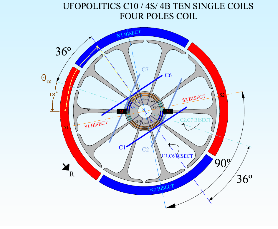
      Note on the Four Pole Coils Diagram above...the Angle between both 'Circuits' being fired, are reduced now from 85º previously to 36º...meaning, you could get further away from North (less repulse) and still not passing the South Stator Bisector...

      Now, the "Perfect Neutral" position for this case would be setting the 36º exactly in the center of 90º angle from stators...right?...and that would be 90-36=54/2=27º...meaning you would start firing exactly 27º away from North of C1 and 27º closer to South Stator Bisector of C2.

      So, firing closer C2 Bisector to the Attract South Stator Bisector, say at 20º...would set your repulse at 34º right?

      Concluding here...I believe your sweet spot should be from that Neutral spot towards closing the gap to the Attract Stator...As I am sure that in higher percentage of attract mode, your motor amps would start dropping real low.

      Is up to you to MARK your LIMIT ANGLE for Attract Mode...once Bisectors starts getting too close...and motor starts slowing down.


      Any "untunable" machine would NOT be a good learning tool my friend...leave those for when we are ready to set a fixed sweet spot...cause we already know how to set it even with our eyes closed...

      Every time you change by expanding or narrowing coils, pairs or groups ...everything must change as far as alignment and timing...

      If I were you, I will try before to work with an adjustable model...a simple one, before moving to Baldor...This Ten Poles and Four Stator could be a great learning tool to find the Gap where that sweet spot is...


      My pleasure friend


      Ufopolitics

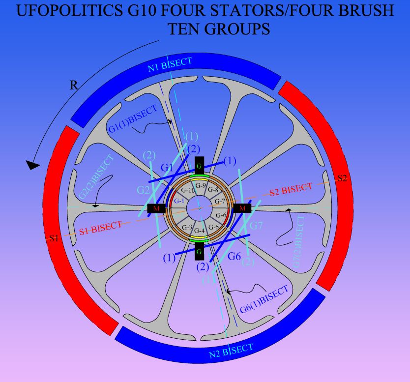
      Relatively speaking I think the transition diagram for my quad stator 10-pole has the same orientation. I have slightly altered the 2 diagrams to show how I understand the timing settings. On both diagrams I am looking at the same angle theta actually equal to 48 degrees, drawn around the left Motor brush.

      This first one is with the G1 winding and G1 commutator element:


      Now this is with the single coil winding, and again looking at the timing for the left motor brush but using the coil on the same side as G1, but is now labelled C6. The brush however is of course really activating commutator element G1, which should most likely belong to C1 coil element.


      Your diagram shows the wiring for each coil now going to the opposite side of the rotor. While it seems the "symmetry" here may allow these to be interchanged, I would find keeping the near coil to the left motor brush as C1 instead of C6 much easier to wind since the coil is closer to the brush side of the motor then.

      Does it have to be as shown or is this just a slight oversight, where it would be better for winding if C1 and C6 should actually be reversed?


      Thanks!
      Last edited by sampojo; 05-11-2015, 05:03 AM.
      Up, Up and Away

      Comment


      • Originally posted by sampojo View Post


        Hey Sam

        The width of your brushes is very important for the critical angles! Are your brushes the same size as a commutator segment?


        Follow me... If I were you, I would wind your motor with 3poles Singular Coils = A1MoGen!
        Remember, I set the guildline for the A1MoGen ="Singular Coils are the same size as the magnet."

        Keep it Clean and Green
        Midaz
        Last edited by Midaztouch; 05-11-2015, 11:28 AM.

        Comment


        • Brush width

          Hi Sam

          Can you comment on the exact width of your brushes relative to the size of your comm segments please. A comm segment being 36º wide.

          Happy Hunting

          mark

          Comment


          • Originally posted by Midaztouch View Post
            UFO

            The only Chance we have to get maximum performance and extra brushes, is with the singular coils = A1MoGen.
            Why don't you go to your Thread and keep doing 'your advertisement' about the a1 mogen there?

            Who said "We" need "extra-brushes"?...You did?

            It's seem to me that pair winds and group winds there is NO possibility of adding extra brushes to collect the collapsing field without hindering asymetric motors.
            "It seems to You" pair and group windings...bla,bla,bla...are just "Your" assumptions, you have not build any of those types, therefore can not tell absolutely nada about them.

            Not to waste anyone's time... shouldn't checking the extra brush and Singular Coils be the main/top priority!?

            Midaz
            But You DO ARE wasting everyone's time here.

            Garry Childers clearly demonstrated the A2 (Your Single Coil 'Design') even taken to a small motor is far Inferior to the A1 Pairs, by over 3000 RPM's above, same amp draw because it was the EXACT same amount of wire, therefore, same resistance, therefore same amps. However the TOTAL result as Speed is far superior.

            Mark (Hunting Ross) demonstrated the 12 Pole model He built based on 'your design' is better used for a Heater appliance, as it is a huge Amps hungry motor.


            The single coils take much less space, right, as a more compact field, right also, however, it does that around a smaller amount of core mass of rotor than any pair or group wind does, therefore, Single Coils does not have the same Heat Sinking Capacity and much less throw out angle (less speed).


            Wouldn't you agree?
            NO, I DO NOT AGREE!...I have stated that a long time ago, I just do not understand why do you keep addressing me ever again after all the BS you have pulled out here?

            Did you 'forget'?...CAUSE I DID NOT!

            You keep disturbing this thread!

            You keep disturbing excellent people here that are doing SUPERB Testings like Garry Childers.

            If I answered to your posts was in order for OTHERS not to get confused with all your BS questions.

            I appreciate if you do not address to me anymore.

            I would be ignoring all your post here from now on.

            AS I ALSO RECOMMEND ALL OTHER MEMBERS ATTENDING THIS THREAD TO DO


            YOU HAVE YOUR OWN THREAD, SO, GO THERE AND EXPOSE THERE ALL YOUR "ADVANTAGES" AND "SERIOUS" TESTINGS.


            Ufopolitics
            Last edited by Ufopolitics; 05-11-2015, 11:38 AM.
            Principles for the Development of a Complete Mind: Study the science of art. Study the art of science. Develop your senses- especially learn how to see. Realize that everything connects to everything else.― Leonardo da Vinci

            Comment


            • Come on Raul/UFO

              What!? Are you going to do like you did before!?

              Use racial slurs
              profanity
              Belittling
              doctored emails
              Post my home address
              home telephone number
              Private email addresses
              All cellphone info
              Other Members personal info
              Fake medical records
              Then lie to the admin and ask them to ban me

              What next from you!?

              I'm helping people do the singular coil = A1MoGen motors correctly! I don't want to fight with you. I'm just helping. You had a mistake. If you want all the credit, you can have it but DONT mess up my A1MoGen design.

              Be cool

              Midaz
              Last edited by Midaztouch; 05-11-2015, 01:58 PM.

              Comment


              • Originally posted by sampojo View Post
                Relatively speaking I think the transition diagram for my quad stator 10-pole has the same orientation. I have slightly altered the 2 diagrams to show how I understand the timing settings. On both diagrams I am looking at the same angle theta actually equal to 48 degrees, drawn around the left Motor brush.

                This first one is with the G1 winding and G1 commutator element:


                Now this is with the single coil winding, and again looking at the timing for the left motor brush but using the coil on the same side as G1, but is now labelled C6. The brush however is of course really activating commutator element G1, which should most likely belong to C1 coil element.


                Your diagram shows the wiring for each coil now going to the opposite side of the rotor. While it seems the "symmetry" here may allow these to be interchanged, I would find keeping the near coil to the left motor brush as C1 instead of C6 much easier to wind since the coil is closer to the brush side of the motor then.

                Does it have to be as shown or is this just a slight oversight, where it would be better for winding if C1 and C6 should actually be reversed?


                Thanks!

                Sam,

                The ONLY reason why I did this design based on Single Coils was because of your set up, which -as I explained before- is Unique.

                There are No Ten Pole Rotor spinning within a Four Stator Housing. Normally it should have been a Twenty Pole, then a Pair Wind or Group Wind would be the perfect set up.

                Now, as you notice there is absolutely no time, not enough sweeping angle for Generation stage to develop properly.


                Besides that, I highly recommend to use as much wire as you could there, and as finer as you could get as preferably Multi-Filar strands.

                Otherwise it would be another "Heater Element" as Mark (Hunting Ross) built based on the a1 mogEn.

                About the reversing C1 to C6 you are right, I just did not change the original commutator elements labeling from the old group diagram. But you know , and realized...all this hooking wires to elements is completely relative as I also mentioned before. Just have to look for the best convenient end related to brush positioning.


                Regards friend


                Ufopolitics
                Principles for the Development of a Complete Mind: Study the science of art. Study the art of science. Develop your senses- especially learn how to see. Realize that everything connects to everything else.― Leonardo da Vinci

                Comment


                • Originally Posted by Midaztouch View Post
                  Singular coils work for EVERY... Not some... but every!
                  Originally posted by HuntingRoss View Post
                  Not so !

                  I built your single coil motor months ago and it remains the most power hungry space heater I have ever built in my short motor career...@ 7.0A @ 5v @ 1795 rpm 'no load'.

                  So I'm not surprised at your recent 'test' results indicating huge 'no load' power consumption.


                  Happy Hunting

                  mark
                  Just an opinion on the a1 mogEn...from Hunting Ross
                  Principles for the Development of a Complete Mind: Study the science of art. Study the art of science. Develop your senses- especially learn how to see. Realize that everything connects to everything else.― Leonardo da Vinci

                  Comment


                  • Originally posted by Ufopolitics View Post
                    Just an opinion on the a1 mogEn...from Hunting Ross
                    Raul


                    Your trying to say the wire gauge was too thick. Every motor builder here knows it.
                    That why I asked Mark, " How would YOU fix the motor?" It was a simple fixable mistake.

                    Anything else?

                    Midaz
                    Last edited by Midaztouch; 05-11-2015, 12:14 PM.

                    Comment


                    • Originally posted by Ufopolitics View Post
                      Here is a drawing with both versions of the All North Five Poles, the AN-1 (Pairs) and the AN-2 (Single Coils).

                      [IMG][/IMG]

                      AN-1 & AN-2 CHARTS TOGETHER:

                      [IMG][/IMG]

                      The Higher RPM's from the AN-1 is understood as each motor actuating circuit (Pairs) comprehends Three (3) Poles, versus Single Coils which takes Two (2) Poles...here comes the Throw Out Angle difference that I have explained before.

                      Garry utilized the same amount of turns and same awg contained in the Pair, and duplicated into the Single Coil, as He did for all other replications, that is why there is no much amp draw difference between them when the sweet spot is found (green high light).

                      Here it would be very interesting to see the Torque difference or equal mechanical loads applied to both machines.

                      Ufopolitics

                      @Garry Childers:


                      Garry, could you do me a favor?

                      Could you just run for at least a steady half hour both -at no load- AN1 & AN2 while measuring heating on each of them?

                      Please have some damped cold towels handy when testing the A2 (Single Coils)

                      And please, let Us know the results.


                      Regards


                      Ufopolitics
                      Principles for the Development of a Complete Mind: Study the science of art. Study the art of science. Develop your senses- especially learn how to see. Realize that everything connects to everything else.― Leonardo da Vinci

                      Comment


                      • Originally posted by Midaztouch

                        Anything else?

                        Midaz

                        Yes, disappear from here, get lost, go to your thread
                        Principles for the Development of a Complete Mind: Study the science of art. Study the art of science. Develop your senses- especially learn how to see. Realize that everything connects to everything else.― Leonardo da Vinci

                        Comment


                        • This is open Forum. Anyone can post and build

                          [IMG][/IMG]

                          Nice CAD Raul/Ufo but...

                          Originally posted by Midaztouch View Post

                          Can you ADD extra brushes to either designs to collect the collapsing field? I don't want to reduce the performance of the machine/magnetic drag.

                          In your opinion, is it possible to do what I'm saying? Because anything besides that would be a waste of time. Don't you agree!?

                          Midaz
                          Originally posted by Ufopolitics View Post
                          As soon as P2 and P16 gets fully disconnected from Input, this coils would be in a kind of "limbo", where their previously oriented domains with North direction would get somehow in a 'loose status' just for nano seconds, then easily influenced by both South Stators Magnetic Fields...this would cause a Counter Orientation of the ferromagnetic comprehended core, which would be completely "compatible" with the natural collapsing field and Voltage polarity reversal.

                          We must realize that every time a ferromagnetic core approaches a magnetic field Pole, the field will "expand" and that specific Pole will take over that portion of the core under the inflluence.

                          IMO, at this early, primitive stage is too soon and too close to start collecting energy (by setting extra brushes), since it may create "Influence Conflicts" with the Coils being energized by direct input, since they are too close.

                          I recommend to set the Generator Brushes further away as possible from this 'conversion' stage, and as closer as possible before entering the next Input Cycle, this way we will 'suck out' all the reversed plus the induced energies, leaving a "Blank" clean Coil to receive next input, resulting in much less sparking.

                          However, all this are just assumptions based on magnetism and electrical behavior 'theories' as well as "not theories but reality", however, complex interactions requires that all of this must be tested/checked at different angles in order to determine which setting will deliver better performance and output.

                          Just my opinion.


                          Ufopolitics
                          It seems like the A1MoGen meets the requirements.

                          Originally posted by Midaztouch View Post
                          With the Singular Coils = A1MoGen, I believe that you can add extra brushes to collect the collapsing field... There is plenty of room to add the extra brush with no interface.

                          Look at the CAD. They fit and with with room to find that "Sweet Spot". Don't you think so!?

                          UFO

                          The only Chance we have to get maximum performance and extra brushes, is with the singular coils = A1MoGen.

                          It's seem to me that pair winds and group winds there is NO possibility of adding extra brushes to collect the collapsing field without hindering asymetric motors.

                          Not to waste anyone's time... shouldn't checking the extra brush and Singular Coils be the main/top priority!? Wouldn't you agree?


                          Midaz

                          Mark's half a motor, 1 commutator design, proves that you can add extra brushes. But when you add extra brushes to the Singular Coils = A1MoGen there is room to adjust them for Sweet Spot and maybe acceleration underload.

                          Mark, with your pair & group winds, I'm sure it created magnetic drag when you collect energy from the collapsing field to power a load with your design. Is that correct?... If you want to try for acceleration unload. Frist you shoud try 4poles Singular Coils = A1MoGen adjusting your gen brushes towards the repultion bisector. Then try the 5poles Singular Coils = A1MoGen


                          Keep it Clean and Green
                          Midaz

                          Don't forget to use thinner wire... More turns = more Torque
                          Last edited by Midaztouch; 05-11-2015, 12:53 PM.

                          Comment


                          • a1mOgEn

                            a1mOgEn quick "review":

                            Originally posted by Midaztouch View Post
                            The A1MoGen worked fine on a DC Power Supply. After I review the vid, I will put it up soon.
                            The "great Testing Video"...

                            [VIDEO]https://m.youtube.com/watch?v=xwcPckoSbtA[/VIDEO][/QUOTE]

                            The "poor" motor consumed over 20 AMPS AT NO LOAD NO MATTER what Voltage was applied...


                            Text copied from "The Designer's You Tube Channel":

                            Published on Apr 27, 2015

                            1.9volts @ 21amps... 40 watts starts RPMs. Start of vid
                            20Volts @ 21apms... 420 watts vid's peak RPMs at the end of vid
                            Originally posted by Midaztouch View Post
                            I invited DADHAV to our group because I got tired of the runaround. I needed a big boy to set thing straight. And he did his thing!
                            Dad's Hav opinion on video tests...

                            The DadHav Post's Title was: "What's up, Watts R Up"...

                            Originally posted by DadHav View Post
                            Richie, Do I understand what I saw? The power supply had an output setting of 2 volts with a maximum current limit of 40 amps. The monitor voltage of the running motor was 1.9 volts and was drawing over 20 amps with no load? Did you happen to notice the amp draw at 26 volts before you shut the power supply down? I'm just guessing but I wouldn't expect an OEM motor to draw less than 20 amps at it's full voltage specification if there was no load. I could be all wrong and I hope your up coming tests will prove it so.
                            John
                            Yes, definitively DadHav did "his thing right"!!...and with great class!

                            Hunting Ross opinion......

                            Originally posted by HuntingRoss View Post

                            I think I'm the first and only to report on a build that I believe replicates your A1MG and found it to be a very efficient heater unit. Not strong and not particularly fast and a 'gas' guzzler, which your recent posts is starting to confirm.

                            Happy Hunting

                            mark

                            What a "Dream Machine"...

                            Yeah Man, a1mOgEn...best way to build a fast and reliable pulsating Heater Unit!

                            Oh!...forgot another great improvement from this awesome thing!!...

                            if you need to drain your batteries very fast...I mean, really fast, there is no need to buy an expensive 'balanced discharging unit'...just hook a1mOgEn to battery and voltage is gone in less than nano seconds!


                            Excellent work!


                            Congratulations!

                            Now you must realize why such HUGE Interest from the Japanese Chief Engineer that observed such tests...

                            Did you get to sell them your "Idea"?

                            Last edited by Ufopolitics; 05-11-2015, 01:07 PM.
                            Principles for the Development of a Complete Mind: Study the science of art. Study the art of science. Develop your senses- especially learn how to see. Realize that everything connects to everything else.― Leonardo da Vinci

                            Comment


                            • I made the prototype A1MoGen motor with 18awg that I had left over. It was just for testing. It's already disassembled and ready to be rebuilt.
                              It should be thinner wire. We know that already.

                              Tell us something new


                              Midaz
                              Last edited by Midaztouch; 05-11-2015, 03:59 PM.

                              Comment


                              • Raul

                                The thing is, there is nothing special. It's pretty much straight forward.
                                Anyone can build it.

                                What is important is the brushes and extra brushes to collect the collapsing field.
                                That is Tesla's Gift. It works for every singular coil motor = A1MoGen.

                                It doesn't work every pair or group motor. For the ones that work, the performances is lower that of the singular coils.

                                Midaz

                                I share everything. RPMs on these motors without the torque is nothing.
                                Last edited by Midaztouch; 05-11-2015, 02:36 PM.

                                Comment

                                Working...
                                X