Announcement

Collapse
No announcement yet.

My Asymmetric Electrodynamic Machines

Collapse
X
 
  • Filter
  • Time
  • Show
Clear All
new posts

  • Originally posted by bistander View Post
    Hi Ufo,

    You are mistaken about the above statement. I have never seen a text book, legitimate reference or lecturer claim current in a coil reverses when it is disconnected. I have also never seen it happen in real life or the lab.

    The statement of yours is a contradiction in and of itself. Attempting to keep constant would not indicate reversal. Reversal means opposite and therefore far from constant.

    reversal Definition in the Cambridge English Dictionary

    Changing is opposite from keeping constant. Therefore your statement is a contradiction.

    bi
    Thanks Bistander,

    I knew my answer will trigger some "BEMF"...

    Ok, what I meant (related to Classic Explanation) you all know how it goes...right?
    And, yes, I meant "Current TRIES to keep being CONSTANT, while Voltage REVERSES".

    Now, IF Coil has been completely disconnected it means no further supply of either voltage nor current would be available. So, this means that no matter how much current "attempts" or "tries" to keep a Constant Value, it could not be possible to maintain this constant through time...Then it means current will have absolutely no other recourse but to start falling down as originated magnetic field collapses.

    Now, related to "Reversal" versus "Constant" meanings...

    Reversal is not the opposite of constant, it does not say so in the link you've cited. That link only tries to explain what a reversal is.

    For example: A Current VALUE could keep being CONSTANT (The Same Amp Value), while it COULD change directions, therefore, Current REVERSES and its value remains CONSTANT

    Let's say a Constant I = 1 Amp and a swapping Voltage from plus to minus Signal (in a Square Wave like shown below) is fed to a Coil:

    [IMG][/IMG]

    That Coil is receiving a V Reversal over time, while Current Value is constant...this means this Coil is swapping Magnetic Fields Polarities over time as well.

    Now, how do you think Current behaves here during Up-Down V Cycles?

    And by the way...I am making that video related to the CRT Imaging Magnetic Fields...so, that is why I have been away from posting...but am almost done, so get ready...


    Ufopolitics
    Last edited by Ufopolitics; 01-09-2016, 01:04 AM.
    Principles for the Development of a Complete Mind: Study the science of art. Study the art of science. Develop your senses- especially learn how to see. Realize that everything connects to everything else.― Leonardo da Vinci

    Comment


    • Changes

      Originally posted by Ufopolitics View Post
      Now, related to "Reversal" versus "Constant" meanings...

      Reversal is not the opposite of constant, ...
      what is reversal: the act of changing or making something change to its opposite
      reversal Definition in the Cambridge English Dictionary

      Hi Ufo,

      Reversal is the act of changing... And constant means non-changing or unchanging. So reversal is definitely not constant. Maybe not opposite, but something reversing is not constant.

      You seem to want to imply an unchanging magnitude would qualify as constant when that quantity also has a direction or sign as in a vector. Would +20ºC changing to -20ºC be a constant temperature? Would a northbound 60mph changing to westbound 60mph be a constant velocity? I don't think so. And +30Amps changing to -30Amps is not a constant current.

      Regards,

      bi

      Comment


      • I dug out my copy of "Basic Electricity" Navy Personnel Training Manual

        brought it to my nuke boat electrician buddy and had him walk thru things.....

        From Chapter 10 on Inductance:

        "If a battery is connected across a pure inductance, the current builds up to its final value ... When the battery is disconnected, the lines of force collapse, again cutting the turns of the inductor and building up an emf that tends to prolong the current flow."

        After all current and voltage (CEMF) in a coil is generated by CHANGING magnetic fields. The book has some great descriptions of this. CEMF is generated in any coil as current changes. Something like that anyway...

        So just envision the operation of the brushes connecting and disconnecting the battery from the coils. So the coil turns into a source instead of a sink when the battery is disconnected and must be trying to keep the current going, as my nuke boat buddy tells me, by collapsing the field. It takes 5 time constants, L/R. So the field can be seen to be maximized and stable (Constant?) and then collapses (Changing) feeding the lines EMF which drives the current. No field reversal just a field transitioning from Constant to Changing-(Collapsing).

        Thats a nice link Inductive Kickback.
        Last edited by sampojo; 01-09-2016, 03:54 AM.
        Up, Up and Away

        Comment


        • Trick question?

          Originally posted by Ufopolitics View Post
          Let's say a Constant I = 1 Amp and a swapping Voltage from plus to minus Signal (in a Square Wave like shown below) is fed to a Coil:

          [IMG][/IMG]

          That Coil is receiving a V Reversal over time, while Current Value is constant...this means this Coil is swapping Magnetic Fields Polarities over time as well.

          Now, how do you think Current behaves here during Up-Down V Cycles?

          And by the way...I am making that video related to the CRT Imaging Magnetic Fields...so, that is why I have been away from posting...but am almost done, so get ready...


          Ufopolitics
          I'll wait for you to tell me.

          Comment


          • Originally posted by bistander View Post
            reversal Definition in the Cambridge English Dictionary

            Hi Ufo,

            Reversal is the act of changing... And constant means non-changing or unchanging. So reversal is definitely not constant. Maybe not opposite, but something reversing is not constant.

            You seem to want to imply an unchanging magnitude would qualify as constant when that quantity also has a direction or sign as in a vector. Would +20ºC changing to -20ºC be a constant temperature? Would a northbound 60mph changing to westbound 60mph be a constant velocity? I don't think so. And +30Amps changing to -30Amps is not a constant current.

            Regards,

            bi
            See Bistander, I want to say I do understand your point of view...and up to a point your examples on temperature and MPH, makes sense to a first glance...

            Now let's think of Vectors of Force...same Force Value, but in different directions ...isn't it the same force no matter what direction vectors take? ...isn't it a constant force in different directions? (and not necessarily meaning "opposite" as in a 180º line, since I know this way both vectors will cancel to zero)...

            In electricity you and I know, as many here... that we could reverse any parameter like V&I at exactly Zero Time.
            However, we can not do that with temperature changes like in your example.

            Now, related to speed...or your example of 60 MPH...let me ask you:
            Isn't that Vehicle traveling at the same speed/time as a constant...no matter what direction is following?

            Let me add this example:

            You are traveling in a 45 MPH Zone at your 60 MPH...You travel North bound then West bound...while a Trooper is following you and turns lights up in his roof...He stops you...and what happens?

            Do you think the Trooper cares what direction you were traveling?......OR the fact you were doing it Over the speed limit at a CONSTANT Violation of 15 extra MPH?
            I see the problem you have to understand my point is that you are looking at the "range" or "interval" between a Plus and a Minus...but not at the maintained value to admit it is a constant value.

            Let me remind you that amperage, current or Intensity (I) in Electricity means Electron Population at a (one(1)) point of conductor over time and not like Voltage or Potential which is measured in specific conductor length between two (2) points.

            Based on the above paragraph is easy to understand a Voltage reversal between two points...or... two terminals of a Coil.

            However, it is not that easy to conceive a "negative or positive amperage" of just a "point" in a conductor...

            Anyways, resuming here about my answer to Sampojo...and all this discussion between you and me here...let me say that the main point which -I believe- it answers Sam question...is not about current "trying" to remain constant, but about voltage reversal in that coil example compared to asymmetric motors.

            It is a very old question, which always leaves some doubts...:

            If an Inductor terminals reverses Voltage when it is disconnected...does it changes magnetic polarities?

            And We all know that if we reverse the voltage input of any coil...we will be reversing its magnetic polarities as well...right?

            Could it be demonstrated it does or it doesn't in a way that everyone (skeptics and free energy minds) be satisfied?

            So far -that I know off- what really happens has not been able to be demonstrated...

            Maybe someone will...very soon...


            Regards


            Ufopolitics
            Last edited by Ufopolitics; 01-09-2016, 04:00 AM.
            Principles for the Development of a Complete Mind: Study the science of art. Study the art of science. Develop your senses- especially learn how to see. Realize that everything connects to everything else.― Leonardo da Vinci

            Comment


            • Originally posted by bistander View Post
              I'll wait for you to tell me.
              I will tell you one simple reality...

              In this "phenomena" about the coils voltage reversals and currents transitions it has always being disregarded the true magnetic field behavior. It just has being said "field collapses"...or "field is generated"...however, no one has responded "How does field -exactly- do both "operations"?"

              As an example...In another Thread You could not conceive nor accept that magnetic field in a Coil is generated exactly from the center of that coil toward both extremes to form the known "poles"...no matter the size, length, width or any other spec's...Then much less I will expect you to accept it also collapses right towards that same exact point where it was generated...the gravitational center.

              If this fact is not understood properly, not even accepted "as a possibility"...even to try to open your mind, just a bit...then any "electrical consequence" due to generation or collapse from any coil's magnetic field...would be based from parameter's reading with whatever we have available "on hand" -which is absolutely not enough instrumentation- plus some mathematical equations trying to reconcile the obtained results...but very far from reality.

              This is the very truth about "our situation" so far...Bistander.


              Honestly.


              Ufopolitics
              Last edited by Ufopolitics; 01-09-2016, 05:27 AM.
              Principles for the Development of a Complete Mind: Study the science of art. Study the art of science. Develop your senses- especially learn how to see. Realize that everything connects to everything else.― Leonardo da Vinci

              Comment


              • Originally posted by Ufopolitics View Post
                However, it is not that easy to conceive a "negative or positive amperage" of just a "point" in a conductor...
                Hi Ufo,

                It is easy for me to conceive the direction of the current in a circuit or through a point in a conductor. This is assigned a mathematical sign (+ or -). Then current in the opposite direction assumes the opposite sign. This is pretty basic in the circuit analysis. Just as the polarity of a potential difference is assigned.

                Do you also have difficulty in conceiving the direction of flow in a pipe? No need to answer that. I think we're straying off topic.

                bi
                Last edited by bistander; 01-09-2016, 04:24 PM. Reason: typo

                Comment


                • Magnetic field origin

                  Originally posted by Ufopolitics View Post
                  I will tell you one simple reality...

                  In this "phenomena" about the coils voltage reversals and currents transitions it has always being disregarded the true magnetic field behavior. It just has being said "field collapses"...or "field is generated"...however, no one has responded "How does field -exactly- do both "operations"?"

                  As an example...In another Thread You could not conceive nor accept that magnetic field in a Coil is generated exactly from the center of that coil toward both extremes to form the known "poles"...no matter the size, length, width or any other spec's...Then much less I will expect you to accept it also collapses right towards that same exact point where it was generated...the gravitational center.

                  If this fact is not understood properly, not even accepted "as a possibility"...even to try to open your mind, just a bit...then any "electrical consequence" due to generation or collapse from any coil's magnetic field...would be based from parameter's reading with whatever we have available "on hand" -which is absolutely not enough instrumentation- plus some mathematical equations trying to reconcile the obtained results...but very far from reality.

                  This is the very truth about "our situation" so far...Bistander.
                  Ufo,

                  You can imagine fields coming from anywhere you want. I am fine with what I know. You have a wire. No field. Put a current through that wire and you have a magnetic field around that wire. Cease the current flow and the magnetic field disappears. The effects of the magnetic field can be measured and there are maths explaining the behavior and interactions. Works for me. If you have something useful for your gravitational center point of origin of the magnetic field, please show me. Otherwise I don't much care or have a use for it.

                  Regards,

                  bi

                  Comment


                  • sampojo,

                    I am glad the link to inductive kickback was helpful to you.

                    SisMika

                    Comment


                    • Taking a stab at the coil internals for estimating tuning needs of Asym motors

                      Originally posted by Ufopolitics Post #7961 View Post

                      Anyways, resuming here about my answer to Sampojo...and all this discussion between you and me here...let me say that the main point which -I believe- it answers Sam question...is not about current "trying" to remain constant, but about voltage reversal in that coil example compared to asymmetric motors.

                      It is a very old question, which always leaves some doubts...:

                      If an Inductor terminals reverses Voltage when it is disconnected...does it changes magnetic polarities?

                      ...

                      Ufopolitics

                      There are some nice scope traces on the charge and discharge of a coil at the Overunity Inductive kickback link post 7955 by SisMika. My Basic Electricity manual had those too (drawings). In my Basic Electricity NavPersMan, some interesting descriptions there which I think could be explored. So looking at gyula's scope shots:


                      Now looking at rising blue flyback pulse so labelled, it is a rounded knee showing some loss. My NavPersMan says this is because, from the instant voltage is applied to a coil, a Counter EMF arises to try to fight the the current. It would seem it fights the change by extracting the electrical energy and converts it to generating the magnetic field. As the current approaches steady state, the CEMF of the coil goes to zero. Then when the battery is disconnected, the CEMF must then go opposite of what it was to become a source, and at that point is maximum. It would seem that the field may not flip, whatever the mechanism is, but just decay in order to supply EMF now in the opposite direction. If the field flipped, the asym motor sweet spot would always be very near the neutral point between N & S fields. But it seems the coils are deep in the middle of one side of the magnetic dipole, as their commutator segment hits the brushes. I always have seen a broad range of performance of the motors around the best performance spot, and it only fell off significantly after moving wide angular amounts. If the field flipped, timing would be much more critical.

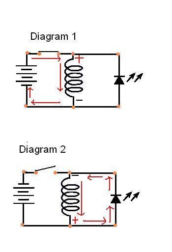
                      Here is Tinman's circuit (Almost identical to my manual again!) that goes with the trace. It has some similarities to electric motor operation, in particular Edison style. What's important is it shows the polarity flipping with the switch. Note that what is not shown clearly is that in diagram 1 the battery voltage is + on top with the coil + fighting it (CEMF). The battery on diagram 2 is out of the circuit and doesn't matter. It curious that he has reversed the battery diagram which could be confusing, but it is inconsequential.


                      Looking at the declining flyback pulse. the coil is now acting like a source. So in a sym motor all coils are interconnected, and the Coil CEMF fights the battery. This negative pulse is disconnected in the the asym motor.

                      Sound right Ufo?
                      Last edited by sampojo; 01-11-2016, 05:35 AM.
                      Up, Up and Away

                      Comment


                      • starting work on my Baldor

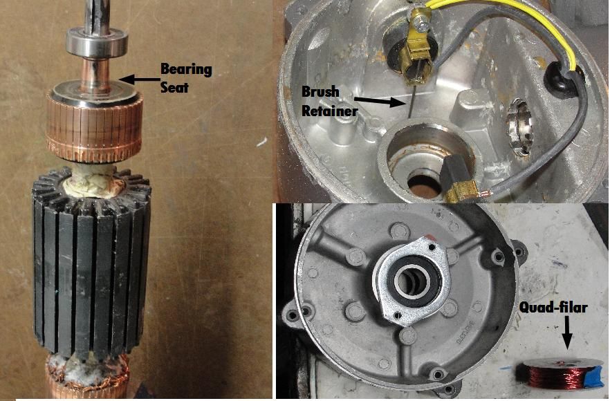
                        planning multifilar with 4 30ga strands, figuring about 25-30' per coil, with 20 coil groups.. Approximates the 19ga wire I took off, about 450'. I will try to put a little more wire on than I took off, although the rotor was stuffed when I dismantled it. Ufo helped with this wiring diagram a while back.


                        Here is the motor redesigned for assymetric operation, posted before.


                        I got some time on my hands again.

                        What I am not sure of is, do I wind CW or CCW? I guess I need to do it the same way as my GM window unipolars, which I ought to have written down or reverse engineer.
                        Last edited by sampojo; 02-18-2016, 03:29 AM.
                        Up, Up and Away

                        Comment


                        • Great!

                          Originally posted by sampojo View Post
                          planning multifilar with 4 30ga strands, figuring about 25-30' per coil, with 20 coil groups.. Approximates the 19ga wire I took off, about 450'. I will try to put a little more wire on than I took off, although the rotor was stuffed when I dismantled it. Ufo helped with this wiring diagram a while back.


                          Here is the motor redesigned for assymetric operation, posted before.


                          I got some time on my hands again.

                          What I am not sure of is, do I wind CW or CCW? I guess I need to do it the same way as my GM window unipolars, which I ought to have written down or reverse engineer.

                          Hello Sam, great to see you as to know you also have some time now!

                          That would be an interesting motor when finished, am sure off.

                          Now remember that the terms CW or CCW are completely relative and dependent from the reference point you are setting your watch/clock...

                          For example take a look at this old diagram when we were winding N-S Pairs, but just focus on the North/Blue side:

                          [IMG][/IMG]

                          Normally our reference point has always been the side of shaft where we are connecting to take power off, remember?

                          [IMG][/IMG]

                          Above same image without the hand reference method.

                          So let's say you will start from the positive(+)commutator, which, at the same token is where power take off Shaft is, meaning on graphic, the top starting point (1). So the North Pole would be aiming towards screen, and if you set your watch with the clock needles shaft also pointing towards screen, then it would be a CW winding. However, if you set the watch shaft aiming away from screen...then that same winding direc tion would be CCW...see why it is all relative?

                          To play safe just do one set of windings first hooked to both comm elements...then power up coils with a small battery source and read outward magnetic orientation on both cores...

                          Hope all this free time will allow you to complete the whole thing...it seems you have all the mechanical structure already finished...so it is just winding and connections to commutators, then fire it up...


                          Kind regards


                          Ufopolitics
                          Principles for the Development of a Complete Mind: Study the science of art. Study the art of science. Develop your senses- especially learn how to see. Realize that everything connects to everything else.― Leonardo da Vinci

                          Comment


                          • Rotation direction confirmation

                            Hi Ufo,

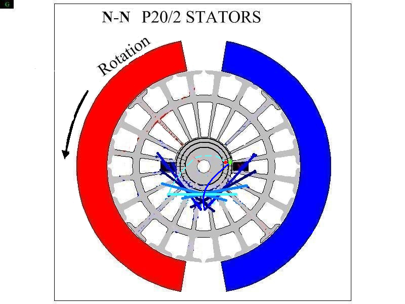
                            I want to make sure I get the polarity and direction of rotation in agreement with option (1) reference of your winding direction diagram. I converted your right hand rule diagram to a unipolar representation and then included my P20 diagram to try to nail the direction of roation. So clearly a N-pole coil will repel from the N magnet and attract to the S magnet. The green (+) and red (-) dots are also shown on the motor diagram commutator, which the convention established is the rear commutator is the inner ring.

                            I believe I have the direction of rotation wrong on my previous P20 winding diagram, which has been corrected below. Here is what I have put together to make it clear to me.


                            Ufo, please confirm if my diagram has the motor rotation correct now.

                            Would you consider this motor would then operate in "repulsion" mode or attraction mode? (repulsion should use less amperage?)
                            Last edited by sampojo; 03-01-2016, 04:22 PM.
                            Up, Up and Away

                            Comment


                            • @Sampojo

                              Hello Sam,

                              Sorry for taking so long, I've been swamped...

                              It seems you've got it right friend...except for the wire going to the red or green dots in right diag, can't see it that clear, sorry.

                              I have made another diagram for your set up below:

                              [IMG][/IMG]

                              Hope it looks better now.

                              So the way I see it, you start from top commutator (positive), then go down from the first core element to left (CW if you put watch/clock right next to core elements to be wrapped). Then you will obtain a North facing out towards stators, like I have shown on diagram.

                              The right Image is for Pairs of all North Coils, in series...

                              Please, let me know if it is clear now.


                              OK, in Repulsion, Motor will consume more amperage than in Attraction Sam, and you could change from Repulse to Attract just by changing the firing order timing, in order that coils fire up (energize) closer to attract stator (South in your case) than repulse one (North)...remember our "Neutral Positioning" where Main Bisector is right in between both stators?...well just move the firing sequence a bit more towards attracting South...that is it.


                              Thanks for keeping your faith on this Machines, Kind Regards Friend.


                              Ufopolitics

                              EDIT: Could not reply directly to your post, so had to use New Post for it to work...
                              Last edited by Ufopolitics; 03-05-2016, 02:04 AM.
                              Principles for the Development of a Complete Mind: Study the science of art. Study the art of science. Develop your senses- especially learn how to see. Realize that everything connects to everything else.― Leonardo da Vinci

                              Comment


                              • P66 motor

                                Greetings:

                                At long last, after several hacks at winding ...... the P66 armature is ready to go to a 'Real' motor shop for tweaking and vacuum pressure impregnating.

                                I have two P56 motors waiting in the wings, and I may modify one of those. So, what is the 'final latest and greatest' winding config for the P56? (I have all those posts in my 'UFO motor notebook' somewhere, but would rather ask to see if there are any updates.)

                                Pics attached, and will post more pics when the armature come home for final assembly.

                                glen
                                Attached Files

                                Comment

                                Working...
                                X