Take 2 on designing in the motor rotation
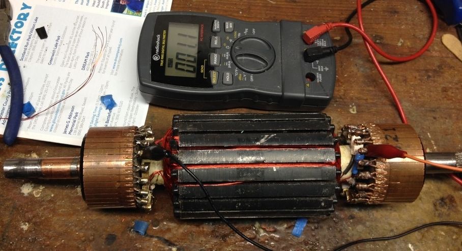
Glen, sweet looking rotors!
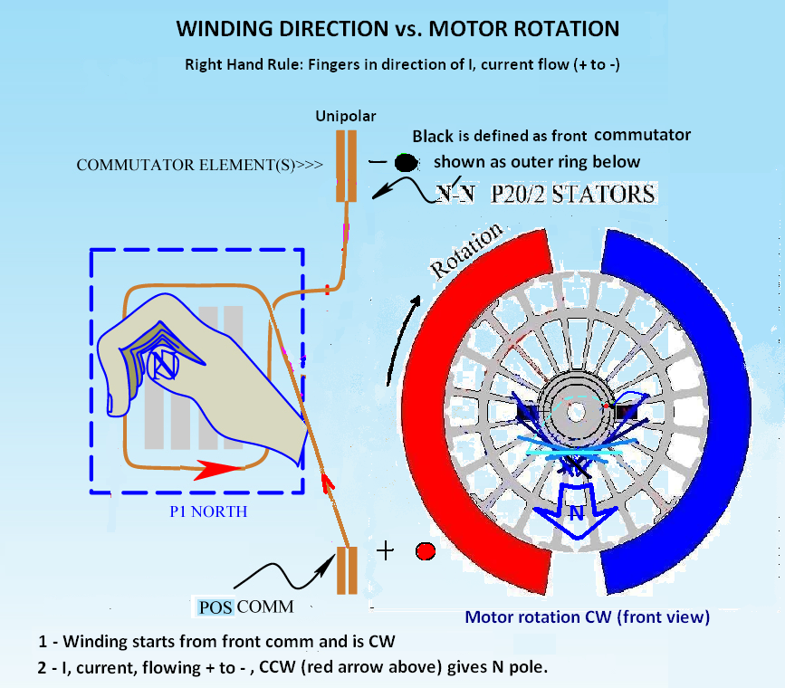
Redid my diagram as best I could, and this is how things came out. So I think to get a motor to rotate CW with this magnet arrangement, I need the + terminal at the rear and the windings to be mechanically wrapped CW, starting from the front comm element. Outer commutator ring would be the front of the motor.

I think I would prefer to have the front of the motor defined as the positive connection however. In that case the winding would start at bullet 1 and be CCW, and the geometry of starting the winding where the dark blue wire originates from the black dot on the outer comm changes, going to the other side of the line representing that specific sub-coil. In winding, I believe I must end up on the lightest blue single coil on top as the last coil wound. OK clear for me now I think...
Glen, sweet looking rotors!
Redid my diagram as best I could, and this is how things came out. So I think to get a motor to rotate CW with this magnet arrangement, I need the + terminal at the rear and the windings to be mechanically wrapped CW, starting from the front comm element. Outer commutator ring would be the front of the motor.

I think I would prefer to have the front of the motor defined as the positive connection however. In that case the winding would start at bullet 1 and be CCW, and the geometry of starting the winding where the dark blue wire originates from the black dot on the outer comm changes, going to the other side of the line representing that specific sub-coil. In winding, I believe I must end up on the lightest blue single coil on top as the last coil wound. OK clear for me now I think...


 so time is a factor. Meanwhile the tankless water heater needs refurbed and cleaned, new plumbing...


Comment