Announcement

Collapse
No announcement yet.

My Asymmetric Electrodynamic Machines

Collapse
X
 
  • Filter
  • Time
  • Show
Clear All
new posts

  • Midaztouch
    replied
    Originally posted by HuntingRoss View Post
    [IMG][/IMG]
    Hi Mark

    We haven't used one comm. What are you trying to demonstrate?

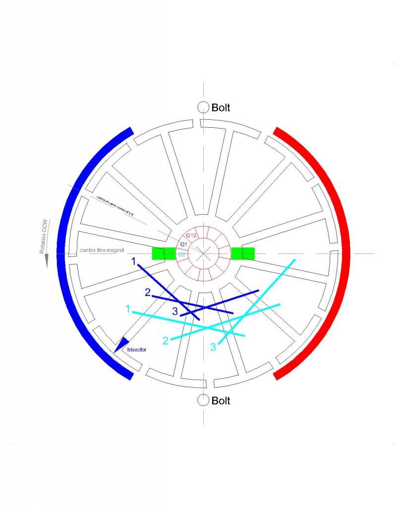
    From your diagram, the max density is at the bolt. That would make the motor very weak. Instead of using the lap winding, try using NN pairs. Set the bisector of the coil closer to the Stator bisector.


    Midaz
    Leave a comment:


  • HuntingRoss
    replied
    Timing diagram for the one comm asym motor

    [IMG][/IMG]

    Leave a comment:


  • HuntingRoss
    replied
    Further tests

    Increasing the resistance of the lead wire to the motor body solves the auto start problem...and...running at 10.34v PSU no load -

    9.05v @ 9.87A @ 11,500 rpm and there is virtually no useful torque which is to be expected.

    Checked the armature after that many revs and everything is still in place.

    My guess for the OEM wire gauge is 0.5mm...calculation from the figures above puts the wire at approx 0.07 ohm/m which looks like 0.53mm or 0.56mm gauge.

    mark

    Leave a comment:


  • HuntingRoss
    replied
    Asym motor with ONE commutator

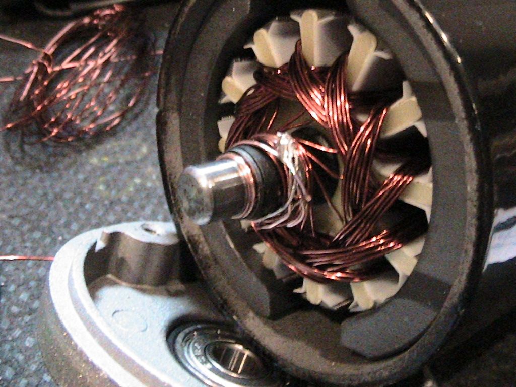
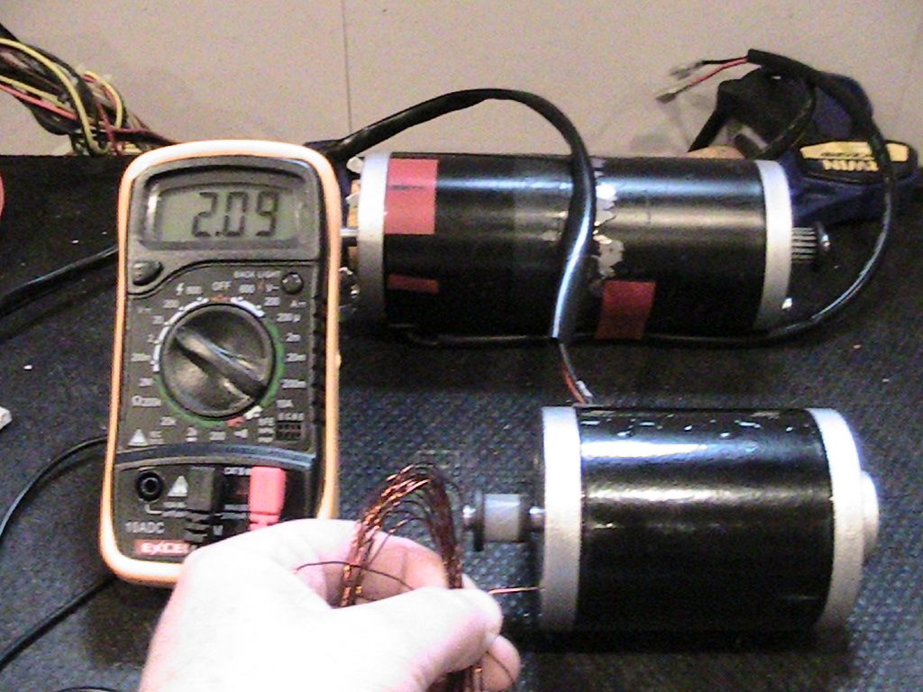
    So I stripped one of my new 24v 120w scooter motors to see if I could do a quick and dirty proof of one comm operation.

    OEM figures.
    Resistance -
    Leads 1.4 ohm
    Motor + Leads 4.6 ohm
    Motor (total 12 pole) 3.2 ohm
    Motor (6 pole) 1.6 ohm
    Longest coil length 3.7m

    I played with the timing on this motor pushing the G1 Coil 1, one pole further away from the north bisector.

    New figures.
    12 groups. 3 coils per group. 2 turns per coil.
    Two turns made it very quick to wind with an expected high amp draw.

    Connected to PSU - no load 5.39v.
    4.86v at 4.85A @ 2990 rpm with 2.05v at the output lead.

    So things to note.

    The bottom of the groups are all connected together and bonded to the shaft.

    The timing has affected the auto start of the motor...or maybe there are insufficient turns per coil...I don't have enough experience to know which one or both are responsible.

    It's a very easy build as it all fits within the OEM body and there is no second comm to fit. This took me 5 hours to strip build and test.

    The photo shows me grounding the body to start the motor.

    This method loses the ability to add the battery voltage to the output voltage as reported with the two comm motor. I suspect this is because the collapsing coils are lost to the shaft connection.

    Otherwise it seems to operate as a two comm asym motor.

    [IMG][/IMG]

    [IMG][/IMG]

    keep hunting

    mark

    Leave a comment:


  • HuntingRoss
    replied
    'Beast' - Field test #2

    With the 'beast' wired directly to the batteries via a 40A power relay and protected by a 20A fuse I report the following -

    The starting temp of the motor body was 15.3 C rising to 28.6 C after 3 laps of approx 400 yards each.

    The run out is on a slight down gradient and the scooter was noticeably faster than the OEM. On the return leg the scooter slowed progressively to a stop before reaching the starting point. This was better than field test #1 where it popped the circuit breaker long before returning to the start position...but contrast with the OEM that did this circuit with no appreciable loss in performance.

    On returning home the beast was bench tested to see if any fault(s) had given rise to the problem -

    Rear wheel off the floor at full throttle is 965 rpm @ 4.5A rising to 16.8A stall speed.

    Swapped out for the OEM motor -

    At full throttle is 624 rpm @ 1.2A rising to 15.7A stall speed.

    For some inexplicable reason the 'beast' can not translate the superior bench test results to the ground.

    I checked continuity again. No faults.

    I checked the 12 groups for resistance with my new meter and they all checked out at 2.3 - 2.4 ohms

    I have ordered equipment to rig a prony test and will report results in due course.

    Not so happy hunting

    mark

    Leave a comment:


  • Midaztouch
    replied
    UFO

    Thank you for your excellent explanation and diagrams. They are very clear and easy to follow. Yes, I understand the MAX Amps at/near TDC° Repulsion for a split second from a static position or stalling the motor to a dead stop.


    Sorry my thought and questions were not clear in my last post. I will try to clarify using your diagrams above

    This is my case...

    My thought was to set the timing as close as possible to 0°TDC "towards rotation" at the NSB/repultion . This would leave enough room to add one more coil per group. TDC° will bring the Max Density closer to the NSB, creating more torque.

    Instead of 3 coils in group1, have 4 coils in group1. This would increase the volume area/through out angles of the coils magnetic fields of G1and G2 magnetic fields combine. Also 4 coils would increase the strength of Max Density(over 25% vs 3coils??) when G1and G2 magnetic fields are overlapped/combine. Since the magnetic area is larger, it will be closer to the SSB/attraction... Further increasing the torque and RPMs without creating magnetic drag from SSB.

    *How do less turns per coil, for 4 coils per group, effect performance?

    *Does TDC° timing causes NN motors to reach absolute highest RPMs?

    *Do the attributes of setting the timing as close as possible to TDC outweigh the increase in AMPs?

    *Do the AMPs lower and stabilize at high RPMs because of space & time(timing) under load in NN Asymmetric Motors?

    *If the motors are set like the way I'm proposing, would you only have to adjust voltage to find the sweet spot for racing needs?

    *How does TDC° timing effect the gen action for producing energy?

    *For drag racing, could we reverse the polarity on the gen brushes to create a motor only or should we just disconnect the gen brushes?


    Sorry for so many questions, please answer what you can. Just trying to get a better understanding or what I can get away with! lol

    Keep it Clean and Green
    Midaz
    Last edited by Midaztouch; 10-25-2014, 01:30 PM.

    Leave a comment:


  • HuntingRoss
    replied
    For the time being

    Hi UFO

    It wasn't clear in my last post, but the intention is to address the timing/amps draw in the next motor rebuilds and not this one.

    If this is the max power timing for this build of this motor then I will go with that.

    The brush boards are mounted on the motor end caps, timing adjustment would be by rotating the end caps given by the limits of the fixing bolts positioned between the north/south magnets.

    My uncertainty would be how to rotate both end caps to the same position to ensure perfect alignment...failing that...timing is defined by how inaccurately the two boards are positioned relative to each other. In practice I feel this margin of error is probably quite small.

    best regards

    mark

    Leave a comment:


  • HuntingRoss
    replied
    Further field test pending

    Hi UFO.

    Thanks for the update and graphics in response to Midaz's question.

    I have 3 more motors on order. One is a 450w geared motor which I'm going to try and drive and old petrol grass kart...the other two are similar baby motors to the scooter.

    The two baby motors are going to be for quick tests to see which setups work best and finally to try and maximise copper density and resistance. I will also try and match or better the OEM resistance this time.

    The field test this weekend will be on the scooter with 'beast' re-installed BUT with all OEM electronics bypassed. It is now wired through a switch to a power relay straight to the motor...ON/OFF. Circuit protection is a 20A fuse which can be swapped out to find the maximum draw if required. The test pilot will have to sit the first run on the side lines as I make sure it is safe enough for her to try.

    This will demonstrate immediately if the controller is the issue as it will either put all the power down the gradient or not.

    I have found a UK website that sells most scooter parts I need including a 500w controller for only £15...much better than the US mail order option and waiting...I hate waiting.

    Updates to follow.

    mark

    Leave a comment:


  • Ufopolitics
    replied
    All North Alignment...

    Originally posted by Midaztouch View Post
    @UFO

    A few weeks ago I asked this:

    Setting the "Timing" of coil one(C1) of group one(G1) at TDC of the bi-sector of the magnetic or as close as possible after the mag bi-sector. Plus, winding one more pole.

    Will this increase the Amps?
    If so, Is the extra torque worth the extra amps?
    Do the RPMs increase?
    To me this seems as though this is the ideal setting. If not, why?

    Keep it Clean and Green
    Midaz

    Hello Midaz,

    Ok, first, We do NOT align at TDC (Top Dead Center) of the two Bisectors (Rotor and Stator)...We align CLOSE to the Stator Bisector towards the rotation sense we desire, say 10º to 20º based on Coil 1...Now, Coil 1 (1) is given as an "Accurate Mathematical Positioning" in order to have a close/clearer view when we are setting timing...BUT, in reality it is NOT just based on Coil One (1)...take a look below:

    [IMG][/IMG]

    Using the 12 Pole Motor as Mark (Hunting Ross) have...as this will serve for his learning...I have set the point in time where two Groups are being fired, in this case G1-G2.

    I have set NSB (North Stator Bisector) as well as SSB (South Stator Bisector).

    So here is what happens in reality...

    When We have a Group of Overlapped Coils, the CENTER COIL (in this case Coil Two (2)) is where the MAX DENSITY concentrates...Now, here We have Two Groups being fired, so a "Virtual Center" is originated right between the Geometrical Center that those Two Groups configure as shown above.

    If We look at the Angles in this Interaction, between Both Stators Bisectors and the MAX DENSITY SPHERE (Yes it is a 3D Sphere Volume, and We can not see it but we can "feel it"... if we get two Concave and Convex same polarity magnets and try to roll them while getting them closer...and following rotation along curves...we feel how "ball moves" in an "in between" fashion between the two virtual centers or bisectors)

    Now, as Rotation keeps going We have just ONE GROUP being fired:

    [IMG][/IMG]

    We notice the Max Density Sphere is about the same place...except this time is right on center of BG1(2) (Bisector Group 1, Coil 2)

    And...if We move the Brushes a bit towards rotation...then we have:

    [IMG][/IMG]

    In this case -for clarity- We are just firing One Group (G1), and We notice the Sphere is at the center between both Stators Bisectors (N-S)...and this is where a 50/50 Setting is, where Repulse and Attract Forces are of equal distances, equal strength...on previous posts , when doing N-S Pairs, I have written a setting in a "NEUTRAL ZONE"...and this is the same thing, but applying to All North.

    Understanding this, then I will answer your question(s).


    Will this increase the Amps?
    Yes, it will increase Amp Draw if we align AS CLOSE AS POSSIBLE based on REPULSION MODE. The Motor would be very strong, and speed over the limits as well...but sacrifice is that we use a lot of energy to achieve this.

    So, aligning to displace that Max Density Sphere more towards the South Stator (Attract Mode), we will reduce Amp Draw...but consequently, also reduce Speed and Torque...Then We will have to look for that "Sweet Spot" in between "Both Worlds" that fulfills our demand based on our application(s).

    And every case is different on applications scenarios, for example in Hunting Ross case...when his Daughter adds her weight, standing on top of scooter, plus the steady friction between tires and road, adds too much load/amp draw... causing to open the breaker because of Amps increase beyond spec's. I am pretty sure this issue would be resolved by adjusting brushes towards a more "relaxed" attract mode and less Repulse mode.

    When We were testing the Imperial on N-S Pairs, there were some replications here (Hitby13KW) that were running "too weak and slower", and I found out the factory Stators settings on the housing were NOT as I have displayed on my Diagrams as mine came in from factory...but "rotated" about 90º, and, if We do not check/define WHERE are our North-South Stators are positioned, related to Brush positioning...then we could be setting Motor on Attract Mode, BUT in a HIGHER PERCENTAGE than Repulse...this delivers a too weak Motor...but, happily very low amp draw...

    Conclusion...the "Ideal Setting" is different for every model, based on its structure, application, etc...We MUST find that sweet spot/ideal setting...in our Timing, where it will fits our application.

    Midaz: I did not understand the underlined part below:

    Plus, winding one more pole.
    Winding One more Pole on top of the designated per Group?

    Anyways, a couple more things...

    1- There are also other opposite (South) magnetic fields generating simultaneously at 180º apart per each Group being fired North...and being "assisted" by the naturally reversed Coils at Output, exactly 180º apart...I did not display this part for sake of clarity and simplicity... but this is one of the reasons why our Asymmetric Machines -basically the All North- are so powerful and fast at the same time.

    2- The "Sphere" of Maximum Density is NOT all of the Magnetic Field definition in Space...the Magnetic Field Spectrum propagates beyond this...surrounding the first Coil (1) and ending also beyond and around the Third Coil (3)...The Sphere as Magnetic Fields are "flexible/elastic"...and we can compress its shape/volume making it look like an Elliptical Geometry in 3D...


    Best Regards


    Ufopolitics

    Leave a comment:


  • Midaztouch
    replied
    @UFO

    Was thinking about just timing adjustment could be "too much towards repulse" rather than 50/50...or more towards attract...and I know you have very clear the concepts of Bisectors and the right firing positioning.

    But what happens is as follows...if you are set too close to North Stator Bisector, then your amp draw will increase top max...and the further you fire your groups more towards an attraction (or closer to South Stator)...the lower your amp draw...and at heavy loads am saying here.


    Ufopolitics
    Ufo

    A few weeks ago I asked this:
    Setting the "Timing" of coil one(C1) of group one(G1) at TDC of the bi-sector of the magnetic or as close as possible after the mag bi-sector. Plus, winding one more pole.

    Will this increase the Amps?
    If so, Is the extra torque worth the extra amps?
    Do the RPMs increase?
    To me this seems as though this is the ideal setting. If not, why?

    Keep it Clean and Green
    Midaz

    Leave a comment:


  • Ufopolitics
    replied
    Repulse to more Attract...

    Originally posted by HuntingRoss View Post
    Hi UFO. Thank you once again for the in depth and technical response. I feel like such a fraud as this is way past the edge of my experience but I will risk burning my fingers in the name of progress.

    One thing occurs to me though. Is there a place for going old school and simply fitting a rheostat type throttle and accept some loss in heat ?

    5K Ohm Electric Scooter, Bicycle, and Go Kart Throttles - ElectricScooterParts.com

    No electronics to fry in the setup requiring kill switch ?

    Comments in red below.
    Hey Mark,

    Was thinking about just timing adjustment could be "too much towards repulse" rather than 50/50...or more towards attract...and I know you have very clear the concepts of Bisectors and the right firing positioning.

    But what happens is as follows...if you are set too close to North Stator Bisector, then your amp draw will increase top max...and the further you fire your groups more towards an attraction (or closer to South Stator)...the lower your amp draw...and at heavy loads am saying here.

    So, give it a try to play with the proper settings...


    Regards friend


    Ufopolitics

    Leave a comment:


  • DadHav
    replied
    Originally posted by HuntingRoss View Post
    Hi John

    It's the only way I could describe stepping up 10v to 17v. I have no idea whether it did it efficiently or not. With my limited understanding (and a little knowledge IS supposed to be dangerous...or so THEY say) connecting one brushed group through the other brushed group as if they are all connected on the shaft struck me to be like center tapping a coil...it certainly drove the OEM motor very well.

    Anyhoo, I'll keep my head down and dodge the bullets.

    And I do appreciate the many tips to test the two motors together...I have an old aluminum fan knocking around somewhere which should put some nice drag on the shafts.

    mischievously hunting

    mark
    Hi Mark a fan blade will alway give you the same dependable amount of resistance between both test subjects and that's a good inexpensive device in my opinion. On the transformer sinopsis. Without a designated coil or set of coils separate of the two you call center tapped I'm not so sure. Think of it this way. You have one coil that already has the run voltage across it and another coil being energized from the magnets that is in series, so you're adding the generated voltage to the battery voltage which is already there. When you add a load across the both you are probably in a situation where part of the load is on the battery and the other part on the generator coil. Dont forget the generator coil is on the same set of laminations so it must be receiving some sort of transformer effect, as a matter of fact each of the coils must receive something from the other as fields collapse or what ever. that's why this motor is different than running a separate generator driven from the shaft of the motor. I'm sure you know when you connect your motor and generator coils in series and run them as a motor, things change. You will lose RPM's but your motor should run strong with low current draw. It's almost like starting off in low gear with all legs of the stator in motor mode. To bad you can't rig a switch to change options while driving right? My opinion only. I've presented a few videos where you can see the effects i mentioned on a scope but it is with brushless motors and really dramatic. Good luck Mark, I'm sure UFO will help you get going.
    John

    Leave a comment:


  • HuntingRoss
    replied
    No claims of efficiency

    Originally posted by DadHav View Post
    Whoa, on your step up transformer comment. You'll have to discuss that with UFO and the other members. My explanation would take way to long to lay down at this time and I would probably get in trouble again. I will say this: Keep in mind the ultimate goal. Any potential above the input, no matter how you obtain it, whether it be as radiant, generated, from the vacuum, coupled between input and output coils, defying Lenz or any other method has to assist in bringing down the current for the system to run at an energy savings level. To obtain this I believe the output when used should probably have to operate without drawing extra current or slowing the motor down. I don't know if I stayed out of trouble with that or if my thoughts are correct but it's what I would like to see. I have not seen it myself with a brushed motor.
    John
    Hi John

    It's the only way I could describe stepping up 10v to 17v. I have no idea whether it did it efficiently or not. With my limited understanding (and a little knowledge IS supposed to be dangerous...or so THEY say) connecting one brushed group through the other brushed group as if they are all connected on the shaft struck me to be like center tapping a coil...it certainly drove the OEM motor very well.

    Anyhoo, I'll keep my head down and dodge the bullets.

    And I do appreciate the many tips to test the two motors together...I have an old aluminum fan knocking around somewhere which should put some nice drag on the shafts.

    mischievously hunting

    mark

    Leave a comment:


  • DadHav
    replied
    Fan?

    Originally posted by HuntingRoss View Post
    I absolutely agree John. I'm looking for the easiest method to test and prove one against the other. The prony test may be the simplest way to do this.

    This is a method for me to understand a science I have never studied and so I can apply it to something I actually need.

    The thing I find interesting about this asymm motor is it operates as a motor/generator AND if I understand my results correctly...


    A step up transformer.

    That has to be pretty cool all in one package.

    happy hunting

    mark
    Mark, if nothing else you can go to a junkyard and find a small plastic radiator fan of some kind. Jury rig an adapter to get it on the shafts and you're set to go. Your modified motor should draw less current than the OEM when running at the same RPM or it won't likely be an advantage, conversely if you have both motors drawing the same current you would hope to have a higher RPM on your modification. The higher speed would definitely indicate an ability to handle more load for the same watts as the OEM. Anyway just another suggestion. Whoa, on your step up transformer comment. You'll have to discuss that with UFO and the other members. My explanation would take way to long to lay down at this time and I would probably get in trouble again. I will say this: Keep in mind the ultimate goal. Any potential above the input, no matter how you obtain it, whether it be as radiant, generated, from the vacuum, coupled between input and output coils, defying Lenz or any other method has to assist in bringing down the current for the system to run at an energy savings level. To obtain this I believe the output when used should probably have to operate without drawing extra current or slowing the motor down. I don't know if I stayed out of trouble with that or if my thoughts are correct but it's what I would like to see. I have not seen it myself with a brushed motor.
    John

    Leave a comment:


  • HuntingRoss
    replied
    Originally posted by DadHav View Post
    If adapting your motor to the scooter for testing has become to complicated to be practical you might want to go back to square one and try testing to see if the modified motor will actually perform better than an OEM.
    I absolutely agree John. I'm looking for the easiest method to test and prove one against the other. The prony test may be the simplest way to do this.

    This is a method for me to understand a science I have never studied and so I can apply it to something I actually need.

    The thing I find interesting about this asymm motor is it operates as a motor/generator AND if I understand my results correctly...

    Originally posted by HuntingRoss View Post
    PSU Volts no load = 10.32v.

    Voltage between V2 in (-ve) bottom comm and V2 out (+ve) top comm = -7.40v.

    Voltage between V1 in top comm and V2 out top comm = 17.40v.

    Motor speed = 2186 rpm.

    Under this test one can either take out 7.40v or 17.40v if desired AND take the torque from the shaft.
    A step up transformer.

    That has to be pretty cool all in one package.

    happy hunting

    mark

    Leave a comment:

Working...
X