Originally posted by Ufopolitics
View Post
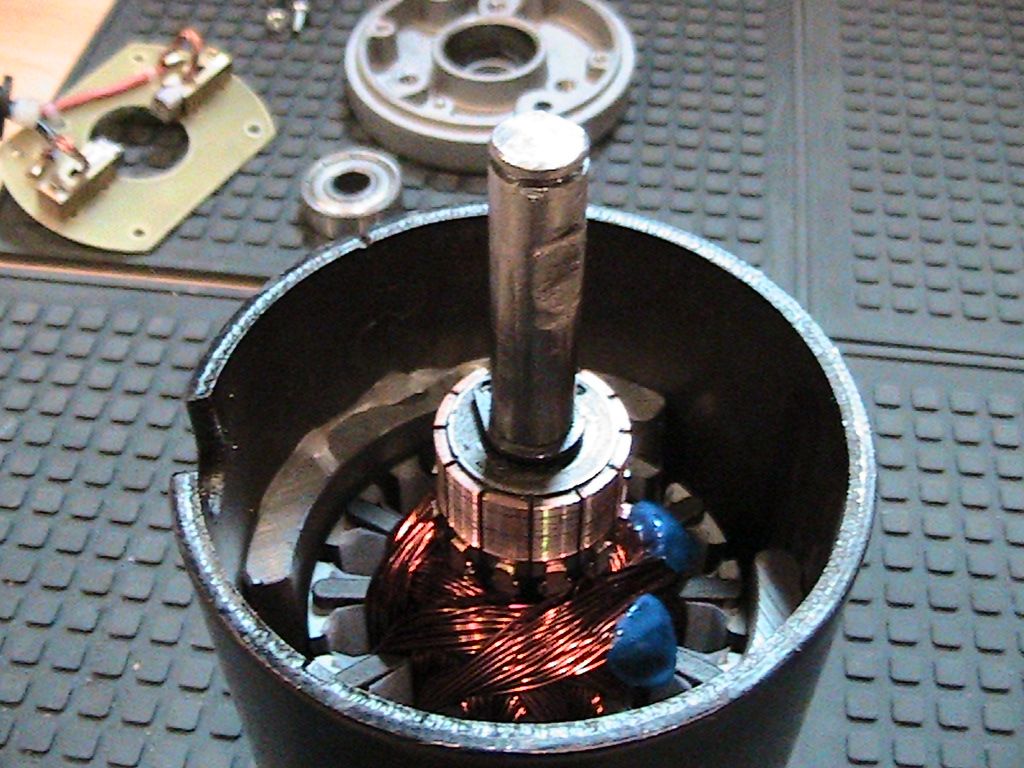
Here's a few photos to try and describe a little better -
[IMG]
 [/IMG]
If the stator magnet in view is the north magnet then the top edge is north and the bottom edge is south. When the two casings are turned to join, the two north magnets are facing south to south. I checked the field (?) with a magnet lowered down the axis and there is an amount of disruption at the adjacent edges but it is minimal and not much more than the field variation across the face of the curved magnet nearing the centre. So I'm going t bash on with this method.
[IMG]
 [/IMG]
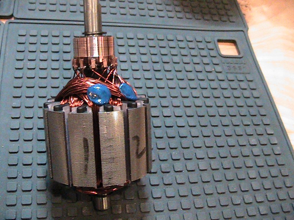
You can see in this photo the rear shaft is too small to fit a commutator. The blue dots appear to be a hot melt glue to stabilise the windings (?) they seem to serve no other purpose. The poles are already numbered.
Thanks. mark.





Leave a comment: