If this is your first visit, be sure to
check out the FAQ by clicking the
link above. You may have to register
before you can post: click the register link above to proceed. To start viewing messages,
select the forum that you want to visit from the selection below.
Yes, there has been a lot of information disclosed over the last 4months about the A1 Mo-Gen. Take your time with your testing. It looks like people's kits will start to arrive in a few weeks. I'm here if you need me....
@ Team, a diagram for John please.
Keep it Clean and Green
Midaz
Richie, I would just like to address a few things that pertain to the last three videos before anything else. I think one was resolved and for my own experience I'd like to try some things regarding the other two. You don't have to bother anyone to much about a diagram just a simple yes or no to my interpretation is OK. My observation is the bulb was lit with a path from the battery through one of the coils through the filament and then back to the battery. That leaves me with not knowing how anything else is effecting the demonstration as it pertains to just the bulb. I think lighting the bulb is not as important as the motor increase in speed. I have a theory but will hold off until I know I saw the connections right. Of course if people think the bulb is being lit from the generator of the motor then that's a different story. By the way I did use 600 ma of light bulbs and tested the ns rs motor. I had instances that the voltage went above base line and most below. I have to look at what UFO's video looked like at that time of test, but I might have had similar.
John
Richie, there's a lot of information to go through. You have to give me some time to test a few things. Remember anything I said above may not apply if assessed the connections wrong. It would have been easier it UFO would have had a drawing on the video but that's not a complaint. I looked at the other cap charge video and have a few things to say about very basic things to expect when charging batteries and capacitors but I will also try a few tests first. Glad you had a good time at the beach. My family is in their 40's now. Our time at the lake is nothing but work. The deer have eaten everything that was standing just about and it's an acre lot. I'll bet Cornboy knows what it's like to loose things to predators and weather.
Take care
John
John,
Yes, there has been a lot of information disclosed over the last 4months about the A1 Mo-Gen. Take your time with your testing. It looks like people's kits will start to arrive in a few weeks. I'm here if you need me....
Thank you for accepting my invitation. I hope that you & your family plus the kids(dogs) had a great time at the lake.
From what I recall, the posts and the replication videos in the past, do not apply to this all north winding. Some replicators in the past were having trouble setting the timing. That gave low motor performance/inaccurate data.
Also in this vid was when we first started to get smooth clear readings from the generator output. It showed what you put in is what you got out, about 1:1 ratio. This is very important because it leads us to the four stator motors/generators. The four stators will have one input and 3 outputs. By having 3 outputs do you think that the amp draw will increase or will be tripled??
Yes about 600ma is correctDo you think that if you had a stronger bulb the RPMs would have increased, stayed the same or decreased?
What I gather from this statement is that the RS NS should do similar to the all North.
John, I invited you here! I assure you that no one from my team will verbally abuse you and/or attack you! We are all here for the truth. We are at a serious point with our testing. You are a retired CHEIF electrical engineer. Your time is very valuable for us at this juncture.
@Team, please provide John a diagram.
Dadhav, again thank you. If you have a little more time, could you expand how or why the energy consumption drops with the all north winding? ... Below, I have stated my opinion/scientific guess why the drop in energy consumption.
After the NS vs All north, testing was done adding super caps https://m.youtube.com/watch?v=-Afl9m...0YnD2b5zasXXng. Any takers to have constructive dialogue with me on the super caps vid? If possible, I would like to talk to Russ.
@All, One thing that stands out the most for me is that the energy consumption versus the two motors is drastic. From my experience, the way that the coil magnetic fields and the stator fields interact are completely different from RS 5pole NS and the All North RS 5pole, A1 Mo-Gen. In the A1 Mo-Gen the electrons are not impeded in anyway. It gives you a smooth express electron flow. I believe that this is why the energy consumption drops and the RPMs are increased with the A1 Mo-Gen compared at the same wattage as an off the shelf unmodified RS motor and modified RS north/South motor. What are your thoughts?
For me, I'm all about the overall system performance, OSP. I'm looking for a system that has a lower energy consumption with and without an electrical/mechanical load = more efficient/more range less batteries... A motor that does not overheat = no need for a cooling system for the motor/no extra weight. Also, an improvement over regenerative braking = charging while driving is less weight. Less parts without compromising performance gives you better quality control, that leads to better reliability. Ultimately giving an overall higher customer satisfaction. Less over all weight and dollar$ for dollar$ are part of this equation.
OSP is the key. There is no need to bump heads about over unity. At this moment, I'm focused in on, available off the shelf technology VS an improvement, the A1 Mo-Gen... Is the torque and increased RPMs in the A1 Mo-Gen competitive? Is the A1 Mo-Gen a viable alternative over current technology? This is my current dogma.
Keep it Clean and Green
Midaz
Ps. Today was my first day at the beach this year. My family and I had a great time! Enjoy!!!
Richie, there's a lot of information to go through. You have to give me some time to test a few things. Remember anything I said above may not apply if assessed the connections wrong. It would have been easier it UFO would have had a drawing on the video but that's not a complaint. I looked at the other cap charge video and have a few things to say about very basic things to expect when charging batteries and capacitors but I will also try a few tests first. Glad you had a good time at the beach. My family is in their 40's now. Our time at the lake is nothing but work. The deer have eaten everything that was standing just about and it's an acre lot. I'll bet Cornboy knows what it's like to loose things to predators and weather.
Take care
John
Hello Richie thanks for inviting me to offer an opinion. First of all let me answer by asking some questions again.
Is the all north wind the same as when some of us made a mistake interpreting the winding diagram at the beginning of all this?
Hi Dadhav
Thank you for accepting my invitation. I hope that you & your family plus the kids(dogs) had a great time at the lake.
From what I recall, the posts and the replication videos in the past, do not apply to this all north winding. Some replicators in the past were having trouble setting the timing. That gave low motor performance/inaccurate data.
OK what did I see in the video. Please correct me anyone if I'm wrong.
1. An improved winding on the standard RS setup.
2. The test connection was putting the two coil sets in series which dropped the KV of the motor and as a result the speed decrease by about half but the torque probably almost doubled.
3. The automotive bulb was attached to the wires on one side of the motor and the jumper on the front or back end wire lugs.
We all could see what the test results where. The tests seem to show a motor that runs better with new wind.
Also in this vid was when we first started to get smooth clear readings from the generator output. It showed what you put in is what you got out, about 1:1 ratio. This is very important because it leads us to the four stator motors/generators. The four stators will have one input and 3 outputs. By having 3 outputs do you think that the amp draw will increase or will be tripled??
OK because the results looked interesting I took my old RS motor with the old wind and made the same tests for myself. I didn't have a bulb as big as yours but I had a 12 volt automotive panel light. This bulb draws about 210 ma at 9 volts. Yours in the movie used about 600 ma not 60 ma as you said if I'm not wrong. I'm sure you just had a vocal typo on that though.
Yes about 600ma is correct
Here's a few readings I made through the test.
At 9 volts the motor ran at 14,150 RPM with no bulb load and used 420 ma current draw.
When I attached the bulb as I think you had it in the video the current draw went up to 610 ma. Note the difference in the increase is almost the same as what is seen when the bulb is connected directly to 9 volts without the motor.
Next the RPM check almost didn't change, it measured 14,136 but there is some slight fluctuation in my motor performance because I haven't cleaned the commutator in a long time.
Do you think that if you had a stronger bulb the RPMs would have increased, stayed the same or decreased?
An amp and voltage reading at the bulb showed 8.89 volts across the filament and a current draw of 209 ma.
My conclusion to this test was I duplicated UFO's test pretty close with very similar results. Remember the motor does not have the all north wind.
I had a theory in my mind about this test before even starting so to work on my own idea of what was happening I took two radio shack motors that are unmodified and attached them together with rubber tubing. I connect the motors in series and put the same bulb in the appropriate place and the bulb lit without the motors changing speed. The bulb wasn't as bright because of the resistance in the coil of a motor having twice the copper in the winding.
What I gather from this statement is that the RS NS should do similar to the all North.
Well I could be totally wrong about everything I've done and will take it like a man when you explain it.
John, I invited you here! I assure you that no one from my team will verbally abuse you and/or attack you! We are all here for the truth. We are at a serious point with our testing. You are a retired CHEIF electrical engineer. Your time is very valuable for us at this juncture.
I didn't see a drawing of your experiment with the bulb but what I picture is a circuit on one side of the motor that is in series and made up of the battery, one of the two coils and the bulb.
@Team, please provide John a diagram.
I might miss my guess but I think if you took the magnets out of the motor and it wasn't turning that the bulb would light the same as being on 9 volts, of course with the exception of the drop in voltage going across the winding. Maybe 1.3 ohms or something? I don't think the motor running has any significant effect on the bulb lighting. I'll be looking forward to your explanation.
Dadhav, again thank you. If you have a little more time, could you expand how or why the energy consumption drops with the all north winding? ... Below, I have stated my opinion/scientific guess why the drop in energy consumption.
After the NS vs All north, testing was done adding super caps https://m.youtube.com/watch?v=-Afl9m...0YnD2b5zasXXng. Any takers to have constructive dialogue with me on the super caps vid? If possible, I would like to talk to Russ.
@All, One thing that stands out the most for me is that the energy consumption versus the two motors is drastic. From my experience, the way that the coil magnetic fields and the stator fields interact are completely different from RS 5pole NS and the All North RS 5pole, A1 Mo-Gen. In the A1 Mo-Gen the electrons are not impeded in anyway. It gives you a smooth express electron flow. I believe that this is why the energy consumption drops and the RPMs are increased with the A1 Mo-Gen compared at the same wattage as an off the shelf unmodified RS motor and modified RS north/South motor. What are your thoughts?
For me, I'm all about the overall system performance, OSP. I'm looking for a system that has a lower energy consumption with and without an electrical/mechanical load = more efficient/more range less batteries... A motor that does not overheat = no need for a cooling system for the motor/no extra weight. Also, an improvement over regenerative braking = charging while driving is less weight. Less parts without compromising performance gives you better quality control, that leads to better reliability. Ultimately giving an overall higher customer satisfaction. Less over all weight and dollar$ for dollar$ are part of this equation.
OSP is the key. There is no need to bump heads about over unity. At this moment, I'm focused in on, available off the shelf technology VS an improvement, the A1 Mo-Gen... Is the torque and increased RPMs in the A1 Mo-Gen competitive? Is the A1 Mo-Gen a viable alternative over current technology? This is my current dogma.
Keep it Clean and Green
Midaz
Ps. Today was my first day at the beach this year. My family and I had a great time! Enjoy!!!
Have you had a chance to analyze the NS -vs- all North video? I/We have drawn a lot of conclusions based on this testing. It's the same gauge wire and # of turns. This is why it was said that the all north winding creates a totally different machine. Do you have some ideas about the lower power consumption and the increase RPMs? Also, your thoughts on, why? would the generator action be more defined, would be greatly appreciated.
Keep it Clean and Green
Midaz
Hello Richie thanks for inviting me to offer an opinion. First of all let me answer by asking some questions again.
Is the all north wind the same as when some of us made a mistake interpreting the winding diagram at the beginning of all this? Thats interesting if it's the case. OK what did I see in the video. Please correct me anyone if I'm wrong.
1 An improved winding on the standard RS setup.
2 The test connection was putting the two coil sets in series which dropped the KV of the motor and as a result the speed decrease by about half but the torque probably almost doubled.
3 The automotive bulb was attached to the wires on one side of the motor and the jumper on the front or back end wire lugs.
We all could see what the test results where. The tests seem to show a motor that runs better with new wind.
OK because the results looked interesting I took my old RS motor with the old wind and made the same tests for myself. I didn't have a bulb as big as yours but I had a 12 volt automotive panel light. This bulb draws about 210 ma at 9 volts. Yours in the movie used about 600 ma not 60 ma as you said if I'm not wrong. I'm sure you just had a vocal typo on that though. Here's a few readings I made through the test.
At 9 volts the motor ran at 14,150 RPM with no bulb load and used 420 ma current draw.
When I attached the bulb as I think you had it in the video the current draw went up to 610 ma. Note the difference in the increase is almost the same as what is seen when the bulb is connected directly to 9 volts without the motor.
Next the RPM check almost didn't change, it measured 14,136 but there is some slight fluctuation in my motor performance because I haven't cleaned the commutator in a long time.
An amp and voltage reading at the bulb showed 8.89 volts across the filament and a current draw of 209 ma.
My conclusion to this test was I duplicated UFO's test pretty close with very similar results. Remember the motor does not have the all north wind.
I had a theory in my mind about this test before even starting so to work on my own idea of what was happening I took two radio shack motors that are unmodified and attached them together with rubber tubing. I connect the motors in series and put the same bulb in the appropriate place and the bulb lit without the motors changing speed. The bulb wasn't as bright because of the resistance in the coil of a motor having twice the copper in the winding.
Well I could be totally wrong about everything I've done and will take it like a man when you explain it. I didn't see a drawing of your experiment with the bulb but what I picture is a circuit on one side of the motor that is in series and made up of the battery, one of the two coils and the bulb. I might miss my guess but I think if you took the magnets out of the motor and it wasn't turning that the bulb would light the same as being on 9 volts, of course with the exception of the drop in voltage going across the winding. Maybe 1.3 ohms or something? I don't think the motor running has any significant effect on the bulb lighting. I'll be looking forward to your explanation.
John, You have been away from this Thread for a while now...I don't know if you have been looking at it from an outsider end either...but, based on your comments about my Machines draining High Amperage...Those are "Past News" John...and I remember you did reply here when I was disclosing my New All North Winding Type...and I loaded my Comparison Video Against my own previous creation...the North-South Pairs Type on this VIDEO...
You will be surprised what amount of Amperage this Machine draws when running in this kind of set up...
Ufopolitics
Have you had a chance to analyze the NS -vs- all North video? I/We have drawn a lot of conclusions based on this testing. It's the same gauge wire and # of turns. This is why it was said that the all north winding creates a totally different machine. Do you have some ideas about the lower power consumption and the increase RPMs? Also, your thoughts on, why? would the generator action be more defined, would be greatly appreciated.
Hi UFO and all, just a quick update with where I am up to.
Have just finished planting the years Garlic crop, the rows are 100mt long and I have planted 28 rows this season, enclosed pic's.
All the rows are heavily mulched with material harvested, on farm, with my forage harvester, and placed by hand, the seed is also hand planted.
We are in drought here, luckily I have an endless water supply from an underground bore, and can run a small irrigator 24/7 if needed.
Only trouble is the energy cost to run it,( about $30.00 / night AUD.)
Have just planted yesterday my Wheat crop, on the back of 8mm or rain, it's very late, almost outside the planting window, so fingers crossed.
Now it's just a matter of a bit of catch up work and hopefully I will have some time to wind my all north MAG3 rotor.
Cheers Everyone, Cornboy.
[IMG][/IMG]
[IMG][/IMG]
Hello Cornboy,
Nice pictures!
I wish I could send you some Grey Clouds ...We are getting swamped here with so much rain, day and night!!...
Great, I see MAG3 coming in the show pretty soon then!!
To understand the firing sequences in your diagrams, I started drawing lines between the energizing motor brush set and the centerline of the matching coil set. I was trying to apply the nearest unipolar design of a quad stator, your last bosch rendering. It has the equivalent "2.5 poles angular measurement" for this definition. Translating to a 10-pole rotore would be 1.25 poles.
Very helpful how you make clear the changes in geometry for a 10-pole changes everything. I have showed your diagram re-interpreted with my theta timing angle. To me this is the definitive parameter in wiring your diagrams and helps me see things better. So here it is if it helps anyone else.
Theta angle subtended by green angle
While I tried to reverse engineer the 20-pole bosch diagram erroneously, you show the angle to be 1.5 and a simple 2 subcoil group is necessary!
Thank you very much!
PS almost complete Monster driver board 2 which will make available a PWM system for my 2-stators!!! See other thread.
Hello Joe,
I see now what you are doing...and if it helps you or others to understand that is fine.
The only thing I see that as a reference is ok, but not in real electromagnetic fields...is that you are using the Center Line between Both Coils in the Group...
When You wind, say this 10 poles the way is shown...meaning Two(2) Coil per Group, Overlapped...and say you turn 15 times each coil...then, when you energize that Group, each Coil would have their own Bisectors or Center of Force, and it would NOT be a center , Common Bisector for both as you have that line there. Meaning, do not get confused because of that line as being your guide to align/time this motors...cause you would be off...understand?
That is why we go by the First Coil of the "entering in contact" Group ...and the Last Coil of the Group "leaving contact" with Brush...in this case G1-G2 and G6-G7. And then Notice I drew the two Bisectors for each Group Coils. And that is the Angle of Alignment when it comes to set adjustment on this type...Always realizing that Repulsion set at Stator North, should be narrower than Attract Angle of "leaving" Coil Bisector and South Stator...that is KEY, when it comes to perfect timing.
So when actually analyzing this Motor Angles of Interaction...we realize this Angles are smaller than 90º...leaving more room for the Generating Sweeping Coils Angles at Output Brushes.
We are in drought here, luckily I have an endless water supply from an underground bore, and can run a small irrigator 24/7 if needed.
Only trouble is the energy cost to run it,( about $30.00 / night AUD.)
Have just planted yesterday my Wheat crop, on the back of 8mm or rain, it's very late, almost outside the planting window, so fingers crossed.
Now it's just a matter of a bit of catch up work and hopefully I will have some time to wind my all north MAG3 rotor.
Cheers Everyone, Cornboy.
Good luck on your crop, cornboy. Lets see, a Mag3 generation system would surely help out the electric bill for the irrigation system!
I ran my double rotor with two brush sets powered linearly with 24v. I had to complete all the construction shortcuts I took to harden the construction. An initial test actually threw off a comm segment off the rotor, must have had a crack, epoxed well. Got about 5100 rpm, and after 10 min or so the temperature of the rotor body got 135degF and I cut it off worrying about demagnetizing the magnets, loosening them, etc! Hopefully it will run much cooler on my pulser!
Hope You get back to absolutely normal recuperation very soon...
Ok, kind of hard to see what exactly you mean by Theta Angle...normally, whenever we use angles in the All North Types, they are either from Bisector to Bisector or the angle enclosed by the whole Group-Pair...or enclosed by each Coil.
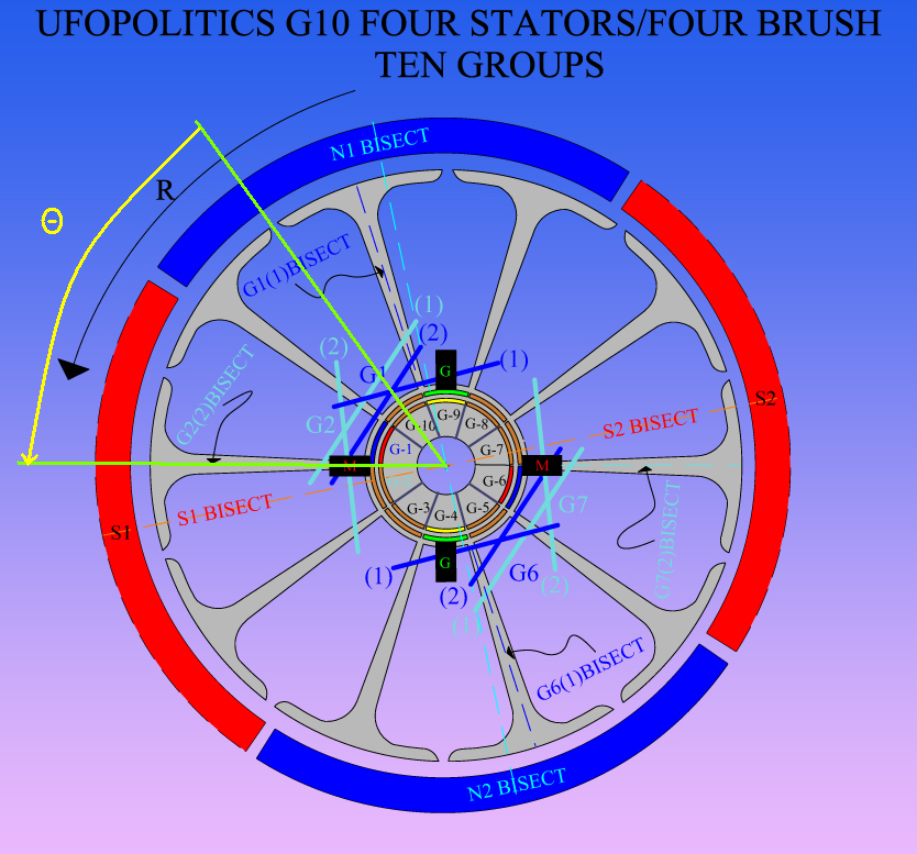
You are asking for a Ten Pole in a Four Stator/Four Brush Housing...and Nope, unfortunately it will not work the same as the P10 Two Stator Rotor, nor the same as in the G-10 Two Stators, in the All North Type...some modification must take place here...take a look below:
[IMG][/IMG]
Even though We are using Two Coils per Group and we could call them "Pairs"...We have the same approach as the RS Five Poles...because of the overlapping between Two Coils.
I tried with Three Coils in each Group...nope can't do it...why?
Because in a Four Stators we are limiting (shortening) the Angles of Interactions between N-S ...never the same as in a Two Stator. Yeah, in the 4S We have Interact Angles of 90º between N-S Stators Bisectors.
Let´s take a look above Diagram...and read below...
G1(Dark Blue) Coil One (1) wraps around Three Poles, so Center Pole center would be its Bisector, and I show it as G1(1)BISECT.
Notice Brush M on left is just starting to make contact according to Rotation "R" with G1 (Blue) Commutator Element...good so far?...great.
Now, like I have said before in ALL North Groups, We MUST LOOK at the "Leaving Group" for a perfect alignment, in this case it is G2 in Light Blue...So then in that Group We must specifically look at the LAST COIL BISECTOR G2(2)BISECT... AND...MAKING SURE it is not Aligned/Nor Passed South Stator Bisector (S1).
And in real builds, we must make sure when it's still in contact with brush (meaning being energized) it still do not aligns with South Stator Bisector...until it is completely disconnected.
So, what I always do here...is to Fire the coming Coils (G1) First Coil (1) Bisector...AS CLOSE AS POSSIBLE TO North Stator Bisector (Repulse Stage)..leaving Us a good space at G2 (2) Bisector which is at Attract mode.
The same exact deal takes place at 180º with G6-G7...
The same way I have recommended before...doing G1-G2, then doing G6-G7...and so on, in order to balance Copper at 180º.
Any doubts let me know...
Regards
Ufopolitics
To understand the firing sequences in your diagrams, I started drawing lines between the energizing motor brush set and the centerline of the matching coil set. I was trying to apply the nearest unipolar design of a quad stator, your last bosch rendering. It has the equivalent "2.5 poles angular measurement" for this definition. Translating to a 10-pole rotore would be 1.25 poles.
Very helpful how you make clear the changes in geometry for a 10-pole changes everything. I have showed your diagram re-interpreted with my theta timing angle. To me this is the definitive parameter in wiring your diagrams and helps me see things better. So here it is if it helps anyone else.
Theta angle subtended by green angle
While I tried to reverse engineer the 20-pole bosch diagram erroneously, you show the angle to be 1.5 poles and a simple 2 subcoil group is necessary!
Thank you very much!
PS almost complete Monster driver board 2 which will make available a PWM system for my 2-stators!!! See other thread.
Hi UFO and all, just a quick update with where I am up to.
Have just finished planting the years Garlic crop, the rows are 100mt long and I have planted 28 rows this season, enclosed pic's.
All the rows are heavily mulched with material harvested, on farm, with my forage harvester, and placed by hand, the seed is also hand planted.
We are in drought here, luckily I have an endless water supply from an underground bore, and can run a small irrigator 24/7 if needed.
Only trouble is the energy cost to run it,( about $30.00 / night AUD.)
Have just planted yesterday my Wheat crop, on the back of 8mm or rain, it's very late, almost outside the planting window, so fingers crossed.
Now it's just a matter of a bit of catch up work and hopefully I will have some time to wind my all north MAG3 rotor.
I am waiting for two rotor sets at present and have talked to several others that are also. At least now we know how long to wait as before we got not answer when we asked Dyann how long it would be.
Leave a comment: