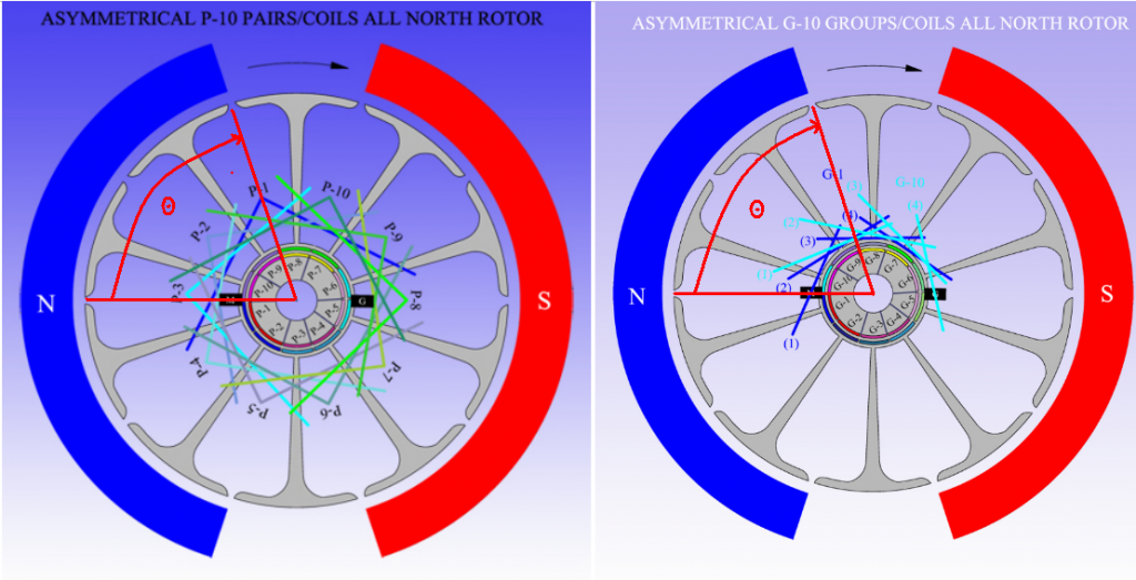
About Imperial All North Rotor Only...
Hello Guys,
I have been talking to Dyann Derosa at Imperial Electric about putting up together for all of Us here a special price on JUST A ROTOR KIT for the P56 Imperial, which is EXACTLY One(1) Rotor with Shaft On, and Two (2) Commutators...That was about a few days ago, and I just got the email from her...
Rotor w/Shaft (Part# 0510052): 35.00 USD each
Commutators (Part# 0567028C):24.00 USD each X2=48.00
ROTOR KIT: 83.00 USD
Those are great news!!...but, the bad news is that there is a delay of Six Weeks (she said maybe sooner)...because of Commutators Supply.
I thought for all of Us, owners of an Imperial already put together, Housing, mainly with Brush Caps aligned, Magnets etc,etc...it would be a great deal to own one of this Rotor Kits...since we could exchange in the same Housing to run different tests with different windings...basically comparing N-S Pairs versus N-N Pairs and All North Groups...
Regards to All
Ufopolitics
Announcement
Collapse
No announcement yet.
My Asymmetric Electrodynamic Machines
Collapse
X
-
G10_Quad Stators
Originally posted by sampojo View PostHere is the post when I last brought it up.
So of I do the math myself here, the timing angle you used on your bosch 20-pole is 2.5 poles or 45 deg.
If it is right to use the same angle for the 10 pole that would be about 1.25 poles in an angular measurement.
Ufo, Is this right?
Then just use the same unipolar winding diagram as the dual stator 10-pole?
thanks,
Joe recovering from hip surgery, or where did that horse come from that kicked me in the hip? Almost better now...
Hope You get back to absolutely normal recuperation very soon...
Ok, kind of hard to see what exactly you mean by Theta Angle...normally, whenever we use angles in the All North Types, they are either from Bisector to Bisector or the angle enclosed by the whole Group-Pair...or enclosed by each Coil.
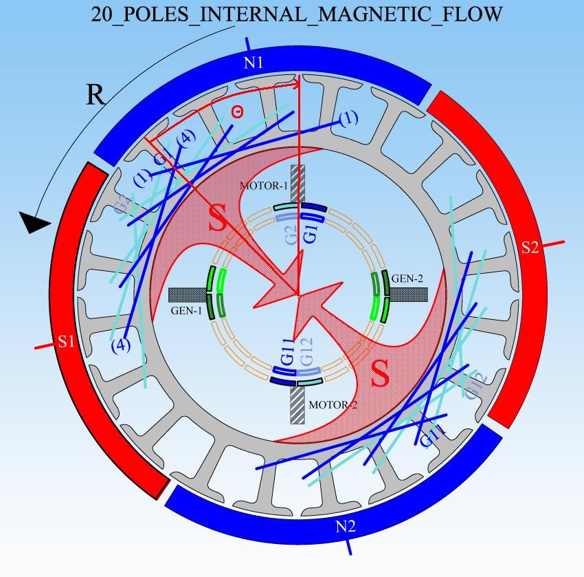
You are asking for a Ten Pole in a Four Stator/Four Brush Housing...and Nope, unfortunately it will not work the same as the P10 Two Stator Rotor, nor the same as in the G-10 Two Stators, in the All North Type...some modification must take place here...take a look below:
[IMG][/IMG]
Even though We are using Two Coils per Group and we could call them "Pairs"...We have the same approach as the RS Five Poles...because of the overlapping between Two Coils.
I tried with Three Coils in each Group...nope can't do it...why?
Because in a Four Stators we are limiting (shortening) the Angles of Interactions between N-S ...never the same as in a Two Stator. Yeah, in the 4S We have Interact Angles of 90º between N-S Stators Bisectors.
Let´s take a look above Diagram...and read below...
G1(Dark Blue) Coil One (1) wraps around Three Poles, so Center Pole center would be its Bisector, and I show it as G1(1)BISECT.
Notice Brush M on left is just starting to make contact according to Rotation "R" with G1 (Blue) Commutator Element...good so far?...great.
Now, like I have said before in ALL North Groups, We MUST LOOK at the "Leaving Group" for a perfect alignment, in this case it is G2 in Light Blue...So then in that Group We must specifically look at the LAST COIL BISECTOR G2(2)BISECT... AND...MAKING SURE it is not Aligned/Nor Passed South Stator Bisector (S1).
And in real builds, we must make sure when it's still in contact with brush (meaning being energized) it still do not aligns with South Stator Bisector...until it is completely disconnected.
So, what I always do here...is to Fire the coming Coils (G1) First Coil (1) Bisector...AS CLOSE AS POSSIBLE TO North Stator Bisector (Repulse Stage)..leaving Us a good space at G2 (2) Bisector which is at Attract mode.
The same exact deal takes place at 180º with G6-G7...
The same way I have recommended before...doing G1-G2, then doing G6-G7...and so on, in order to balance Copper at 180º.
Any doubts let me know...
Regards
UfopoliticsLast edited by Ufopolitics; 07-22-2014, 02:40 PM.
Leave a comment:
-
UFO, looking at building an new rotor for quad stator GM window motor
Here is the post when I last brought it up.
Originally posted by sampojo Post #6586 View PostHi Ufo
I am thinking about making a new rotor. I like my QP10 quad motor for power generation capability, since the motor body is wall-to-wall covered with magnets in a quad stator layout. It has a construction weakness in that I used solder on the external wiring connection, that I believe I can replace with crimps. At 26ga it ran a little hot at 130defF coming out along the endplates., .6-.7ohm coil pair wQP10 winding pattern.
I like my doublerotor dual stator alot since it ran cooler, twice the wire then of course and ohms prbly at about 1.1 per group, apparently less powerful too!. I don't like the shorter magnets now either.
You asked me a question back on pg 219 P6566, here is the discussion:
When you asked if I could put the G10 rotor in the body of my QP10 you seemed to imply that the dual stator group winding might work in the Qaud stator design. Maybe not huh? But what about the P10 unipolar which I would like to investigate. Sure I can do the P10 double rotor for a dual stator and we know it should work well, but I like the wall-to-wall magnets in the QP10 motor body. I guess 26ga is still optimum there, since I should be able to recoup heating as a problem by using pulsers, which I am starting a more agressive assembly campaign on those. But I think you have alluded to differences in quad stator designs. And overall I want to test the Pairs unipolar design. I think the 44000 rpms you got on the RS 5-poles unipolar pair design is the effect I want to work with most.
Question: Do I need a redesign of the P10 unipolar dual stator design for a Quad Stator motor?
Looks like answer is no if I compare the timing angles, group vs pair unipolar looks constant. But the 20 Pole Quad stator Bosch diagram timing angle looks a little larger at 4 1/2 poles vs. a translated 4 poles (Theta in the diagrams)
10-pole Group vs Pair design have same theta
Looking at coil G1 firing here, 20 pole quad stator has similar Theta, maybe a little smaller by 1 1/2 pole arc?
So It looks like rotors would not be interchangeable in unipolar motors between quad and dual stator designs to me since the theta's are very different, and one leading and one lagging the motor brush.
So a Pair unipolar 10-pole design for a quad stator would use the same timing angle used by the Quad stator 20-Pole apparently, and the sub-coils would subtend 2-poles?
Thanks, Ufo
If it is right to use the same angle for the 10 pole that would be about 1.25 poles in an angular measurement.
Ufo, Is this right?
Then just use the same unipolar winding diagram as the dual stator 10-pole?
thanks,
Joe recovering from hip surgery, or where did that horse come from that kicked me in the hip? Almost better now...
Leave a comment:
-
Originally posted by DadHav View PostWELL, let me be the first to congratulate myself! Ha, thats the first time I used one of those little things here. You know I'm just kidding UFO. I appreciate your candor very much and feel good that we actually had a meaningful conversation. All here are inventors and all should feel obligated to search for avenues that lead in the right direction. If something seems to be off course it should be talked about right? A lot of time and sometimes embarrassment can be saved by catching things before they go to far. It was a pleasure to be some help. I feel so good I might do a practice confetti drop on my simulator.
I have a good friend in Portugal named Eduardo. Ed just told me something very nice regarding some personal setbacks of my own and I loved the quote:
"You certainly can't control the direction of the wind, but you can adjust and trim your sails" I hope soon you guys will make the right adjustments and have some smooth sailing.
Kindest Regards
John H.
for your input and showing how to critique someone's work properly
Well gentlemen, let the fun begin with the 4 stators!
Keep it Clean and Green
MidazLast edited by Midaztouch; 07-23-2014, 12:48 AM.
Leave a comment:
-
Originally posted by Ufopolitics View PostHello John,Hello to All,
Basically this post is an apology on my end...I was dead wrong, and I am admitting it here...
@DadHav: I did exactly the same Test You did, John...with my own set up, except there was no Motor hooked, and You are COMPLETELY RIGHT, Supercaps get a charge when I set them on Parallel, then the whole thing repeats as well as it did with Motor connected in Series all Caps...it shows OVERUNITY, BUT IN MUCH LESS TIME that it took with Motor on...
Sorry for being so stubborn!...but at the same time, Many Thanks for doing that test for Us.
We learn from our mistakes...it is part of Experimenting over and over...as it is the great deal of Open Sourcing our research out here.
The Circuit, even as independent Banks 1 & 2 on this Connection, still have Parallel connection between their Batteries and Caps on each side...
So let's call this whole Video and Test as VOID, NULL...not good and a tendency to give WRONG READINGS from Motor.
When We move into the All North Groups and Four Gate Machines, then We will repeat same Test, but this time Batteries and Supercaps would be in completely isolated circuits from each others...so the conclusions, either great or terribly bad...still will get Us to think if or not we are on the right track
Thanks again John!
I will come back soon and please, I know has been quite long, so make sure the Confetti keeps being fluffy...
Regards to All
Ufopolitics
I have a good friend in Portugal named Eduardo. Ed just told me something very nice regarding some personal setbacks of my own and I loved the quote:
"You certainly can't control the direction of the wind, but you can adjust and trim your sails" I hope soon you guys will make the right adjustments and have some smooth sailing.
Kindest Regards
John H.
Leave a comment:
-
My Apologies
Originally posted by DadHav View PostWith a smile on my face: UFO, you and I are probably the most diametrically opposed people on the face of earth when it comes to thought processes and the way things should be tested. That will always get in between us. That doesn't mean I have any dislikes towards you or disbelieve in your cause. I may have beat around the bush to much about the whole topic I was invited into. I just plain disagree with the flash test as you call it as it would pertain to the claim of over unity. I just tried to show a flash comparison using a battery and capacitors. My test results, as you had in your final measurements, where very similar. I would certainly imagine if I used one of my stator motors with generator coils I could have made a very impressive similar video but that's all there is to it, you and I and everyone else knows all these conversations can be flushed right down the drain when a real life, real user friendly practical application is demonstrated. I hope Kogs drives across the continent puts a propellor on Nesse and runs up on the Florida cost line to say hello. I mean it Kogs, Dana, Richie and everyone else. I would like to see this work, so don't get me wrong on that. I've just been adverse to testing techniques and quick claims from the beginning. That makes me so different that I need to keep my distance and come around only once in a while to disrupt things. LOL.
John
PS Have to go now and make sure the confetti in the plane isn't sticking together. It will need to be nice and fluffy for the celebration flight.
Basically this post is an apology on my end...I was dead wrong, and I am admitting it here...
@DadHav: I did exactly the same Test You did, John...with my own set up, except there was no Motor hooked, and You are COMPLETELY RIGHT, Supercaps get a charge when I set them on Parallel, then the whole thing repeats as well as it did with Motor connected in Series all Caps...it shows OVERUNITY, BUT IN MUCH LESS TIME that it took with Motor on...
Sorry for being so stubborn!...but at the same time, Many Thanks for doing that test for Us.
We learn from our mistakes...it is part of Experimenting over and over...as it is the great deal of Open Sourcing our research out here.
The Circuit, even as independent Banks 1 & 2 on this Connection, still have Parallel connection between their Batteries and Caps on each side...
So let's call this whole Video and Test as VOID, NULL...not good and a tendency to give WRONG READINGS from Motor.
When We move into the All North Groups and Four Gate Machines, then We will repeat same Test, but this time Batteries and Supercaps would be in completely isolated circuits from each others...so the conclusions, either great or terribly bad...still will get Us to think if or not we are on the right track
Thanks again John!
I will come back soon and please, I know has been quite long, so make sure the Confetti keeps being fluffy...
Regards to All
Ufopolitics
Leave a comment:
-
Originally posted by MidaztouchSteve
Your an easy target but I'm deleting all of my post.
My team has work to do!
UFO,
I don't won't Erfender around anymore. Is that ok with you?
Midaz
I'm cool with that....erase your garbage and I will do the same and that will be the end of it.
added...
Since you opened this last post of yours as a threat, I take that as a sign that this isn't over.....I'm prepared....come when you're ready!Last edited by erfinder; 07-21-2014, 11:42 AM.
Leave a comment:
-
MODERATORS on vacation? both of you take your **** back to skype.....UFO hopefully this motor has torque unlike you other assymetric motors... are you going to send this new motor to get tested again? hopefully it works out this time
Leave a comment:
-
Originally posted by Ufopolitics View PostShould I take that as a Compliment?...it depends right?
John, for God Sake, let's try to use some common sense here...and keep a Logical Dialectic Conversation.
What I mean(t) is/was that all I did in that Test...was to STOP, PAUSE the Generator and Motor Action, in order to check the obtained Energy Read Out at the Capacitors Banks, knowing what Charge they had from previous reading. Then also check Batteries Lost or Gained Power...then compare results...that was all the Test was about.
It is clearly understood that if I turned OFF Generator...no more Energy would be sent to capacitors, nor batteries...and they will drain out...same way batteries also will drain by hooking a load bulb like I did...but that is not the point of this simple test.
The same way it is NOT the Point to observe which one will drain faster?...Batteries or Caps?...NOT the Point either.
All I did was a "FLASH READ OUT"...where I "PAUSED" the System from running in order to conduct a reading.
More simple than that...I believe it is not possible.
John, You have been away from this Thread for a while now...I don't know if you have been looking at it from an outsider end either...but, based on your comments about my Machines draining High Amperage...Those are "Past News" John...and I remember you did reply here when I was disclosing my New All North Winding Type...and I loaded my Comparison Video Against my own previous creation...the North-South Pairs Type on this VIDEO...
You will be surprised what amount of Amperage this Machine draws when running in this kind of set up...but it is completely fine, I can run, anytime, a short video, where I show you and all here...what the little motor drains as Amperage.
Now, you mentioned "Mechanical Loading"...and I colored it red above...and that is Out of Context here...I am NOT considering Mechanical Output...so why should I want to add a mechanical load to machine at this point with this specific test?
We are just comparing here, Electrical IN versus Electrical OUT...just like Two Attached Machines would do, where One is the Prime Mover, and the other one is the Generator Head...except here, we have them both within the same Housing...but it is the same exact concept...so, is that a problem with you?
Perfect Analogy!...And that is exactly what took place...5 Watts Generated versus 2.24 Watts Input.
Wouldn't the Difference (Subtraction) from the First Read Out from Main Source (Batteries)...and after, Minus End Read Out after run... wouldn't this difference give Us the Lost, Consumed Total Energy by Machine, John?
Or...should We let Batteries rest more time?...then re-test them again with load?...because you know, and I know...as many know here... that would be completely favorable to my testing/machine results.
Well, it is absolutely understood, that if I disconnect the Generating Source to Banks...meaning, the Machine and all its Circuitry...there would not be any more power added to the Banks...The Capacitor Banks will not "Self Recharge"...so I do not understand your point here?
My Test -again- was a Flash Test...where I Paused/Stopped the whole System from producing more Energy in order to conduct a -so far, up to that point in time- accumulation of power on both Banks reading.
On a Vehicle We have a Battery and an Alternator attached to Voltage Regulator and Diodes Bridge Circuitry...in order to maintain Battery Charged...Now, We could disconnect the Charging Circuits by turning Off Alternator...and Vehicle would keep running...but, for how long?...a few miles before it comes to a complete stop?
Then We would need to re-charge Battery using an External Source...since Starter Motor would not even spin...the Self Charging System -built in- would not operate unless We turn on the ICE Engine again...
Same approach applies here. We turned Off and disconnect the Engine that kept those Capacitor Banks Charged...so adding a load to them was just to check Energy gained on 11+ minutes of charge.
But the comparison of examples is wrong John...You do are just Transferring Power from one store reservoir to the other through plain connections...you do not have an Electrodynamic Machine achieving a Mechanical work...or speed and torque, as a Buffer, while doing that...You are not Pulsing, nor swapping Coils within a Magnetic Field...besides the Bulb you used is obviously not the same type I used on my test...you noticed the amps it drew from both banks, compared to what you are writing above...so that means it will run the system faster.
On the above Experiment is just another "Flash Reading", similar to mine...except, that if you keep doing the same experiment over time...charging discharging Caps and testing Bulb again and again...batteries will end up running out of Energy at some point it could not recharge Caps anymore...just because there is no Generation of Power by a Rotating Machine there...like I have shown.
Eventually that is exactly my Goal, as of many here on this Thread.
When We move on, to Four Gates Systems, We would be able to Install separate Meters (V & A) at Input and Output Banks, since they would be completely Independent from each others (just dependent on Space and Time)...then, We all could do more accurate test and comparisons than the one I have shown with a machine that has just Two Gates, where everything is mixed up, Input and Output...and there is no way to have separate readings from Batteries and Super Caps while Machine is spinning ...which is absolutely the Ideal scenario.
Ufopolitics
John
PS Have to go now and make sure the confetti in the plane isn't sticking together. It will need to be nice and fluffy for the celebration flight.Last edited by DadHav; 07-20-2014, 06:39 PM.
Leave a comment:
-
Constructive dialogue
I can appreciate the dialogue between Dadhav and UFO.
Others why can't you get your acts together and have some descent dialog! Look at Dadhav. He came, drop his opinion, vid and ideas. UFO answered back with in the realm of HIS testing and future outlooks.. They may not be on the same page, but they are having intelligent conversation like adults.
Thank you Gentlemen
MidazLast edited by Midaztouch; 07-21-2014, 11:39 AM.
Leave a comment:
-
Dizzy but Enjoying the Show!
Originally posted by Cornboy 555 View PostVery well spoken DANA, and MIDAS, Thanks, you guys rock.
UFO, can you please be just 2 steps ahead instead of three, you're making me dizzy.
Warmest regards everyone, Cornboy.
I know you can not get any Australian TV Shows with this rating and such content full of excitement!!...
Just finish putting together your MAG 3...and contribute to make this Show even greater Controversy with your Reading results.
Realize that if Imperial could run on One Motor Gate and Three as Generator...
In Your ALL NORTH, MAG 3 you could afford Two Gates as Motor, apart by 180º... and Four Gates (yes 4 @ 60º apart) dedicated to fill Capacitor-Hybrid Lipo's Banks...
What a Machine that would be my Friend!!
Regards
UfopoliticsLast edited by Ufopolitics; 07-20-2014, 04:03 PM.
Leave a comment:
-
Originally posted by DadHav View PostI know by now UFO you are a very clever man with words.
OU for a minute or a few seconds is not a viable question because saying you have it for a second is an admission that means absolutely nothing because you can draw as much current as you want for seconds.
What I mean(t) is/was that all I did in that Test...was to STOP, PAUSE the Generator and Motor Action, in order to check the obtained Energy Read Out at the Capacitors Banks, knowing what Charge they had from previous reading. Then also check Batteries Lost or Gained Power...then compare results...that was all the Test was about.
It is clearly understood that if I turned OFF Generator...no more Energy would be sent to capacitors, nor batteries...and they will drain out...same way batteries also will drain by hooking a load bulb like I did...but that is not the point of this simple test.
The same way it is NOT the Point to observe which one will drain faster?...Batteries or Caps?...NOT the Point either.
All I did was a "FLASH READ OUT"...where I "PAUSED" the System from running in order to conduct a reading.
More simple than that...I believe it is not possible.
I'm sorry to say as much as I want to see over unity I do not from your video. I did see some of your earlier drawings and videos but I was waiting for something a little more gathered up like this one. You don't like to complicate things, you say, but I think people will see what I do. You have a machine that uses an unspecified amount of wattage to charge an energy bank whether that be a capacitor battery or anything else no matter what the connections are. You have a motor running that could mean something but not likely if the current draw goes way up with mechanical loading. Still yet untested. In it's most basic form you used some amount of energy in one place and stored it in another. If you have over 200 percent over unity that means to me that you have stored twice the amount of energy in a reserve place than what it took to get it there. Is this a wrong analogy?
You will be surprised what amount of Amperage this Machine draws when running in this kind of set up...but it is completely fine, I can run, anytime, a short video, where I show you and all here...what the little motor drains as Amperage.
Now, you mentioned "Mechanical Loading"...and I colored it red above...and that is Out of Context here...I am NOT considering Mechanical Output...so why should I want to add a mechanical load to machine at this point with this specific test?
We are just comparing here, Electrical IN versus Electrical OUT...just like Two Attached Machines would do, where One is the Prime Mover, and the other one is the Generator Head...except here, we have them both within the same Housing...but it is the same exact concept...so, is that a problem with you?
If you have over 200 percent over unity that means to me that you have stored twice the amount of energy in a reserve place than what it took to get it there. Is this a wrong analogy?
If you knew the amount of energy it took to run the motor for the experiment then you should be able to run the motor for twice that amount using what you stored in the capacitors or at least a load that can use the reserve bank to depletion no? You have not showed anything close to that scenario.
Or...should We let Batteries rest more time?...then re-test them again with load?...because you know, and I know...as many know here... that would be completely favorable to my testing/machine results.
Your test is more like measuring a higher voltage over a generator coil that is in series with the motor coil. Measuring a higher voltage on the output Whether it be in operation or stored doesn't mean OU. In this case you briefly added an amp reading for the convenience of figuring wattage which can be impressive but means nothing if it can not be sustained long enough to estimate the total amount of energy you have available in the cap bank.
My Test -again- was a Flash Test...where I Paused/Stopped the whole System from producing more Energy in order to conduct a -so far, up to that point in time- accumulation of power on both Banks reading.
On a Vehicle We have a Battery and an Alternator attached to Voltage Regulator and Diodes Bridge Circuitry...in order to maintain Battery Charged...Now, We could disconnect the Charging Circuits by turning Off Alternator...and Vehicle would keep running...but, for how long?...a few miles before it comes to a complete stop?
Then We would need to re-charge Battery using an External Source...since Starter Motor would not even spin...the Self Charging System -built in- would not operate unless We turn on the ICE Engine again...
Same approach applies here. We turned Off and disconnect the Engine that kept those Capacitor Banks Charged...so adding a load to them was just to check Energy gained on 11+ minutes of charge.
Of course this is my opinion and you asked for it. I could be wrong and will admit to it when I see a test that is convincing to me. Let me tell you about a test I just did. I took two AA low self discharge batteries off the shelf and checked the voltage. Their resting voltage in series was 2.616 v. I took two 270 farad hybrid super caps and carefully discharged them to 0 volts. OK you and I know they will recover slightly almost no matter what you do but I put them parallel on my proto board and connected the battery pack directly to them. It took about 15 minutes for the caps to come to about 2.3 volts. I let the caps and batteries set for short time then lit a small 12 volt bulb like you see in my experiments. The battery pack which was at 2.588 volts and still rising showed very little decrease in voltage (millivolts) after charging the caps then sitting for a short time. With the bulb connected to the pack my voltage dropped to 2.576 volts and bulb was using .015 amps. (.0386 watts) I then connected the capacitors in series and connected the 12 volt bulb. The bulb was noticeably brighter than what it was on the batteries. The voltage on the cap bank was 4.394 volts and the current draw was .021 amps. (.092 watts) Ok .092 divided by .0386 equals 2.383 or over 200 percent efficient. Ok now I ask you, did I prove overunity tonight whether it be for a second, minute or hour? I think not.
On the above Experiment is just another "Flash Reading", similar to mine...except, that if you keep doing the same experiment over time...charging discharging Caps and testing Bulb again and again...batteries will end up running out of Energy at some point it could not recharge Caps anymore...just because there is no Generation of Power by a Rotating Machine there...like I have shown.
I always wait for the day when someone will take an unmodified motor and compare it to a modification in a way that even the most uneducated person can understand. I don't care if it's a model or a scooter or car but how about one beside the other and which one will go further down the road. Not a meter of calculation even needed.
I think I might be getting in trouble again but best regards.
John
When We move on, to Four Gates Systems, We would be able to Install separate Meters (V & A) at Input and Output Banks, since they would be completely Independent from each others (just dependent on Space and Time)...then, We all could do more accurate test and comparisons than the one I have shown with a machine that has just Two Gates, where everything is mixed up, Input and Output...and there is no way to have separate readings from Batteries and Super Caps while Machine is spinning ...which is absolutely the Ideal scenario.
Ufopolitics
Leave a comment:
-
Originally posted by Midaztouch View PostA1 Mo-Gen can:
1.) light lights
2.) store energy in capacitor banks
3.) have a mechanical load
At The Same Time!
At The Same Time!
At The Same Time!
This is what we are saying here. Now, you tell me what other system can give you this type of freedom of performance!? This is the real question that you must ask yourself.
Dadhav, what motor can you find that has these 3 attributes listed above?
You know that the A1 Mo-Gen will fly your RC Plane with lights in the dark. You can tap into the capacitor bank reservoirs to power servos that will give you retractable landing gear and doors that open and close for the confetti drop. Filming the whole celebration from the comforts of you living room while feeding your cute dog treats on your lap!lol
When we get into the four stators and above we will enhance the big 3 listed above...at the same time! It's light weight and no need for any cooling system! This is the real deal, the truth! Don't worry about the amps, the 4 stators and above will more than make up the difference. This is military grade technology! Lockheed Martin, Boeing, UAL, Pratt & Whitney, Space X, Mercedes, Honda etc.. all those big names have nothing on this technology... NOTHING!
You guys are so hung up on Over Unity, OU. You forgot about the most important thing, Overall System Performance, OSP!
It's clear for everyone to see. Let's work together and push this technology to the limits!
Keep it Clean and Green
Midaz
Take carr.
John
Leave a comment:
-
Originally posted by prochiroYou guys are not understanding a simple question and adding in something that is not part of that question has nothing to do with the intent of this experiment.
Creating more power than is needed to run a motor is what this is about. Using that energy to make that motor run as a self runner is not what this experiment is about. One glass of water becomes five glasses of water at end of test is all he asked you about. We have five glasses of water at the end and actually thru away another glass full that we aren't counting. Why can not you guys just say, there does seem to be four more glasses full than when you started. Our work is not complete with this test and in fact with this small motor set up the way it is, having those readouts is a great step forward for us. There is only one generator with this setup and you both know full well that we have motors to be tested with three generators. That is one of our next goals.
Let me ask you a question...
Have you made a system that can show volts and amp (WATT's) grow like this and be held in a container for future use?
Dana
Have you made a system that can show volts and amp (WATT's) grow like this and be held in a container for future use?
Dana[/QUOTE]
Dana this is a hard question for me to figure out. Haven't we all done similar any time we charged a capacitor using a pulse circuit? I have to say I have many videos on my channel showing almost unbelievable capacitor charging from simple circuits. How about cap dump circuits that all charge caps above input voltage before being used to recharge a battery. If you measured any of these caps the way the test was in the video they would likely show an over unity situation also, but did you ever have provable over unity with one of them. I never did.
Did I ever grow watts? No but I saved them which is something I haven't seen here. I posted a video at the beginning of the thread somewhere and it never had a comment that I know of. In the video I have a parallel coil motor with the generator coil connected to a full wave rectifier. I use a 12 volt battery and 12 volt bulbs in the experiment. When I add the bulb to the output coil the current draw of the input almost drops in half with the motor not changing speed. Now I ask you or anyone else here what happens when you add a load to your generator coil on any of the motors demonstrated here? Does the motor stay the same speed while the current draw goes down. If not then maybe I really don't have sh t for brains like others have said here. LOL
Just a reminder:
https://www.youtube.com/watch?v=0JmkuQliVWo
John
PS an edit here. I think I saw a comment that said something like it is impossible to connect the output back to the input at the time the motor is running or something like that. Well notice that's exactly what I do at one point in the video and when I make the connection the motor stays the same speed but the current drops nearly in half. I know this has nothing to do with what your doing here. Or does it. I offered it up but no one was interested in where or not there were any similarities.Last edited by DadHav; 07-20-2014, 02:01 PM.
Leave a comment:
Leave a comment: