Announcement

Collapse
No announcement yet.

My Asymmetric Electrodynamic Machines

Collapse
X
 
  • Filter
  • Time
  • Show
Clear All
new posts

  • Amp Draw

    Originally posted by Turion
    UFO,
    Do you have any idea how many amps this motor should draw? It measures right at one ohm per coil and 16 coils. I ordered two 65 amp meters, because the amp draw I am seeing is way over 10 amps, and that's as high as my meters go, and my analogue gauges only go up to 5 amps. I can't do the dyno test without a meter that will measure the amp draw correctly.

    I'm trying man! Seems like every time I try there is some major setback. It will be a few days before those meters come in. In the meantime, I will be FORCED to play with this motor on the 3BGS.

    I posted the current schematic on the 3BGS thread.

    Dave
    Hello Dave,

    Let me ask a silly question...Are you applying an Electrical load to Machine Output when running the Dyno test?...I mean, as simple as some CFL's, let's say five of 23 watts connected in parallel?
    I strongly believe that would help to lower the Machine running Amps inside armature coils...

    My Machines if you do not provide an "Output Gate Relief"...the currents will keep bouncing back at your Input...and as more mechanical load you apply to the shaft when making the Dyno Testing (which lowers RPM considerably)...the Higher the currents you will get there my dear friend...and they have to go "somewhere"...so they are kicking back at your Input Meter...

    Now, I do not believe that is a real Amp draw from battery...let me ask you something...Do you have a Battery Load Tester?...the ones that come with a huge resistor inside...NAPA have them...if you do, make a reading before and after Dyno Test on Battery...to see if it lost any Amperage under Motor load...

    In the meantime, I will be FORCED to play with this motor on the 3BGS.
    Oh!...And You are sooo "upset" to keep playing with your three batteries!!...
    Yeah right!

    Thanks I got the schematics.

    Regards


    Ufopolitics
    Last edited by Ufopolitics; 08-16-2012, 10:44 PM.
    Principles for the Development of a Complete Mind: Study the science of art. Study the art of science. Develop your senses- especially learn how to see. Realize that everything connects to everything else.― Leonardo da Vinci

    Comment


    • There are still abusive, offensive, lewd and sexually deviant posts to be removed. If they
      are not removed I will begin requesting in this thread on a regular basis that
      they be removed. I have already asked several times. I found this one and
      looked no more, there may be others.

      I can be abusive as well if I want to, so lets be fair with each other please.

      http://www.energeticforum.com/202260-post23.html

      prochiro
      Senior Member

      Join Date: Jun 2011
      Posts: 113
      Farmhand, you piece of ****
      You are a dog and need to be confined to your dog house with a big chain. Stop causing trouble in other threads. Maybe you could find a chicken to screw, AGAIN.
      No Regards

      Comment


      • @Prochiro (Dana)

        This Post is STRICTLY DIRECTED TO MEMBER PROCHIRO,

        Hello Prochiro,

        Will you please remove that post cited above?

        Please, it will save Us some Noise from getting here (Again)

        Regards


        Ufopolitics
        Principles for the Development of a Complete Mind: Study the science of art. Study the art of science. Develop your senses- especially learn how to see. Realize that everything connects to everything else.― Leonardo da Vinci

        Comment


        • Opinions...and answers...

          Farmhand comment on This Thread/ Post#5
          Hi Carroll, As far as motors go I think they are already quite efficient...
          My answer...


          This all tells me there is no free energy in a motor, all that is possible is closer to 100% efficient. Motors are for delivering shaft power and if we reduce maximum input power we reduce maximum shaft power..
          My other answer:


          P.D: I wanted to get more ...but program did not allow me to...They said:

          You have included 33 images in your message. You are limited to using 15 images so please go back and correct the problem and then continue again.

          Images include use of smilies, the vB code [img] tag and HTML <img> tags. The use of these is all subject to them being enabled by the administrator.
          What a shame!!...
          Last edited by Ufopolitics; 08-16-2012, 11:48 PM.
          Principles for the Development of a Complete Mind: Study the science of art. Study the art of science. Develop your senses- especially learn how to see. Realize that everything connects to everything else.― Leonardo da Vinci

          Comment


          • hey ufo,

            Now I understand, your stator is not completely wound all the way, on the bottem it is not connected in center. And it is two poles because field reverses, duh... so of course I could not use a rotor wound for 4 pole.

            Also, I will stop being lazy with my terms. Poles on stators, armatures on rotors.

            I will try the 16 arm rotor wound with the 12 pole(just kidding), the 12 arm pattern.

            Thanks for your patience

            Comment


            • Arms?

              Originally posted by machinealive View Post
              hey ufo,

              Now I understand, your stator is not completely wound all the way, on the bottem it is not connected in center. And it is two poles because field reverses, duh... so of course I could not use a rotor wound for 4 pole.

              Also, I will stop being lazy with my terms. Poles on stators, armatures on rotors.

              I will try the 16 arm rotor wound with the 12 pole(just kidding), the 12 arm pattern.

              Thanks for your patience

              Machinealive,

              Now I understand, your stator is not completely wound all the way, on the bottem it is not connected in center. And it is two poles because field reverses, duh...


              It does not matter if the field reverses, still it has Two Poles(2)...didn't you noticed I was NOT pulsing it but feeding it completely off the battery terminals in the Timeless Machine video, meaning linear?

              Ok, I will try again...

              Stator is a Two Pole anytime, when feeding linear, Two Steady Poles are generated, One North other South...But, when we pulse it...it is still a Two Pole Stator but that keep reversing its Two Poles...according to our frequency ratio.

              Regards


              Arms?...LOL


              Hope is clear now..


              Ufopolitics
              Last edited by Ufopolitics; 08-16-2012, 11:45 PM.
              Principles for the Development of a Complete Mind: Study the science of art. Study the art of science. Develop your senses- especially learn how to see. Realize that everything connects to everything else.― Leonardo da Vinci

              Comment


              • Commutator Setup

                Originally posted by Ufopolitics View Post
                Hey Vince!!

                Great work on the Modified!...Now your winding video is awesome, yes, that is exactly the way to go...So I was reviewing your short post...Resistance is Ok, 30 awg is ok...Until I read...


                Is that Red Quoted (P1M-P1G)...a mistake in your writing here...or you did measure resistance from P1M to P1G?...Meaning you joined Coil Pairs terminals at commutator elements 180 degrees apart?

                Please let me know...

                Now, the other thing I have noticed according to your video...you still have a Plastic Brush Cap on the Modified Core...was that the way you had it when you ran it?...because it is wrong...Brushes are supposed to be rotated 90 degrees...I notice the contact terminals are not rotated but as they come from factory...

                Watch my diagram again...below, note brushes related to stators...and tell me...


                [IMG][/IMG]


                Thanks


                Ufopolitics
                Hey UFO,

                Thanks for the help! I made a short video to explain my commutator setup. I think the commutators are correct. My brushes however are definitely in the wrong orientation. Mine are setup at 12 & 6 o'clock and your instructions are 9 & 3 o'clock. Will this make the motor not work properly?

                You can see the video here Asymmetric DC Motor - Commutator Setup - YouTube

                Thanks again!

                Cheers
                Vince

                Comment


                • Kogs windscreen Motor Mod

                  G'day UFO
                  I today picked up my Windscreen motor/s modified by my local friend Andrew

                  I have some pics here
                  Windscreenmotor_mod pictures by Kogs1 - Photobucket
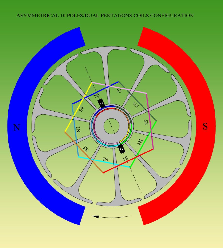
                  You suggested some time ago that the Double pentagon would be Ideal for this motor


                  AS I understand there are 5 pairs of windings that are set parrallel to each other like N1 and S1 being one single winding Just wound similar to the RS 5pole motor instead of a Vee they are parallel.

                  The 2 windings on the original motor were 30.5mtrs each the thickness is 0.7mm diam and measuring 1.84 ohms
                  I did not unwind the wire so I do not know exactly how it was wound

                  As 2 windings
                  Please should I use the same size wire as I think would need to have more length to have the 1 Ohm per pair of coils
                  or
                  Use reduce wire thickness to be able to fit comfortable the wire measuring 1 Ohm

                  I have .8mm wire but I am sure that would not fit so I will have to purchase new wire

                  Kindest regards


                  Ready to wind up

                  Comment


                  • Universal motor: asymmetrical setup

                    Hello UFO,
                    I'm going to try your system with a universal motor: add 2 brush to the 2 existing and use the connections as to your scheme from STATOR_ARMATURE_DIODES_OUT.jpg

                    I also have to change the winding of the rotor according to your specifications ? My motor is 10-poles rotor, 20-hooks commutator

                    I have already converted a 3-poles DC motor with success and I'm making another 7-poles

                    Now my impressions (measured amp and voltage consumption, rpm) with 3 poles motor are:
                    very powerful engine
                    higher consumption respect to the same normal motor
                    possibility of recovering energy
                    if I use a 12 volt battery I have a better charge with a 6-volt battery:
                    using 3 6 volt batteries, 2 for input and one in charge, you can rotate them regularly and optimize the consumption
                    good efficiency in relation to power output but no ou

                    thanks for sharing your experiences

                    ciucianebbia

                    Comment


                    • Kogs Happy Motor

                      G'Day UFO
                      I thought for those that did not see it I I thought Imight show my Happy motor video here

                      UFO's Circuit Running a MY1018 - YouTube

                      Just a bit Extra not shown on the video

                      I also tried driving the modified RS motor or rather ran it with the large Mosfet driver I used in the videos of course it ran with much less power than the MY1018 I did notice that it was not sparking on the commutator until I was pushing it a bit harder then the sparks came and I decided not to push it any further as I am sure it would distroy it
                      When I ran the RS motor with a straight connection with the 12v battery it did not spark or just a bit as the commutator I am sure is not worn in yet.

                      Also Please UFO what do you think about these motors to convert
                      Baldor Australia - Custom Motors

                      Kindest Regards


                      Still working at it

                      Comment


                      • Shunt

                        Originally posted by Turion
                        I am definitely having some problems doing the testing. The amp readings are way too high for any gauge I have the second any load of any kind is put on the motor which the belt DOES.
                        UFO Dyno test - YouTube

                        Dave
                        Hey Dave. I don't know if it would be acceptable or not but I've used a 1 ohm current shunt in the line and then just measured the voltage drop over it. Ohms Law gives you the current easily. Impedance may be an issue but if not, you probably would keep your meter safe. Also scope readings over the shunt will sometimes reveal some interesting things. I was worried about getting a good setup with the friction wheel and never tried it because of that. Someone on the motor building sight mentioned using a motor set up as a generator for a load. The generator shaft would have to be extended into a bearing housing on the back end so the whole generator could be turned. A lever from the motor mount would go over to a scale. When you put a resistive load on the generator the torque would push down on the scale. The length of the lever is used in the calculation. I thought the idea was nice because you could get a lot of information from measuring voltage and current on the generator side as well as have a way to repeat tests at different settings. The issue that stops me from trying it is there may be a hard time getting enough load from the generator to get a near stall condition. Just an idea, maybe someone has tried something similar.
                        John H.

                        Comment


                        • Welcome...

                          Originally posted by ciucianebbia View Post
                          Hello UFO,
                          I'm going to try your system with a universal motor: add 2 brush to the 2 existing and use the connections as to your scheme from STATOR_ARMATURE_DIODES_OUT.jpg

                          I also have to change the winding of the rotor according to your specifications ? My motor is 10-poles rotor, 20-hooks commutator

                          I have already converted a 3-poles DC motor with success and I'm making another 7-poles

                          Now my impressions (measured amp and voltage consumption, rpm) with 3 poles motor are:
                          very powerful engine
                          higher consumption respect to the same normal motor
                          possibility of recovering energy
                          if I use a 12 volt battery I have a better charge with a 6-volt battery:
                          using 3 6 volt batteries, 2 for input and one in charge, you can rotate them regularly and optimize the consumption
                          good efficiency in relation to power output but no ou

                          thanks for sharing your experiences

                          ciucianebbia

                          Hello Ciucianebbia,

                          Ok, let's see...

                          I have already converted a 3-poles DC motor with success and I'm making another 7-poles

                          Now my impressions (measured amp and voltage consumption, rpm) with 3 poles motor are:
                          very powerful engine
                          higher consumption respect to the same normal motor
                          possibility of recovering energy
                          if I use a 12 volt battery I have a better charge with a 6-volt battery:
                          using 3 6 volt batteries, 2 for input and one in charge, you can rotate them regularly and optimize the consumption
                          good efficiency in relation to power output but no ou
                          I see you have already done some modifications on my previous work rendered here, the 3 Pole DC, and you are making a 7 Pole now...

                          It would have been nice, that You would have shared those experiences as all other here have done so far, by exposing your pictures, your videos, as means to show and expose here your true testing and readings, as proof of the veracity of your words.

                          When I first entered here...I was asked for videos, for pictures...for proof that backed up ALL my claims...and I did, and then some more...
                          That is the way so far- as I understand- is "supposed" to be done in this whole Forum right?...not just "baldly" coming here and in a few words-short paragraph...describe the "whole thing" and then "render" an opinion...threw in the "air"..."But Not OU"...and We all -poor innocent and naive creatures- have to believe you?

                          What tests have you done -please explain in detail- to come here and tell me "NOT OU"?
                          Have you read MY WHOLE THREAD?
                          I honestly do not think so...when you are asking...

                          I also have to change the winding of the rotor according to your specifications ?
                          That denotes you have no idea what we are doing here...sorry to tell you this...but the truth is the truth no matter what.


                          I particularly DO NOT like your approach, sorry, it is my point of viewing "things"...and my decision, this is my Thread.


                          Thanks for your interest on my Work


                          Goodbye


                          Ufopolitics
                          Last edited by Ufopolitics; 08-17-2012, 07:33 PM.
                          Principles for the Development of a Complete Mind: Study the science of art. Study the art of science. Develop your senses- especially learn how to see. Realize that everything connects to everything else.― Leonardo da Vinci

                          Comment


                          • Brushes set up.

                            Originally posted by Vincevl View Post
                            Hey UFO,

                            Thanks for the help! I made a short video to explain my commutator setup. I think the commutators are correct. My brushes however are definitely in the wrong orientation. Mine are setup at 12 & 6 o'clock and your instructions are 9 & 3 o'clock. Will this make the motor not work properly?

                            You can see the video here Asymmetric DC Motor - Commutator Setup - YouTube

                            Thanks again!

                            Cheers
                            Vince

                            Hello Dear Vince,

                            Yes Dear, definitively the brushes in a different position other that the one rendered in my Diagram, will not work the same. That is your Main Problem.

                            I watched your video, your Armature winding -like I wrote prior- looks great, however, you just have a misconception when it comes to Brushes contacts names...The lower commutator contact is NOT a generator contact, but the lower Input contact...See, if You apply Input Positive -let's say- to the upper contact (where you are reading resistance)...then the lower contact is where you are supposed to apply Negative from Input...

                            Now, the other tricky thing in this R/S Motors is that Input-Output when looking outside the motor casing...they render in a Diagonal pattern...not straight linear, just because the way brushes brackets are set.

                            Kind regards


                            Ufopolitics
                            Principles for the Development of a Complete Mind: Study the science of art. Study the art of science. Develop your senses- especially learn how to see. Realize that everything connects to everything else.― Leonardo da Vinci

                            Comment


                            • Originally posted by Turion
                              DadHav,

                              That sounds like a lot more precise way to measure the torque of a motor. Is there some place I could read a little bit more about how to set one up? I have several motors with shafts out both ends I could use as generators and lots of sets of bearings that would fit those shafts, I would build a PERMANENT arrangement that I could test motors with in the future.

                              The silly part about this is that putting a double nut on the end of the motor shaft and then putting a torque wrench on the nut does EXACTLY the same thing, and the length of the torque wrench has already been figured into the torque reading you get on the wrench. I have an old torque wrench and have been thinking about just welding a socket on it and welding a nut into the socket. I brace the handle of the wrench against the table (knowing the direction of rotation of the motor is important, and you may have to reverse the wires on the motor to get the correct direction of rotation that tightens the nut) And then turn the motor on. The wrench really can't go anywhere.
                              You only need it on for a few seconds to see the torque. The worst that happens is the nut strips out and spins in the socket. I am going to try it today with a stock motor because I don't want to damage my modified motor, and if it is successful, I will try it on the modified motor. If I die, I die. I just want this test out of the way. And this will give me about an accurate measurement of foot pounds of torque as I could possibly get.

                              EDIT: When I went down in the basement to try this, I realized the standard torque wrench measures in units too large to do us any good, but I thought the idea was still worthy of trying with a nod to DadHav for his suggestion. So here is what I came up with. I actually tested the stock motor and posted it on YouTube. If you all agree that it is a fair test, I will test my UFO modified motor the same way. I think it's a fair test, but I don't want to post data and have anyone upset with me that I am not being fair. Sound good? Just let me know and I will post the data within an hour or so. I really don't care what the foot pounds of torque of this little motor is, do you? THis test will show which one has more torque, even if you can't measure exactly how MUCH more without doing all the math.
                              Standard Motor Torque Test - YouTube


                              Dave.
                              Hi Dave. I think what you did is somewhat like is explained on the LRK Torquemax Yahoo forum. There wasn't much more said than what I explained but another person mounts his motors in a pod that is hinged on the bottom. there is a bar sticking out the side that goes over a scale. He uses an airplane propeller on the motor and when it torques and twists, the bar presses on the scale. I don't have the information on the computer I'm using right now, but when I fix the other one I'll send a link. Your setup is more mechanical than what might be experienced with something like an electronic brake. You'd have to see what UFO has to say but I think an almost dead stall is what's best. I like the way you think though.
                              John

                              Comment


                              • Dyno Testing...

                                Originally posted by Turion
                                DadHav,

                                That sounds like a lot more precise way to measure the torque of a motor. Is there some place I could read a little bit more about how to set one up? I have several motors with shafts out both ends I could use as generators and lots of sets of bearings that would fit those shafts, I would build a PERMANENT arrangement that I could test motors with in the future.

                                The silly part about this is that putting a double nut on the end of the motor shaft and then putting a torque wrench on the nut does EXACTLY the same thing, and the length of the torque wrench has already been figured into the torque reading you get on the wrench. I have an old torque wrench and have been thinking about just welding a socket on it and welding a nut into the socket. I brace the handle of the wrench against the table (knowing the direction of rotation of the motor is important, and you may have to reverse the wires on the motor to get the correct direction of rotation that tightens the nut) And then turn the motor on. The wrench really can't go anywhere.
                                You only need it on for a few seconds to see the torque. The worst that happens is the nut strips out and spins in the socket. I am going to try it today with a stock motor because I don't want to damage my modified motor, and if it is successful, I will try it on the modified motor. If I die, I die. I just want this test out of the way. And this will give me about an accurate measurement of foot pounds of torque as I could possibly get.

                                EDIT: When I went down in the basement to try this, I realized the standard torque wrench measures in units too large to do us any good, but I thought the idea was still worthy of trying with a nod to DadHav for his suggestion. So here is what I came up with. I actually tested the stock motor and posted it on YouTube. If you all agree that it is a fair test, I will test my UFO modified motor the same way. I think it's a fair test, but I don't want to post data and have anyone upset with me that I am not being fair. Sound good? Just let me know and I will post the data within an hour or so. I really don't care what the foot pounds of torque of this little motor is, do you? THis test will show which one has more torque, even if you can't measure exactly how MUCH more without doing all the math.
                                Standard Motor Torque Test - YouTube


                                Dave.
                                Hello Dave,

                                I watched your video above...and I will tell you my opinion:

                                1) You are considering the Lever traveling Ratio based on the Original Motor...That absolutely limits your Testing for the Modified One...where you will only be able to travel as much as the same for both motors...and...You and I know that My Motor will take much more traveling distance.

                                2) How are you going to figure out the Basic Parameters for Horse Power that are given by Ft-Pounds/Seconds?...if you do not have a Wheel of One Foot Circumference...therefore, does not know your Revolutions per second/area in footage of travel?

                                Related to the set up, I see you could add more space of travel for lever, as also adding a bearing of some sort between socket and Motors shafts will reduce a friction that otherwise we will be here disregarding ...However, I understand that "Applies" to both Motors...

                                Now, the "Official" way to measure torque are very well given in Peter's video...where we need Two Scales...why?...to have a Negative and a Positive to rotation values...where we must observe the negative scale value AT ALL TIMES during our Tests is at exactly Zero...otherwise, there may be negative accelerations forces, that will have to be deducted from positive to rotation final measurements...

                                Finally you will end up just rendering One Parameter here shown at scale...plus, if you take the RPM's will be the other value...Now in the video (time 9:32) is clear we need FOUR Values to be taken simultaneously (Including our Input)...to be able to calculate this Tests the proper way...


                                Other Issue related to your problem on High Amp draw from My Machine...

                                Did you read my post related to that..? Where I asked you to put a load at my Machine Output?...Yes, No, maybe... ?
                                As I also wrote to get a 100 Amp Battery Load Tester from NAPA Auto Parts?


                                Let me know


                                Thanks for your great work!


                                Regards


                                Ufopolitics
                                Last edited by Ufopolitics; 08-17-2012, 08:28 PM.
                                Principles for the Development of a Complete Mind: Study the science of art. Study the art of science. Develop your senses- especially learn how to see. Realize that everything connects to everything else.― Leonardo da Vinci

                                Comment

                                Working...
                                X