Announcement

Collapse
No announcement yet.

My Asymmetric Electrodynamic Machines

Collapse
X
 
  • Filter
  • Time
  • Show
Clear All
new posts

  • Hmmm, By the time I made the mods on the lithe motor, there was not enough shaft sticking out to connect anything to. So can't connect to another motor or run any kind of load. I now have three other little motors besides the modified one, so could do all kinds of things, but unless I can attach to the shaft of the modified motor, I am a little stumped. Can't even measure the rpm's. Does anyone else have a shaft that is sticking out at all? Any suggestions guys?

    Dave
    “Advances are made by answering questions. Discoveries are made by questioning answers.”
    —Bernhard Haisch, Astrophysicist

    Comment


    • Turion, Not sure what size motors you got but if you are very careful and a good welder you might try a light mig weld with some shaft material. But that will be tricky and will probably need some careful grinding after. If there is any shaft at all then a shaft coupler with set screws might be better. If not than I'd say you need to go back and make it longer before assembly or get a different motor. That's probably all obvious but the weld idea will probably not be and may be a last resort - a make it or break it deal. Just some thoughts off the top....
      There is no important work, there are only a series of moments to demonstrate your mastery and impeccability. Quote from Almine

      Comment


      • Originally posted by prochiro View Post
        Woopy
        You know as well as all of us that we need both ends connected at one time per pin. I think that if you check continuity and turn the shaft you will see that each side of #1 coil set is connected at the same time. That is why we reversed the end caps you silly boy. I would check it myself but my motor started to throw sparks as wires came loose and started to tear so I turned it off. Well it was running swell to that point and I guess I will solder the wires in next time.
        Dana
        That is correct Dana.
        But do not forget to take the disconnected coils into account, since they are acting as condensers and are a very important part in the witchcraft

        Bert
        Last edited by bbem; 07-15-2012, 08:58 AM.

        Comment


        • Field Coils

          Hi Ufopolitics

          If the permanent magnets on the small motor were to be replaced by 2 field coils, how would they be wired up? I can see that by putting the field coils in series with the motor brushes that would give the correct timing, but I'm not sure whether that would create excessive sparking at the commutator when the field is de-energized? Or as the brush can cover 2 commutator segments maybe this is not a problem as the field always has circuit to follow?

          I'd appreciate your thoughts.

          Many thanks

          John

          Comment


          • Ouupps

            Hi Wonza and Prochiro

            You are both right and i am a "silly boy".

            After some not so quite sleeping, i realise that effectively the 2 brushes holders are in reverse position. So now everything is clear. And the both end of winding are connected to both terminal of battery.

            Thank's for correcting me, and sorry for disturbation.

            I will retire my last video, because it is confusing

            good luck at all.

            Lasurent

            Comment


            • Motor Clip

              Hi

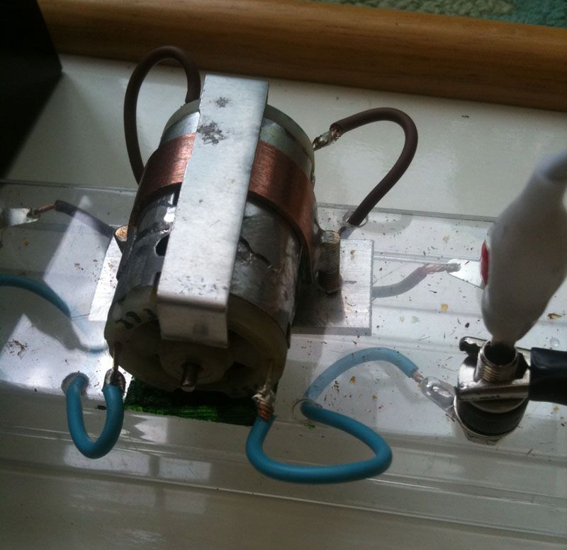
              One of the problems with the small motor is the end stator pushing out from the housing . I made a clip from some thin metal (I used some aluminum) and it works well to hold it together.

              Today I have started a run with the generator connected to the output of the motor as shown by UFO.

              Start batt voltage was 9.48V, which dropped to 7.84V on connection, which over 30mins has risen to 8.05V. Amp draw is a little less at 0.7 amps. Output across gen is 13.7V.

              Will update later.

              Regards

              John

              Comment


              • This asymetric motor (see picture), is the Brushless version of the 2 Brushed versions of Ufopolitics & Woopyjump. The power input is close to Zero (in reality we have a small leakage current). The output power depend of the diameter. In the 2 brushed versions, E field is generated beetween the 2 coils (capacitor effect) and B field by the permanents magnets.
                The force is the lorentz force, the charge is Capacity x Voltage. NO CURRENT IS NEEDED
                Laurent DAMOIS
                Attached Files

                Comment


                • Hello AmpsVolts, Good morning to All

                  Originally posted by ampsvolts View Post
                  UFO Guru..
                  Reference to post 119 you state ..
                  " Now, for sake of simplicity and not to fill it up with 20 Pairs of Coils...I have set it with just the Four Pairs that are interacting at the brush contacts..."
                  Do you mean you simplified the drawing to assist clarity...? Did you actually use 20 pairs of coils on the motor or wire it as per the simplified drawing?

                  Boy, I would love a PDF summary of the pertinent and corrected content of this and your other threads.. moving so quickly now
                  Cheers and thanks UFO.

                  Hello Ampsvolts,

                  Yes, that is exactly right, as I said it on that diagram...

                  This Motor holds a total of Twenty Pairs of Coils...it used to be almost empty with Symmetrical windings...still have the other armature winded like this...

                  I turned around 20-24 (One to two turns plus-minus, do not affect this Higher Sized and plenty coils Design Motors, the High RPM's will balance them all, so do not get too picky if at end some couple of turns will not fit) turns of 18 Gauge (awg) single wire. All Coils are exactly the same, I reduced the Generating ones in order to make them fit in CAD and not create confusion...

                  The way to wind it is just as the others, starting coil one, mark core poles involved, mark polarity (I use colors Blue-1/Red-1), so I mark the poles blue-red, then write a black marker number...I just need number one as I am practical in windings...Then Mark your Commutator starting Positive to be Red, or its shaft end...and so on...

                  I will put it all in pdf later on...I still have the "Final Stockade" to disclose, in order to terminate all witches spells for ever...Amen


                  Regards


                  Ufopolitics
                  Principles for the Development of a Complete Mind: Study the science of art. Study the art of science. Develop your senses- especially learn how to see. Realize that everything connects to everything else.― Leonardo da Vinci

                  Comment


                  • shaft length

                    Hi All
                    The shaft length on the RS motor is too short as others have stated. Please remember that this motor was selected to teach theory and winding and not so much as the motor best used for extensive testing. However, you can make it good for testing. Any kind of welding of two shafts will not work as with this high speed, even if you got it vary straight, it would woble and vibrate and testing parameters would not be good. You can however get a longer shaft and replace the short one. Cleaning the epoxy arround the rotor end and pressing out the old shaft is easy. As I also reload shells, I use my presses for this project also. Pounding them out with a hammer may cause enough of a bend as to render the old shaft unusable. I then scuff up the new shaft and epoxy in place.

                    The other thing that you can do is get drill motors of differant length shafts as most of them use the same diameter shaft and motor housing dia. Most of them ar 3 or 5 stator. Take the longest shaft and put it into a medium or shorter rotor and case. I have found several shafts in printer and copy machines that are great.

                    I prefer the drill motors in that thay are more rugged and hold up to harder testing. If the RS motors did no more than teach you how to do this tech., you got your moneys worth and then some. Thanks UFO.

                    REAL men ( and women) like real big motors.
                    Dana


                    This can be done guys.
                    "Today's scientist have substituted mathematics for experiments and they wander off through equation after equation and eventually build a structure which has no relation to reality."
                    Nikola Tesla

                    Comment


                    • Dear Damois...

                      Originally posted by Laurent DAMOIS View Post
                      This asymetric motor (see picture), is the Brushless version of the 2 Brushed versions of Ufopolitics & Woopyjump. The power input is close to Zero (in reality we have a small leakage current). The output power depend of the diameter. In the 2 brushed versions, E field is generated beetween the 2 coils (capacitor effect) and B field by the permanents magnets.
                      The force is the lorentz force, the charge is Capacity x Voltage. NO CURRENT IS NEEDED
                      Laurent DAMOIS

                      Good Day Damois,

                      That is excellent dear friend, however, I do have also a "Brush-less" version of my design...Zero Friction...Super Powered Infra Red Design or Any other desired Opto-Electronic Isolating means of Signaling through Air or Magnetic Fields sensors)...This is very simple to accomplish just because the fact that I am not reversing polarity at Motor Operation...I am just Turning On-Off...just like an Electronic Controller Oscillator Module does in a Square Signal...

                      If You could take some time...read my "ABSTRACT" at the very first post here...

                      This will open new Horizons into the world of Robotics Networks in Servo and Linear Motors Communications (Client/Server/Software/Hardware) as in many more Fields of Science as Space Age times and Air-Water-Land Vehicles.

                      However, the main issue I am, and I will continue to develop as of now until I finish in its entirety...relates to ENERGY..All other "State of the Art" sophisticated new upcoming Applications for the Industry of the "Developed Countries" could wait...till We All "balance out" an Equation that has been too long...unbalanced...Hope You will understand me...

                      Regards


                      Ufopolitics
                      Principles for the Development of a Complete Mind: Study the science of art. Study the art of science. Develop your senses- especially learn how to see. Realize that everything connects to everything else.― Leonardo da Vinci

                      Comment


                      • Originally posted by Turion View Post
                        Hmmm, By the time I made the mods on the lithe motor, there was not enough shaft sticking out to connect anything to. So can't connect to another motor or run any kind of load. I now have three other little motors besides the modified one, so could do all kinds of things, but unless I can attach to the shaft of the modified motor, I am a little stumped. Can't even measure the rpm's. Does anyone else have a shaft that is sticking out at all? Any suggestions guys?

                        Dave
                        Hi Dave. I may have a suggestion. I don't have a motor but you must have a spare stator right. Did you ever see if you could get the shaft out of the stator? Maybe you could replace the original with a hardened drill blank or piece of landing gear wire from the hobby shop. You have to get a way to load test right?
                        J

                        Comment


                        • Thanks again Dana...

                          Originally posted by prochiro View Post
                          Hi All
                          The shaft length on the RS motor is too short as others have stated. Please remember that this motor was selected to teach theory and winding and not so much as the motor best used for extensive testing. However, you can make it good for testing. Any kind of welding of two shafts will not work as with this high speed, even if you got it vary straight, it would woble and vibrate and testing parameters would not be good. You can however get a longer shaft and replace the short one. Cleaning the epoxy arround the rotor end and pressing out the old shaft is easy. As I also reload shells, I use my presses for this project also. Pounding them out with a hammer may cause enough of a bend as to render the old shaft unusable. I then scuff up the new shaft and epoxy in place.

                          The other thing that you can do is get drill motors of differant length shafts as most of them use the same diameter shaft and motor housing dia. Most of them ar 3 or 5 stator. Take the longest shaft and put it into a medium or shorter rotor and case. I have found several shafts in printer and copy machines that are great.

                          I prefer the drill motors in that thay are more rugged and hold up to harder testing. If the RS motors did no more than teach you how to do this tech., you got your moneys worth and then some. Thanks UFO.

                          REAL men ( and women) like real big motors.
                          Dana


                          This can be done guys.


                          Good Morning Dana,


                          Thanks again for helping on this, you are completely right.

                          I have been able to hand file that Radio Shack ring from the other motor to be soldered to elongate outer body, to less than a Millimeter...to make the shaft a bit longer...
                          There is a very small coupling for this motors sold at Hobby Shop stores...it has a very tiny Allen key bolt and I have two Inner Diameter types...for this motor and also for the bigger body for drills...(The TRAXXAS I wrote before of three poles). I have inserted a metal shaft through them to get them aligned, then tight the bolts and the use my 75 Watts solder Iron...and melt them with solder...it works great...but it is a very precise-Swiss watch maker operation...

                          The Hand Drills (as you've said) come in three-five poles motors, and you are completely right, they are better built for testing purposes like Dyno's and other mechanical load testing and connections to Motor-Generator Assy...their commutators mica-insulation is much better as their overall construction than this Radio Shack. So, if you guys wanna go tougher...this are the ones at a smaller scale..

                          One thing I wanted to say, is to use the hedges dedicated for this purposes when finished winding your Baby...this motors achieve speeds beyond manufacturer spec's, and we are super packing wires on this machines...so adding the hedge-retainers between poles avoids wire to pop out and mess your great work...I pack wire first with wood-plastics knife-look alike but rounded, not sharp...then slide hedge and pull it with very fine needle nose pliers...just being careful not to scratch the enamel in wire...

                          Check your windings NOT TO BE GROUNDED to the Metal Cores as you wind each Pair or Single Coils, use a Diode-Continuity Meter, from Commutator Element to Steel Core-Shaft, sometimes because of hard-tight pulls, you could crack the insulation then wire touches the metal, rubs the clear coat out and this shorts out the Coil...becoming useless...
                          Also check each Commutator Element between Start to End of each Individual Coil, making sure they are making solid contact.Then check them between right next to it other Commutator Elements/Coils...they ARE NOT SUPPOSED TO BE IN CONTINUITY between them!!

                          Learn How to check your Machine after is assembled...for Coils/Pairs Open, just connect your continuity meter at Input terminals and rotate smoothly the shaft...you will be able to tell when brush meets the "in between commutator" spacing...it "hesitates" as then it goes solid (if Analog Meter needle will drop suddenly to zero...and return fast, and Digital Meters will drop to one (1.0) as infinite reading for nano seconds...check one by one, mark start point to complete the 360 degrees round...We can not do this with Symmetric...they are always in short circuit...that is why they smoke as it shorts out...However, Asymmetric Motors could run with one or two faulty Coils (depending on total number of coils arrangement, but even the three poles could run with just Two Coils)...just like the Gas Engines could run without one or even two Cylinder firing( Eight Cylinder though, a four won't)...However, the Motor will stall at lower speeds and balance out at higher RPM's the same way...

                          Guess I expanded too much, sorry about that...


                          Regards Dana


                          Ufopolitics
                          Principles for the Development of a Complete Mind: Study the science of art. Study the art of science. Develop your senses- especially learn how to see. Realize that everything connects to everything else.― Leonardo da Vinci

                          Comment


                          • Ufo

                            Thankyou so much for all this. One thing I Noted when I took the fire spitting RS rotor appart is that Only two coils were intact. When I shut the motor off, it was running great, just spitting fire and small pieces of wire which felt like welding sparks on your skin.
                            Dana
                            "Today's scientist have substituted mathematics for experiments and they wander off through equation after equation and eventually build a structure which has no relation to reality."
                            Nikola Tesla

                            Comment


                            • Hello Dear John_G and All

                              Originally posted by john_g View Post
                              Hi Ufopolitics

                              If the permanent magnets on the small motor were to be replaced by 2 field coils, how would they be wired up? I can see that by putting the field coils in series with the motor brushes that would give the correct timing, but I'm not sure whether that would create excessive sparking at the commutator when the field is de-energized? Or as the brush can cover 2 commutator segments maybe this is not a problem as the field always has circuit to follow?

                              I'd appreciate your thoughts.

                              Many thanks

                              John

                              Good morning John,

                              I have done that in other Models, You are right about Series connection between Stator Fields and Armature Coils...So, I will tell you the way I have done it and why...it is a great question for TODAY...

                              I have been able to move the Asymmetrical Armature just by Pulsing the Stator Fields and simultaneously, the Brushes Input, but in Parallel, this way signal gets evenly distributed at both Machine Circuits, not having to suffer the Coils resistance or get noise from EM (Electro-Magnetic...NOT Electro-Motive)Fields...

                              The Parallel connection between Stator-Armature is also more suitable, in further disclosure I will make on a different type of Asymmetric Stator concept...where I will show my Model open...no Frame covered, running...and "No Two Field Coils" like you've said...I'm sick of Symmetry!!!...

                              And finally my Dear Friend, there, I will close the Loop...The Loop between my first Post here...where we were "the "silly guys" lighting up "not that great of a deal"... CFL,s and Neon's...with a single Coil and a couple of diodes...watching like little kids...that little beautiful Purple-White Plasma light...


                              Well, We ALL, will see "The Bigger Picture" then...

                              We are getting close to the end, my friend, and I feel a great relief being able to complete/download (at least in a pretty big area of most important coverage) of this Disclosure...it has been a long road...but I can see that Purple light getting brighter and brighter...


                              Regards to All


                              Ufopolitics
                              Last edited by Ufopolitics; 07-15-2012, 01:41 PM.
                              Principles for the Development of a Complete Mind: Study the science of art. Study the art of science. Develop your senses- especially learn how to see. Realize that everything connects to everything else.― Leonardo da Vinci

                              Comment


                              • Originally posted by JohnStone View Post
                                Regarding reversal or not we need to decern two possibilities of reversing a magnetic field.
                                1. We can fight frontally against and will have the effect like shaking a heavy flywheel in our hands. In the end we can force a nail into wood if we use this wheel as a hammer. - Not very smart. Shure, we get a reversal but in the expense of discarding all energy stored before and filling another new chunk of energy again and again.

                                2. We can reverse polarity by rotating the field in another direction. So we get a reversal without depletig the magnetic energy before. We opreate a flywheel in a genuine art.

                                @Ufo and Lamare: Is there a common view here?
                                ~o0o~
                                Yes, that is about the idea. It is very hard to connect al the dots theoretically, but I see a certain analogy with Milkovic' pendulum:

                                Veljko Milkovic - Home Page - Official presentation of the researcher and inventor Veljko Milkovic

                                I appears to me that the way UFO is working, is indeed much more like working with the already present field of the permanent magnet, instead of fighting it frontally.

                                Just like with Milkovic' pendulum, you are fiddling with the balance of the system, which enables you to extract energy out of a "DC" field, either a permanent magnetic field or the gravity field in Milkovic' case.

                                I suspect that when you analyze this completely trough, it can somehow be seen as "parameter variation", whereby you vary some aspect of a system by which you introduce asymmetry. This means that you have an oscillating system (rotation is one form of oscillation) whereby you change a parameter, like for example the inductance or capacitance of the oscillator or in the case of Milovic the length of the long arm.

                                The idea is then that the changing of that parameter takes you very little energy, while it introduces a disbalance in the oscillator which enables the oscillator to pick up energy from the aether. That is what Bearden refers to as "regauging".

                                This has been theoretically described in Russian by Mandelstam and Papalexi in the 1930s, a/o referred to by Dollard, which has been recently translated:

                                Directory contents of /pdf/Reference_Material/Mandelstam_Papalexi/

                                In the case of these motors, you have a rotor which is asymmetric. Since the field of the PM is DC, but it is a dynamic force, it looks like you influence the path the field of the PM takes by means of firing a coil on the rotor.

                                As far as I can tell, there is one pole that is (almost) completely within the PM, while there are two that are in a process of magnetizing/demagnetizing because of leaving/entering the PM. Since the PM is DC and there is one pole (almost) completely within the PM's influence, the magnetizing/demagnetizing of the other poles must be (largely) in balance.

                                Now since you influence this balance by the firing of the coil and the PM is DC, it appears you can see that influencing as some parameter change indeed. You could perhaps see it as akin to lowering the "magnetic resistance" of the pole you want to be attacked by the PM.

                                So, I do see some theoritical basis on why this system could be COP > 1, but I doubt if you will be able to make it self running just on the generator windings alone. Because if indeed the working principle is parameter change, then all the energy you can get back from the generator winding is the energy spent on changing the parameter, the "magnetic conductivity" of one of the poles.

                                However, that pole is rotating within a magnetic field of the PM, which makes things very complicated. So, there are also arguments that the rotator coils could pick up some energy from that field. However, if the motor is properly constructed, the idea is that most of the magnetic force is turned into useable torque.

                                To sum this up: I do see some very interesting possibilities that this design might cause a revolution, but practice will have to tell. Theory can only get you so far....

                                Comment

                                Working...
                                X