Announcement

Collapse
No announcement yet.

My Asymmetric Electrodynamic Machines

Collapse
X
 
  • Filter
  • Time
  • Show
Clear All
new posts

  • Generator Output

    Hi Guys,

    I would like to confirm my observations with the generator output of the asymmetric motor. While powering the motor through the input connection, any load I connect to the output generator connections causes an increase in current draw from my source 12v battery. Has anyone else noticed this?

    Btw, I'm getting around 6v on the generator output and 18 volts when using the jumper across the motor input and generator output(As shown by UFO). I was under the impression that the generator output was isolated from the input. If its not isolated what is the benefit of the generator output while running the motor?

    Keep in mind, I have not run any tests running the asymmetric motor solely as a generator, just in the motor/generator mode. Hopefully Turion will have some data soon on the generator side of things.

    In any case, this is just the observation of a novice. I just want to confirm if I'm off track or if my findings are consistent with others who have completed the replication.

    Thank you

    Comment


    • Originally posted by john_g View Post
      @UFO
      May I ask how you would wind a VW generator armature? I know many here brought these to try and replicate the lockridge device. It has 30 slots. and maybe use 2 pairs of field coils?..
      Same question from my side!
      This is a drawing of the generator mentioned.
      The left two are the old 6V models not being compatible to the right hand side 12V model.
      Pic1
      Pic2
      Pic3
      PIC4

      Jst got one at ebay: 14V / 32A / 28 bucks.
      Last edited by JohnStone; 07-16-2012, 07:48 PM.
      Experts spend hours a day in order to question their doing while others stopped thinking feeling they were professionals.

      Comment


      • Originally posted by darkoni View Post
        Hi Guys,

        I would like to confirm my observations with the generator output of the asymmetric motor. While powering the motor through the input connection, any load I connect to the output generator connections causes an increase in current draw from my source 12v battery. Has anyone else noticed this?

        Btw, I'm getting around 6v on the generator output and 18 volts when using the jumper across the motor input and generator output(As shown by UFO). I was under the impression that the generator output was isolated from the input. If its not isolated what is the benefit of the generator output while running the motor?

        Keep in mind, I have not run any tests running the asymmetric motor solely as a generator, just in the motor/generator mode. Hopefully Turion will have some data soon on the generator side of things.

        In any case, this is just the observation of a novice. I just want to confirm if I'm off track or if my findings are consistent with others who have completed the replication.

        Thank you
        Hi darkoni
        "I connect to the output generator connections causes an increase in current draw from my source 12v battery"

        What is the amps-volts difference?
        Thank you

        Comment


        • Originally posted by Ufopolitics View Post
          Hello to All,

          Now before we have been just connecting Pairs to single elements of Commutators matching "perfect"...like Five(5) Pairs to Five (5) Commutator Elements top-below...Now, it could be done "Asymmetrically" also...

          Like if We have a 12 Pole Armature...or a 10 Pole Armature...

          We could use in a 12 Pole Armature, a combination of what I call the "Sacred Geometry Design", where we wind three Pairs of Coils configuring a "Dual Delta Star" or a David Star...now, three Pairs of Coils will give Us exactly Six terminals (Two per Pair) for 12 X2 Commutator Elements...so, it shouldn't work right?


          Well it does, We just have to "blend" commutator elements in groups of Three, (just wire them up through the hooks)...then we will get Three separated continuous elements per commutator...

          This will need to do a bit of work right next to each separation of groups of three copper comm elements...open them a bit more the copper, to make space a bit wider by filing them spreading the segment spacing (to avoid heavy arcing, therefore damage to metal plates)

          The same thing We could do with a 10 Pole Armature...using a Dual Pentagon Opposed, Design...using every two copper contacts joined at each commutator, and we have 5 Pairs of Coils.

          This Motors have incredible torque, I mean great...but besides that, the times of Charging-Discharging are larger in time of being "On"(charging)...as also at Discharge times, that is why we most file the in-between commutator plates a bit wider. Otherwise they will discharge to next randomly closer element not in "Timing" to be done.


          [IMG][/IMG]

          On this particular set-up,

          Dark Blue (N) and Red (S) are Pair #1 (notice they are Parallel.)
          Aqua Blue (N) and Orange (S) Pair# 2
          Green (N) and Yellow (S) Pair # 3


          Regards to All


          Ufopolitics
          How did you know I was coiling a 12 pole rotor I found today?

          Did you make a mistake with the colors at the generator commutator?
          I am missing the colors red, orange and yellow.
          Where does the black spots come from?

          Bert

          Comment


          • Dear Bert...I knew...

            Originally posted by bbem View Post
            How did you know I was coiling a 12 pole rotor I found today?

            Did you make a mistake with the colors at the generator commutator?
            I am missing the colors red, orange and yellow.
            Where does the black spots come from?

            Bert
            Hello Dear Bert,

            The Commutator Elements are coded on Blue Derivatives only ...it is written on the Diagram, below center...didn't see it?

            Now, it is understood All related South Ends will connect to All Bottom Commutator corresponding Color Codes, as I wrote in my Post below...

            The Black space at Comm are the SEPARATIONS between joint elements connected in series...That I wrote: MUST BE FILED TO INCREASE THE GAP...

            Regards


            Ufopolitics
            Last edited by Ufopolitics; 07-16-2012, 08:11 PM.
            Principles for the Development of a Complete Mind: Study the science of art. Study the art of science. Develop your senses- especially learn how to see. Realize that everything connects to everything else.― Leonardo da Vinci

            Comment


            • high guys im new to all this but very interested i would love to try make one of these motor starting small will a 3 armature motor first but not very good at following text instructions has anyone got a video on them making one or a step by step ?

              Comment


              • Hello Darkoni

                Originally posted by darkoni View Post
                Hi Guys,

                I would like to confirm my observations with the generator output of the asymmetric motor. While powering the motor through the input connection, any load I connect to the output generator connections causes an increase in current draw from my source 12v battery. Has anyone else noticed this?

                Btw, I'm getting around 6v on the generator output and 18 volts when using the jumper across the motor input and generator output(As shown by UFO). I was under the impression that the generator output was isolated from the input. If its not isolated what is the benefit of the generator output while running the motor?

                Keep in mind, I have not run any tests running the asymmetric motor solely as a generator, just in the motor/generator mode. Hopefully Turion will have some data soon on the generator side of things.

                In any case, this is just the observation of a novice. I just want to confirm if I'm off track or if my findings are consistent with others who have completed the replication.

                Thank you

                Hello Darkoni,

                I would like to confirm my observations with the generator output of the asymmetric motor. While powering the motor through the input connection, any load I connect to the output generator connections causes an increase in current draw from my source 12v battery. Has anyone else noticed this?
                But of course Dear Darkoni, the Motor is going to draw a higher current from your source!!
                I mean, this Motors Transfer the Energy and deliver a Mechanical Power out...for free, while supplying an output to your source also...I mean...were you expecting more from this little motor?

                Ok, and this goes to anyone measuring-testing-loading this Small Motors:


                Whenever you guys "Add" a Load, please, specify, exactly, to the point,...What kind of "Load" are you trying-stressing out, this "Conversion, Adapt" of Five (5) U.S Dollars and Ninety Nine Cents (0.99) Motors..It absolutely will help...Thanks.


                Btw, I'm getting around 6v on the generator output and 18 volts when using the jumper across the motor input and generator output(As shown by UFO). I was under the impression that the generator output was isolated from the input. If its not isolated what is the benefit of the generator output while running the motor?
                Dear Darkoni,

                Did you watch the great video from Mr. Lindemann Motor Secrets?
                No?
                Then you should watch it is a great video!..It will give you "Solid Grounds" to be able to Test any Motor the right ways as also to be able to "Evaluate" properly a NOVEL DESIGN..

                Yes?
                Then you should have learned that Effective Armature Voltage (Eff V) in ANY given Motor is given by the Input Values (Source)=Ea MINUS(-)Ec (or C EMF) Are We agreeing up to now?...
                No?
                Then you should watch the video again...
                Yes?
                Then, will you understand that NOW, we are ALL having a POSITIVE VALUE that WOULD NOT subtract ANYMORE in "just"... a pretty short period of One Hundred and Thirty Two Years (132)
                Isn't that for you... some... maybe, I mean, just a bit of GAIN NOW?...
                Or you rather do like Symmetry does?...

                Because, then you could also make "another test"...grab Negative-Positive Terminals of your Six Volts (+6V) now positive output...and insert it reversed to your Input Values, Source or Ea, meaning where Positive is, insert your negative out, and where Negative is....insert your positive out...then, you may have a "decrease in Amperage"...a weaker and very HOT Motor...but a "DECREASE IN AMPS"...Oh, and do not try to run the "torque" test then...it will melt...
                I mean, if that is what you are looking for...go ahead and that easy, it will "solve" the whole "problem" of watching very "Low Amperage"


                Regards


                Ufopolitics
                Principles for the Development of a Complete Mind: Study the science of art. Study the art of science. Develop your senses- especially learn how to see. Realize that everything connects to everything else.― Leonardo da Vinci

                Comment


                • Hello Dear John Stone

                  Originally posted by JohnStone View Post
                  Same question from my side!
                  This is a drawing of the generator mentioned.
                  The left two are the old 6V models not being compatible to the right hand side 12V model.
                  Pic1
                  Pic2
                  Pic3
                  PIC4

                  Jst got one at ebay: 14V / 32A / 28 bucks.
                  Hello to both Johns..Mr. Stone and Mr. G,


                  That looks like a great Machine to convert, now could someone here post me a pic of Above Top View without upper cap, but displaying the brush position, versus stators, and also armature clearance for wiring space...in that diagram can not see it clear..
                  Otherwise it seems it has room for a second comm...

                  If it has 30 Poles, it is divisible of five (5) and three(3)...therefore, it should work with either of the two first simple designs I have posted...However depends on stator Diameter, angle of brushes, etc...This primary numbers are meant to be expanded into their multiples of...However, they need to be set on CAD, make a Group of all Armature components and rotate it at every degree...with a virtual "marker", to know where you started...What you guys will be looking for is that at ANY point of rotation, Input-Output Coils arrangements COINCIDE AT EXACTLY 180 Degrees, if it does...it is not good, throw combination and try next...and most of times this happens at just Pair of Coils # 1 at Input, then look "WHO" is at your Output "knocking the door" or just touching comm elements...
                  Now, there could be just ONE COIL OF THE PAIR ALIGNED, but if other is NOT, it will work...That creates a different Asymmetrical Magnetic Pattern...not canceling to zero...it configures something like a "Y"...

                  Hope you guys understood me, let me know , please


                  Regards


                  Ufopolitics
                  Principles for the Development of a Complete Mind: Study the science of art. Study the art of science. Develop your senses- especially learn how to see. Realize that everything connects to everything else.― Leonardo da Vinci

                  Comment


                  • hi all

                    just going on my apprentice schooling

                    and here a pix of my 3 poles modified "Igarashi motor"

                    it works really well

                    The winding is 3 X 100 turns with 0.2 mm copper wire , the same as per my 5 pole replication

                    the torque is really strong and the generator is quite high.

                    i know that all this is subjectiv but it is my feeling so far

                    for more measured resutls , please be patient, or much better replicate and give us details

                    always at full enthusiasm on this project


                    good luck at all

                    Laurent
                    Attached Files

                    Comment


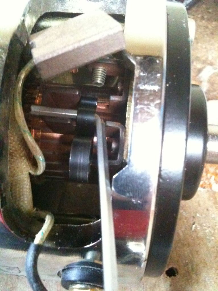
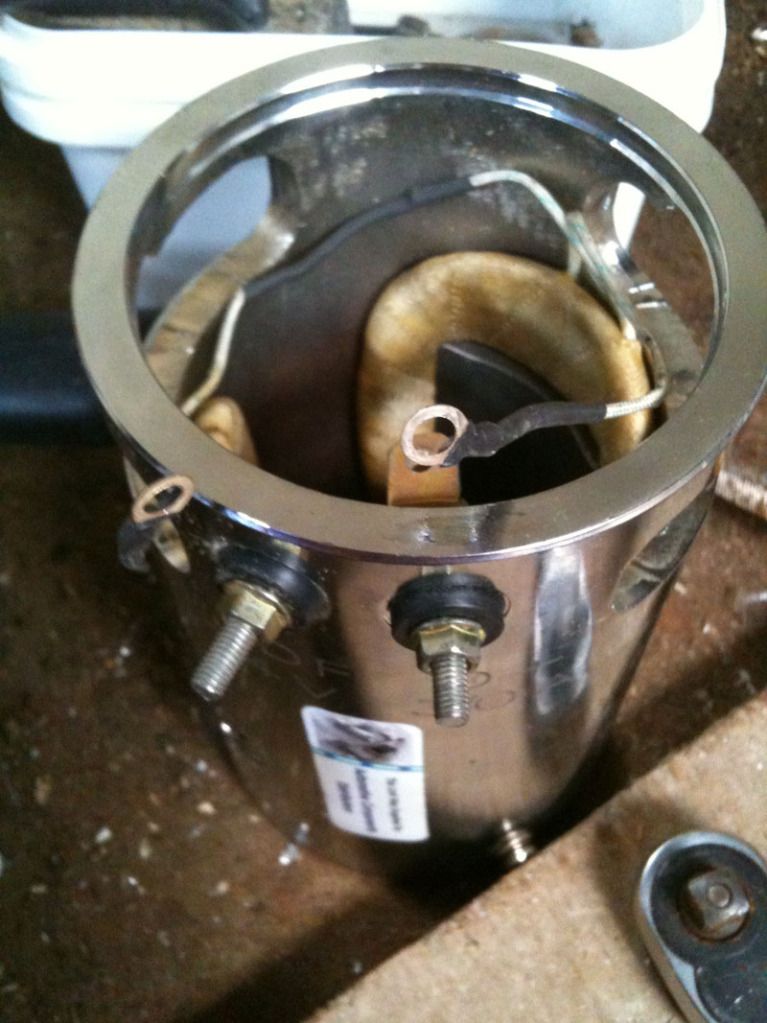
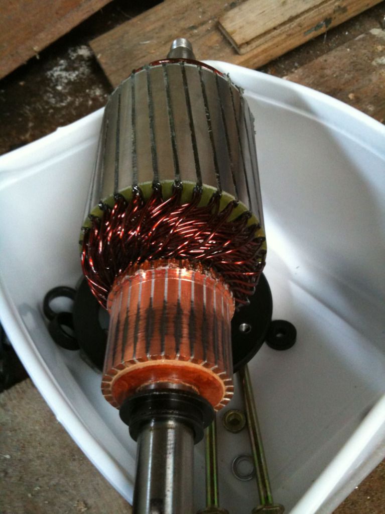
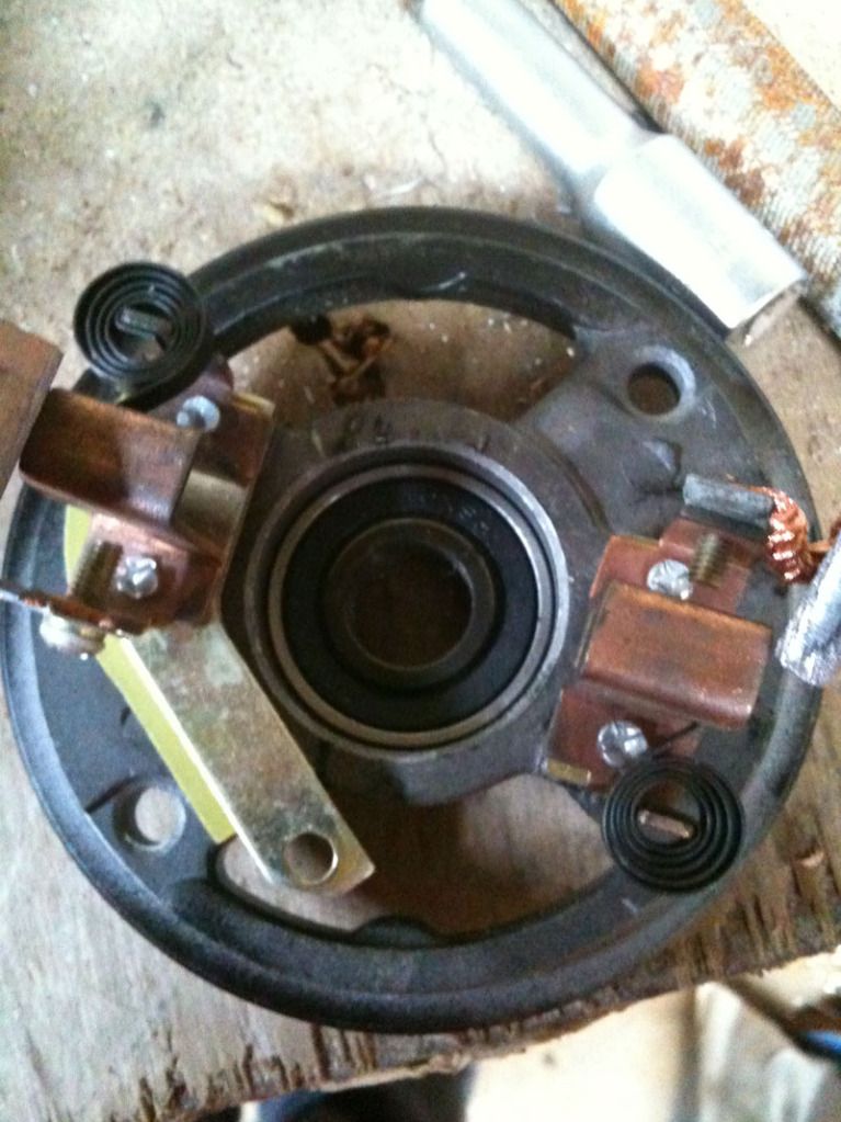
                    • VW Pics

                      Hi UFO

                      Here are some VW pictures, that I already had.

                      Regards

                      John


                      Comment


                      • About This "conversions" Here...

                        Hello to ALL,

                        I want to say this, as you guys understand what we are all doing here...

                        We are "converting" machines that were conceived and designed to run Symmetrically, this means their Rotor (Armature), dispositions of Stators, Brushes and number of Poles arrangement size and separations...were calculated to fit this Methodologies...
                        Now, what we are all doing here, is "picking up garbage, rubbish, junk stuff" not SPECIFICALLY DESIGNED to FULFILL in a 100% BASIS, the WAYS ASYMMETRY REALLY OUTPUTS AND PERFORMS AT MAXIMUM LEVELS...

                        We are all, patching, stitching a very Old piece of sh** Machine...trying to make it run as a V12 Lamborghini...Diablo

                        Figure Out this example...

                        Let's say there is a guy in South America, ...down below the old Continent, that can make "LOOK ALIKE", your OLD CAR, that is a very OLD beaten up, and not functioning right...Volks Wagen...and the Guy tells you to bring several pieces of the same car, ..and He will try to deliver back to You a "look alike" MERCEDES BENZ S600, Convertible...His tooling are also obsolete...old type of Instruments Not Designed to even create a VW...but He likes his job...and hammers that Beetle like thaere is no tomorrow...till He thinks is just like an S600...Then throw a paint job in it...

                        Now, would you expect a perfectly new...MB S600, as just driven out of a German Factory...zero miles...and perform as such?

                        No, right?

                        So, therefore, please, do not expect out of this "Conversions" will deliver a MB...

                        I am playing here the "role" of that guy down south...converting your old VW, broken and beat up...into a stylish state of the art...machine...and showing you how to beat it up...

                        So do not complaint to me please...if you find out that your Mercedes is just a piece of Sh**...
                        Be Happy... , and very "pleased"... that "at least" it runs better than before...when it was a cooking range, and Oil, water -Gas leakier..and tended to overheat every quarter mile...stall and leave you in the middle of the road...

                        So, take it easy...and drive it...and enjoy it.


                        Thanks and regards to all


                        Ufopolitics
                        Principles for the Development of a Complete Mind: Study the science of art. Study the art of science. Develop your senses- especially learn how to see. Realize that everything connects to everything else.― Leonardo da Vinci

                        Comment


                        • Originally posted by Ufopolitics View Post
                          Hello Darkoni,


                          But of course Dear Darkoni, the Motor is going to draw a higher current from your source!!
                          I mean, this Motors Transfer the Energy and deliver a Mechanical Power out...for free, while supplying an output to your source also...I mean...were you expecting more from this little motor?

                          Ok, and this goes to anyone measuring-testing-loading this Small Motors:


                          Whenever you guys "Add" a Load, please, specify, exactly, to the point,...What kind of "Load" are you trying-stressing out, this "Conversion, Adapt" of Five (5) U.S Dollars and Ninety Nine Cents (0.99) Motors..It absolutely will help...Thanks.


                          Dear Darkoni,

                          Did you watch the great video from Mr. Lindemann Motor Secrets?
                          No?
                          Then you should watch it is a great video!..It will give you "Solid Grounds" to be able to Test any Motor the right ways as also to be able to "Evaluate" properly a NOVEL DESIGN..

                          Yes?
                          Then you should have learned that Effective Armature Voltage (Eff V) in ANY given Motor is given by the Input Values (Source)=Ea MINUS(-)Ec (or C EMF) Are We agreeing up to now?...
                          No?
                          Then you should watch the video again...
                          Yes?
                          Then, will you understand that NOW, we are ALL having a POSITIVE VALUE that WOULD NOT subtract ANYMORE in "just"... a pretty short period of One Hundred and Thirty Two Years (132)
                          Isn't that for you... some... maybe, I mean, just a bit of GAIN NOW?...
                          Or you rather do like Symmetry does?...

                          Because, then you could also make "another test"...grab Negative-Positive Terminals of your Six Volts (+6V) now positive output...and insert it reversed to your Input Values, Source or Ea, meaning where Positive is, insert your negative out, and where Negative is....insert your positive out...then, you may have a "decrease in Amperage"...a weaker and very HOT Motor...but a "DECREASE IN AMPS"...Oh, and do not try to run the "torque" test then...it will melt...
                          I mean, if that is what you are looking for...go ahead and that easy, it will "solve" the whole "problem" of watching very "Low Amperage"


                          Regards


                          Ufopolitics
                          With all due respect to you and the replicators. They didn't know what to expect from the voltage test. You make the voltage increase sound so very important. So it was a test that had to be done because it hasn't up till now. It would have been wonderful if there would have been different results than what you would expect from a standard motor / generator. OK so now we know not to expect more than a voltage increase measurement, unless it's sed for some kind of feedback or something down the line. I thing the guys did a good job to get to the point where they could make the test. Incidentally I wouldn't expect someone who may never build more than this little motor to study Lindemann's video and try to duplicate a similar way to test a little motor like this. Any kinetic load that can be duplicated from the original to the modification would tell whether the modification is better than the original. A fan blade or propeller are excellent and inexpensive. Torque tests are next then, isn't that correct? But let me ask first. It sounds like you are saying that these little motors can't be expected to show performance results? If this was just a lesson to see if a person could duplicate the wind, then we should have known that from the beginning. You said yourself that this motor would run stronger and be harder to stop than the original. I hope so but can it be done without pounding the motor with more current than the original motor. You also said you where anxious to see people start their tests. Let me know if the little motors aren't suitable to see at least some promising results in such a comparison. I won't have to bother winding my stator then.
                          John H.

                          Comment


                          • Originally posted by Ufopolitics View Post
                            ... could someone here post me a pic of Above Top View without upper cap, but displaying the brush position, versus stators, and also armature clearance for wiring space...in that diagram can not see it clear....
                            I will get that pet next week and post pics of those parts. Extension of the housing seems to be required.
                            Experts spend hours a day in order to question their doing while others stopped thinking feeling they were professionals.

                            Comment


                            • Originally posted by JohnStone View Post
                              I will get that pet next week and post pics of those parts. Extension of the housing seems to be required.
                              Hi John/UFO

                              May sound a bit off beat, but what about putting the armature in a lathe and dividing the commutator into 2 equal sections by cutting out a central ring - thus 2 commutators. Then drilling small holes, inline with the shaft through the commutator insulation, below each bar, to then allow connection to be made?

                              Regards

                              John

                              Comment


                              • Trouble-shooting 3 Pole Conversion

                                Hi Guys,
                                I have 2 nice 5-pole DC motors to convert. First, I thought I'd try 2 cheap 3 pole motors from 2 identical dollar store toys.
                                I wired 'em up as per UFO's specs, modded the housing and put the commutators at each end.
                                But no movement at all, even with a 9 V battery.
                                I thought it could be:
                                - rotor stuck against a stator magnet (should I grind rotors it down for more clearance?)
                                - magnets reversed/backwards (is this possible?)

                                I'm bummed out; thought I had this in the bag. I can post pics as well. Any troubleshooting suggestions appreciated.

                                Otherwise, I'll start on the 5 pole.

                                Bob

                                Comment

                                Working...
                                X