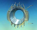
Announcement

Collapse
No announcement yet.

My Asymmetric Electrodynamic Machines

Collapse
X
 
  • Filter
  • Time
  • Show
Clear All
new posts

  • stator pattern

    Hi UFOpolitics,
    Another great video but i gotta agree with Turion that its hard to tell the winding pattern for the stator. I'll try to watch again and re examine it. But very tuff to see. Thanks for taking the time to put this together for everyone!!

    Comment


    • Stator Pattern...

      Originally posted by pmazz850 View Post
      Hi UFOpolitics,
      Another great video but i gotta agree with Turion that its hard to tell the winding pattern for the stator. I'll try to watch again and re examine it. But very tuff to see. Thanks for taking the time to put this together for everyone!!

      Hello Pmazz850,


      I had several requests here, and in YT Channel's comments and private messaging about to make a way for people to wind all this different configurations...shown in a "simple way"...Now, since I am a bit knowledgeable about 3D CAD Animations, I have thought of making this by using the same 3D curves that defines the extrusion of wiring's...to add point lights to all of them, in order for light to travel along that three dimensional curve...so, all you guys will have to do is to "follow the light path"...and since videos are public and downloadable, you could play it as much as you like back and forth... And of course this will apply to Stators and Armatures...However, bare with me here, since this work I can not afford to "order it" to "Industrial Light and Magic" or to any other FX Company out there...too expensive!!...

      However, I will repeat to you and Turion...
      The Asymmetrical Stator, is nothing more than a Single Wound Coil...that I used this Fiberglass Structure to be able to create an "Opening" to allow Armature in...since Motor Axis only rotates Perpendicular to Coil Center Axis, just like a [+]...there is no way it will work otherwise...

      The Fins are to be able to go up, then go down on first LEVEL, LEVELS are configured by Upper-Lower Fins, totaling Six Levels,that includes the Stator Mounting Ends at each side ...I have wound around 15 turns on each LEVEL then getting to next LEVEL, and so on... then come back in a second layer (In the 3D Animation I made the second layer as the higher wires...not to create confusion) following same pattern...till I reached the starting point...Now, in order to "compensate" magnetic pattern, We must do the Layers as equally balanced as we can, related to the Front and Rear Armature Openings or "Mouth" we wrap around to go next LAYER...towards each side of the windings...

      Of course it could be done much bigger than this...of course more turns...therefore more power, more energy out...but then realize you guys need a bigger "Switcher" to excite a bigger Coil...as everything in life "must be balanced"...or then Nature will do it...

      Regards


      UFO
      Last edited by Ufopolitics; 07-24-2012, 05:13 PM.
      Principles for the Development of a Complete Mind: Study the science of art. Study the art of science. Develop your senses- especially learn how to see. Realize that everything connects to everything else.― Leonardo da Vinci

      Comment


      • Just for interest only


        Hi UFO and all, I have been watching this thread with interest and UFO I believe what you say and I did build your little motor but had a bit of an accident when I left it running at over 20K rpm and a section of the commutator flew off, not a good motor to convert but all I had at the time.

        Here for interest is a solid state over COP 1 which if you look is similar to what you are doing. I am not going to explain any of it as it will be obvious to those that are in the know and I am sure you will see the parallel.

        This was replicated in a lab in Detroit under my supervision via video conference some two years ago. I have not done any more with this at the moment due to my other work and personal problems. This circuit works but has a problem, IT DESTROYS THE BATTERY even though the current draw was a zero negative (0-), the load max was on test 24 leds of 32ma each, the battery lasted three days (7ah 12v).

        I would have liked to replace the output transformer with your motor, but until I can lay my hands on two more motors to convert, it will have to wait.

        Keep up the good work, I like it very much

        Mike
        Last edited by Michael John Nunnerley; 01-06-2014, 11:35 AM.

        Comment


        • Asymmetrical Stator 3d Cad Animation Only

          ASYMMETRICAL STATOR 3D CAD ANIMATION ONLY, EXCEPT A BACKGROUND SONG TO RELAX THE VIEWING...
          Can always turn off volume in case you do not like it...

          [IMG][/IMG]

          ASYMM ANIM ONLY SOUND - YouTube


          Regards to ALL


          U.F.O.
          Last edited by Ufopolitics; 07-24-2012, 06:33 PM. Reason: add YT link
          Principles for the Development of a Complete Mind: Study the science of art. Study the art of science. Develop your senses- especially learn how to see. Realize that everything connects to everything else.― Leonardo da Vinci

          Comment


          • Thanks Michael,

            Originally posted by Michael John Nunnerley View Post
            [ATTACH]11810[/ATTACH]

            Hi UFO and all, I have been watching this thread with interest and UFO I believe what you say and I did build your little motor but had a bit of an accident when I left it running at over 20K rpm and a section of the commutator flew off, not a good motor to convert but all I had at the time.

            Here for interest is a solid state over COP 1 which if you look is similar to what you are doing. I am not going to explain any of it as it will be obvious to those that are in the know and I am sure you will see the parallel.

            This was replicated in a lab in Detroit under my supervision via video conference some two years ago. I have not done any more with this at the moment due to my other work and personal problems. This circuit works but has a problem, IT DESTROYS THE BATTERY even though the current draw was a zero negative (0-), the load max was on test 24 leds of 32ma each, the battery lasted three days (7ah 12v).

            I would have liked to replace the output transformer with your motor, but until I can lay my hands on two more motors to convert, it will have to wait.

            Keep up the good work, I like it very much

            Mike
            Hello Michael,

            Thanks, sorry about what happened to your motor...now this to be modified motors.. are only designed structure wise to stand the specific RPM's stated, which most of times can not even reach those levels...Therefore, I recommend after a Mod Model has been checked, to make sure to wrap it, use hedges between poles, adding epoxy at coils, ONLY if wire is too loose...as also Commutators and Housings need to become more secured and robust...

            I will take a look at your work now (that by the way, I have looked at your previous designs-work, and I like them very much)...


            Kind regards


            Ufopolitics
            Last edited by Ufopolitics; 07-24-2012, 06:36 PM.
            Principles for the Development of a Complete Mind: Study the science of art. Study the art of science. Develop your senses- especially learn how to see. Realize that everything connects to everything else.― Leonardo da Vinci

            Comment


            • Nice SEPIC setup.

              I like you're SEPIC setup a lot I was thinking about something like that after you described it originally, and I had come up with the same thing except you actually have a circuit and it is not only nice, it works.

              So I have two questions about C1, it should be low ESR, so silver mica would be one of the best choices, glass or one of the poly dielectrics would be some of the next best choices? Basically, high Q capacitors is what I am getting at (Low loss dielectric, low resistance plates?). Wikipedia - Q Factor

              My next question is, the about the size of C1. At least how much energy should it store? Should it's capacity be large enough that the mosfet starts and stops the C1 discharge (C1 never fully discharges and we have full control over duty cycle), or is there a more passive balance that might save our mosfets a little pain by turning off less current (coming from C1)?

              I hope my extra definitions I always seem to add to my questions don't get in the way, I feel kind of comfortable with some of this but I feel I have loose ends in my facts that with a little extra wording on my part would help me have a more useful grasp and ultimately, understanding. I hope it is helpful to others and does not detract from anyones understanding or time.

              One of my goals is to be able to know the parts and how to make them and from what to make them of, I would like to see a junkyard looking more like a goldmine.
              Combined with state of the art switching and timing you can find in power supplies, monitors/TVs (CRTs have quite a bit of magnet wire, also, check the front of the tube under the back cover and at the back of the tube, always one big one based on the size of the screen sometimes a small one toward the back both locations found wrapped in a single coil by black electrical tape, several hundred feet in a 17", 5 minutes, beware of the flyback, use all of the kill.) The forests are starting to look a little different, but with our new knowledge we can make good use of what we have, while we return what we lost.

              Thank You,
              matt
              Last edited by codeboundfuture; 07-24-2012, 08:16 PM.

              Comment


              • Hi everybody.
                Here is little clip of the setup I am working on right now.
                Pulse Motor - Gap-Power style setup
                UFO, do You think it is asymmetric?

                I this short clip I am testing this new setup according to Gap-Power_com experiments.
                The RPM here is 1250, the power is being supplied by 12V 7.5 AHr battery.
                The current draw is measured as a voltage drop on 0.1 Ohm shunt resistor and its value is 370 mA maximum. There are 6 N52 neodymium magnets on the rotor, the driving coils are bilfilar in series, 2 in series, 4 Ohms total resistance and about 15 mH inductance together.
                A Hall sensor turns on a MOSFET transistor on an approaching magnet to neutralize repelling force from the stack of magnets behind the driving coils that push the rotor at Top Dead Center when the power is off.
                In that moment the coil becomes a generator coil as the core (magnetite powder + iron powder + resin) switches polarity and returns much of the energy back to the battery.
                This can be seen on the scope trace as the lover curve bump, below the marker line.
                It seems to be a very efficient motor, the cores do not heat up, more testing to come...
                “ THE PERSON WHO SAYS IT CANNOT BE DONE SHOULD NOT INTERRUPT THE PERSON DOING IT ! ”

                Comment


                • LED Test

                  Hello. I went to the Auto Parts store to look at LED bulbs and what they had there looked like an array of standard LED's an maybe a resistor or two. Instead of spending $16.00 I decided to make my own array. I put 12 LED's in series then started lighting them one by one while adjusting RPM of the RS Mod appropriately. As I went from 1 through 12 I got really excited because the Amp draw was not going up at all as I went through them. So I had 12 LED's going with no change of current. I switched to the two 12 volt panel incandescent and the current changed by 200 ma. I thought finally, but then my fun was spoiled when I hooked the array up to the power supply and it only drew 10 ma. I always wondered how Rusty shows off lighting all those LED's from a little Joule Thief. OK so I put some of the LED's in series parallel and was drawing 200 ma over the run voltage of the RS Mod. So I guess the question would be is it any different with the Auto bulb? Maybe I'll go buy one after all but now I'm not sure about the bulb. I thought I've seen SMD auto bulbs. Anyway I tried a few experiments. I scoped the output of the RS Mod and could see something that resembled an h wave with some voltage spikes about 10-20 volts higher than run voltage. The battery charged from 12.5 volts to 14 but this is easy since it was charged to 14.7 the other day and rested. The battery bubbled but the current draw on the RS Mod was about 700 ma over the run current. I did the battery hook up for another reason though. I put a sniffer coil on the battery and found a familiar looking bell curve similar to SSG experiments.
                  UFO Experiments :: Snifferonbattery.jpg picture by DadHav44 - Photobucket
                  John H

                  Comment


                  • Hello Dad Hav

                    Originally posted by DadHav View Post
                    Hello. I went to the Auto Parts store to look at LED bulbs and what they had there looked like an array of standard LED's an maybe a resistor or two. Instead of spending $16.00 I decided to make my own array. I put 12 LED's in series then started lighting them one by one while adjusting RPM of the RS Mod appropriately. As I went from 1 through 12 I got really excited because the Amp draw was not going up at all as I went through them. So I had 12 LED's going with no change of current. I switched to the two 12 volt panel incandescent and the current changed by 200 ma. I thought finally, but then my fun was spoiled when I hooked the array up to the power supply and it only drew 10 ma. I always wondered how Rusty shows off lighting all those LED's from a little Joule Thief. OK so I put some of the LED's in series parallel and was drawing 200 ma over the run voltage of the RS Mod. So I guess the question would be is it any different with the Auto bulb? Maybe I'll go buy one after all but now I'm not sure about the bulb. I thought I've seen SMD auto bulbs. Anyway I tried a few experiments. I scoped the output of the RS Mod and could see something that resembled an h wave with some voltage spikes about 10-20 volts higher than run voltage. The battery charged from 12.5 volts to 14 but this is easy since it was charged to 14.7 the other day and rested. The battery bubbled but the current draw on the RS Mod was about 700 ma over the run current. I did the battery hook up for another reason though. I put a sniffer coil on the battery and found a familiar looking bell curve similar to SSG experiments.
                    UFO Experiments :: Snifferonbattery.jpg picture by DadHav44 - Photobucket
                    John H

                    Hello Dad Hav,

                    [QUOTE]
                    Originally posted by DadHav View Post
                    Hello. I went to the Auto Parts store to look at LED bulbs and what they had there looked like an array of standard LED's an maybe a resistor or two. Instead of spending $16.00...[...]
                    I was referring to the Automotive LED Bulbs that replaces the typical 1156 (one filament)...same socket, different lighting system electronics...was that $16.00?!...Geez!, what Auto Parts did you go to...a Car "Boutique"?...

                    I put 12 LED's in series then started lighting them one by one while adjusting RPM of the RS Mod appropriately. As I went from 1 through 12 I got really excited because the Amp draw was not going up at all as I went through them. So I had 12 LED's going with no change of current. I switched to the two 12 volt panel incandescent and the current changed by 200 ma. I thought finally, but then my fun was spoiled when I hooked the array up to the power supply and it only drew 10 ma.
                    Dad Hav...Dad Hav...You should have check first with your nice Power Supply, to see if "worth the try"...it would have save you some of your precious time!


                    I always wondered how Rusty shows off lighting all those LED's from a little Joule Thief.
                    ...So funny am LMFAO ...

                    OK so I put some of the LED's in series parallel and was drawing 200 ma over the run voltage of the RS Mod. So I guess the question would be is it any different with the Auto bulb? Maybe I'll go buy one after all but now I'm not sure about the bulb.
                    It would help Us all...(just a bit, you know...) if You will tell Us...about the RPM Drop DIFFERENCE on Machine with both type of Loads...I mean, it will help Us just a bit...to tell you if there is "any difference in LED versus the Incandescent Bulb"...


                    Maybe I'll go buy one after all but now I'm not sure about the bulb. I thought I've seen SMD auto bulbs.
                    Buy it if Machine "did not even feel" the LED's when you test them... but please do not go to that "Car Boutique" ...definitively is a rip off...


                    Anyway I tried a few experiments. I scoped the output of the RS Mod and could see something that resembled an h wave with some voltage spikes about 10-20 volts higher than run voltage. The battery charged from 12.5 volts to 14 but this is easy since it was charged to 14.7 the other day and rested.
                    So, Dad Hav...what is the benefit/point or "SENSE"... to connect a "Battery" recently charged on a Test to find out... if output from Mod charges it?

                    Just to say "it is not a big deal"...since it had been charged and rested properly..?
                    The more I look at your tests above...the less the Sense they make to me... ...honestly...

                    The battery bubbled but the current draw on the RS Mod was about 700 ma over the run current...
                    So, let me see if I understand such scientific testing approach...

                    The Battery to be tested and to observe if it increase its charge...was "recently" charged up and rested ...meaning, it did not had a "Superficial Charge" but a deeper cycle charge...then you added the output from the R/S Mod...and battery "Bubbled Up"...but the Amp Draw was higher than Sourced Current"...Have you analyze why this "two" things happened? the Amp Draw increased...while it was bubbling?

                    Now, let me ask you a simple question...did you use any type of semi-conductors named "Diodes", not to allow the "recently charged" battery, to negatively feedback to the R/S Mod Output Coils?

                    I bet you did not...so, let's "rewind the old "VCR Tape" here...

                    Since You did not blocked current through Diodes "One Way", then currents were completely free to travel back and forth...from Coils to battery and so on for all the "time of testing"...I bet if you could watch those electrons running so fast, back and forth ...you would have gotten "Dizzy"....just like watching a World Championship Tennis Tournament but in Fast forward...
                    But your excellent DVM DID caught such a "Big Populated Expressway" at "RUSH HOURS"... , therefore showed Higher Amps than Sourcing to the R/S Mod Motor Input Coils...

                    Now I understand why you guys in the "Hobbie Nut" fields, have to use those "explosion proof bags" for "handling" LiPo's...

                    Good testing Dad Hav...Congratulations!!


                    Regards


                    U.F.O.
                    Principles for the Development of a Complete Mind: Study the science of art. Study the art of science. Develop your senses- especially learn how to see. Realize that everything connects to everything else.― Leonardo da Vinci

                    Comment


                    • @ Ufo
                      Thanks for your last Utube video!!

                      Please let me know if I am wrong but I think the green arrow should be like this.
                      I am just trying to keep it clear in my mind.

                      ASYMMETRIC_SEPIC_MOTOR_CONNECTION.jpg
                      William Reed

                      Comment


                      • Hi Ufo,
                        your posts of last two days perform as headash in my mind. They refuse to enter my brain :-) I need to digest them. I need to rearrange my "educated" brain. It makes me more and more humble. But don't worry! I like the thread going on. Thanks for sharing.
                        Fortunately I will retract for three weeks for holiday in the high montains of Switzerland. No road, no electricity, no stress, no phone, no warm water - but plenty of life This is a good place for recreating and rearranging my mind.
                        My only concern is that I will be in detention for several days in August in order to recapitulate what you are doing!

                        BTW: Those people there in the "life area" will get my first prototype of energy generator if I have succeed.

                        Good luck guys
                        JohnStone
                        Experts spend hours a day in order to question their doing while others stopped thinking feeling they were professionals.

                        Comment


                        • [QUOTE=Ufopolitics;203328]Hello Dad Hav,


                          I was referring to the Automotive LED Bulbs that replaces the typical 1156 (one filament)...same socket, different lighting system electronics...was that $16.00?!...Geez!, what Auto Parts did you go to...a Car "Boutique"?...


                          Dad Hav...Dad Hav...You should have check first with your nice Power Supply, to see if "worth the try"...it would have save you some of your precious time!


                          ...So funny am LMFAO ...


                          It would help Us all...(just a bit, you know...) if You will tell Us...about the RPM Drop DIFFERENCE on Machine with both type of Loads...I mean, it will help Us just a bit...to tell you if there is "any difference in LED versus the Incandescent Bulb"...


                          Buy it if Machine "did not even feel" the LED's when you test them... but please do not go to that "Car Boutique" ...definitively is a rip off...


                          So, Dad Hav...what is the benefit/point or "SENSE"... to connect a "Battery" recently charged on a Test to find out... if output from Mod charges it?

                          Just to say "it is not a big deal"...since it had been charged and rested properly..?
                          The more I look at your tests above...the less the Sense they make to me... ...honestly...


                          So, let me see if I understand such scientific testing approach...

                          The Battery to be tested and to observe if it increase its charge...was "recently" charged up and rested ...meaning, it did not had a "Superficial Charge" but a deeper cycle charge...then you added the output from the R/S Mod...and battery "Bubbled Up"...but the Amp Draw was higher than Sourced Current"...Have you analyze why this "two" things happened? the Amp Draw increased...while it was bubbling?

                          Now, let me ask you a simple question...did you use any type of semi-conductors named "Diodes", not to allow the "recently charged" battery, to negatively feedback to the R/S Mod Output Coils?

                          I bet you did not...so, let's "rewind the old "VCR Tape" here...

                          Since You did not blocked current through Diodes "One Way", then currents were completely free to travel back and forth...from Coils to battery and so on for all the "time of testing"...I bet if you could watch those electrons running so fast, back and forth ...you would have gotten "Dizzy"....just like watching a World Championship Tennis Tournament but in Fast forward...
                          But your excellent DVM DID caught such a "Big Populated Expressway" at "RUSH HOURS"... , therefore showed Higher Amps than Sourcing to the R/S Mod Motor Input Coils...

                          Now I understand why you guys in the "Hobbie Nut" fields, have to use those "explosion proof bags" for "handling" LiPo's...

                          Good testing Dad Hav...Congratulations!!


                          Regards


                          U.F.O.
                          UFO. I did say the the current load was the same as the incandescent bulbs in the series parallel configuration. I did use a diode on the output of the Mod, as well as not, I did say the battery test was only a setup to try the sniffer coil. I can see clearly that you will slay every bit of testing by me even though some think everything that some one spends time on could expose something unknown. I came here because I though it would be fun. So far it has been the worst experience I have ever had on the Internet. I don't understand your wise cracks about the bulb. LED bulbs at Auto zone cost $12-$16 dollars, and there seems to be no special circuitry than two resistors. I thought I was testing similar to what you explained I was doing it in good faith. If the test didn't look like it needed any further data collection who cares what the RPM is! I can't help that it didn't come out the way you want.
                          It's nice to see how you are encouraging anyone else on this forum to test anthing. I wish everyone luck.
                          J

                          Comment


                          • Dana banned.

                            UFO,

                            Dana tells me that he tried to sign on and it says that he has been banned from the forum. Surely there must be some mistake. I haven't read every post lately, but has he said something to deserve this? Please check into it. He is very committed to this technology and you.

                            I just looked at your YouTube of the SEPTIC motor winding. Wow. In order to make a strong motor would we wind a multiple number of wires together at one time, or one at a time?

                            Bob

                            Comment


                            • UFO,

                              So I should try winding the SEPTIC motor with CF as the first layer and then the copper magnet wire (as I did with the other coil)? OK. I am already scheming on how to mold this thing. What exactly goes inside? What is the rotor like? What circuitry do we use?

                              If I missed answers to the above questions, just say so and I will look back to find the info. I need to go through about 60% of the thread to catch up anyway.

                              As always, thank you very much,

                              Bob

                              Comment


                              • UFO,

                                In my last post I called your Asymetric Stator a SEPTIC motor. I guess I don"t have my terminology down here, but that is what I was asking about.

                                BTW, I am probably make the larger motor-generator next so as to provide for some of my present needs.

                                Bob

                                Comment

                                Working...
                                X