Hello Rosehillworks
Hello Rosehillworks,
Your Arrow is way more detailed than mine... ...it runs perfectly through circuit lines...mine are a bit "free style"...lol, since I wanted to show the currents through Coil L2
Let me explain, since I know how you are analyzing it...and SEPIC's behavior is not simple as normally operating...
I know you are looking at the diagram as two static Inductors on top of a Circuit Board...However, here, I have put them to work...to "sweat" to "earn their bread"... ...they were too lazy in their Air Conditioning rooms, just seating there pretty...
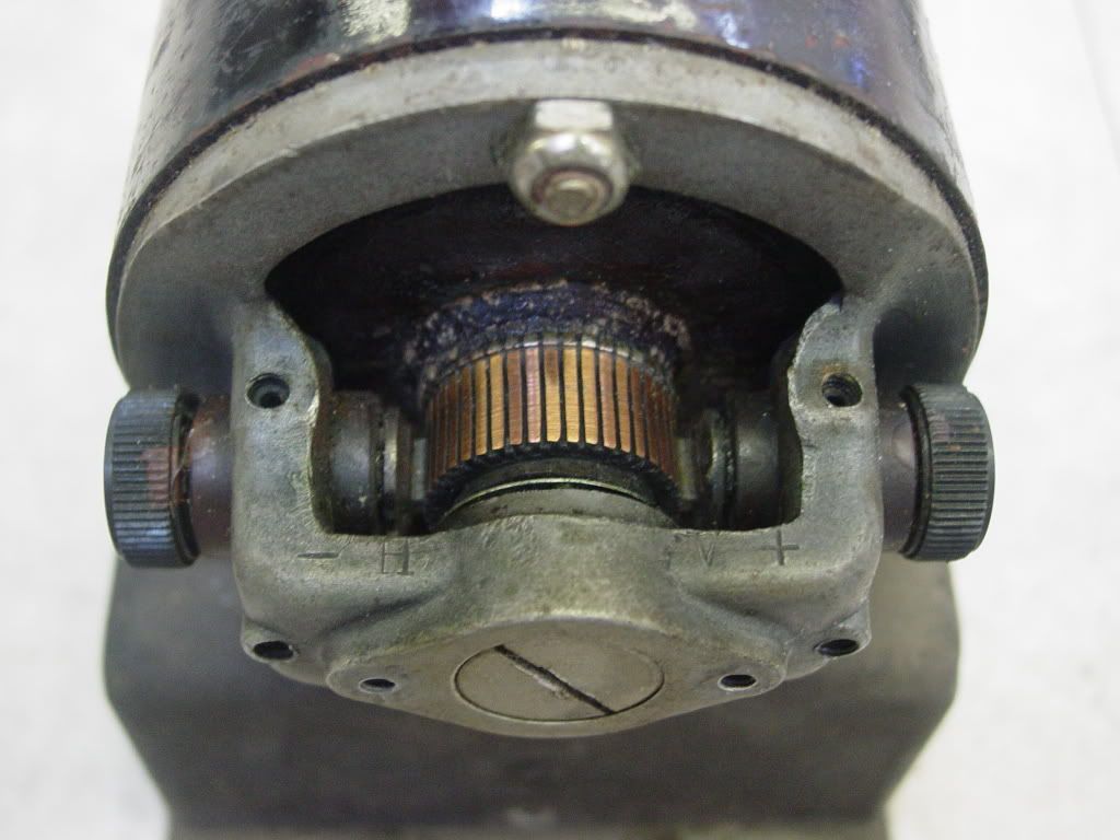
So now, in order to understand it, you must consider they are Electromagnetically Exchanging Flux and Electric charges Dynamically between them, therefore releasing energy from inside their center cores outwards...and as a matter of fact I am "replacing them at every degree of rotation", not only from closed Q1 (and I made a small error and got also "S1"in description...but I meant Switch 1 =Q1...) but also from the Mechanical Commutator switching them...
This I know complicates things a little bit...However, the best approach that I have used, is to "PAUSE" Mechanical Switching... analyze, then rotate... and analyze again...
So here goes my explanation...
You must "see" that two Inductors are getting energized "from inside out" also through a "Secondary Circuit" not "visible" in 2D Diagrams...a mechanical one.
Q1 closed, L1 charges, increase current (nanosecond pause here)
C1 (if the analysis refers to starting from Zero, it does nothing on first Pulse), if circuit was On, previously, then it backs Up L2 Charge, either obtained by rotation/replacement of Coils, or by C1 being charged at previous Off stage, or both simultaneously depending on alignment of Pulses versus Comm switching speed / note that Q2 is closed, and has an intrinsic diode or additional ones to protect the Oscillator negative switching side not allowing Positive charges...but ONLY a Negative charge to get through MOSFET...C1 is swinging left negative, since Q1 circuit being closed, is charging that leg negatively ...
reaching L2 and charging it or creating a resonance with L2, since if you look at it they are NOW in Parallel connection.
Regards
UFO
Originally posted by rosehillworks
View Post
Hello Rosehillworks,
Your Arrow is way more detailed than mine...
 ...it runs perfectly through circuit lines...mine are a bit "free style"...lol, since I wanted to show the currents through Coil L2
Let me explain, since I know how you are analyzing it...and SEPIC's behavior is not simple as normally operating...
I know you are looking at the diagram as two static Inductors on top of a Circuit Board...However, here, I have put them to work...to "sweat" to "earn their bread"...
 ...they were too lazy in their Air Conditioning rooms, just seating there pretty...
So now, in order to understand it, you must consider they are Electromagnetically Exchanging Flux and Electric charges Dynamically between them, therefore releasing energy from inside their center cores outwards...and as a matter of fact I am "replacing them at every degree of rotation", not only from closed Q1 (and I made a small error and got also "S1"in description...but I meant Switch 1 =Q1...) but also from the Mechanical Commutator switching them...
This I know complicates things a little bit...However, the best approach that I have used, is to "PAUSE" Mechanical Switching... analyze, then rotate... and analyze again...
So here goes my explanation...
You must "see" that two Inductors are getting energized "from inside out" also through a "Secondary Circuit" not "visible" in 2D Diagrams...a mechanical one.
Q1 closed, L1 charges, increase current (nanosecond pause here)
C1 (if the analysis refers to starting from Zero, it does nothing on first Pulse), if circuit was On, previously, then it backs Up L2 Charge, either obtained by rotation/replacement of Coils, or by C1 being charged at previous Off stage, or both simultaneously depending on alignment of Pulses versus Comm switching speed / note that Q2 is closed, and has an intrinsic diode or additional ones to protect the Oscillator negative switching side not allowing Positive charges...but ONLY a Negative charge to get through MOSFET...C1 is swinging left negative, since Q1 circuit being closed, is charging that leg negatively ...
reaching L2 and charging it or creating a resonance with L2, since if you look at it they are NOW in Parallel connection.
Regards
UFO
 If anything....
 [/IMG]
 [/IMG]
 [/IMG]
Comment