Announcement

Collapse
No announcement yet.

My Asymmetric Electrodynamic Machines

Collapse
X
 
  • Filter
  • Time
  • Show
Clear All
new posts

  • Repaired P27-P28...Epoxy Coated now...

    Hello to All,

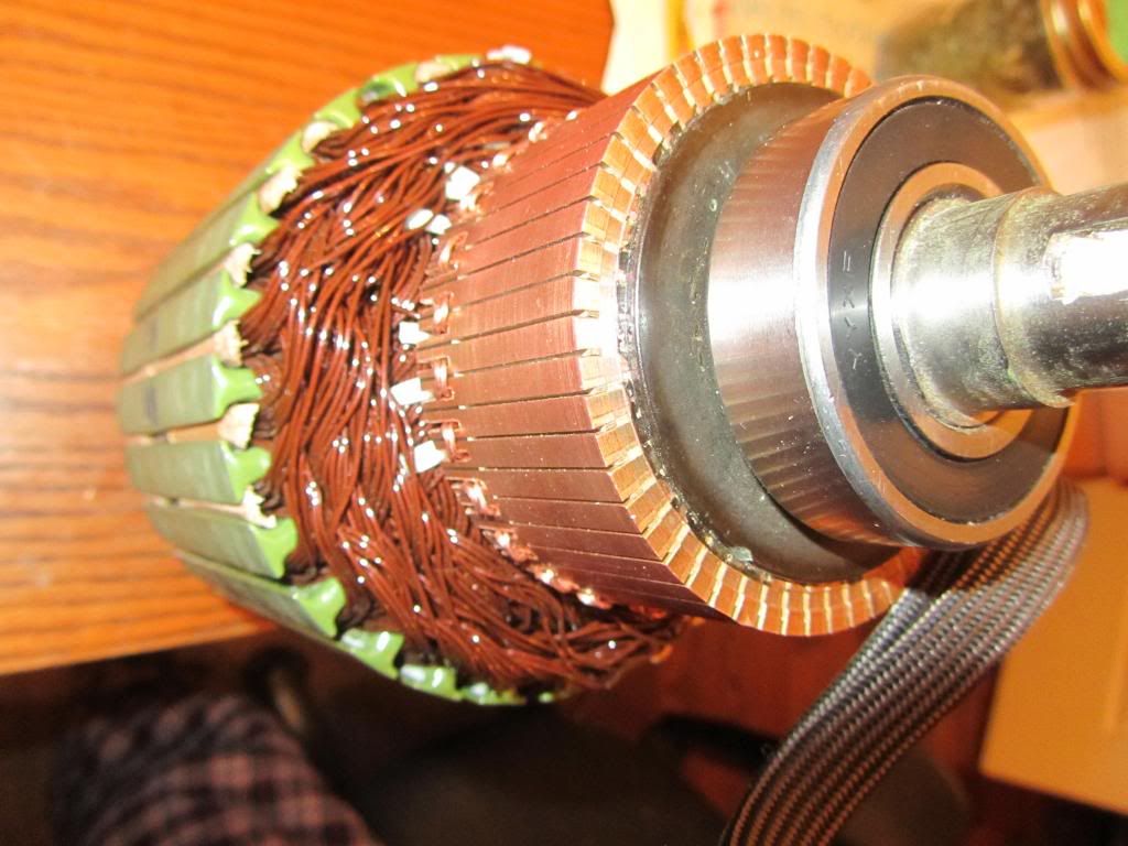
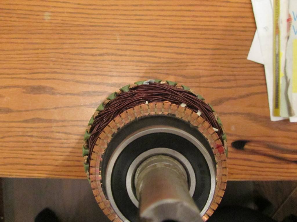
    Here is Rotor after repaired two broken windings...P27 and P28...
    And now all coils are Epoxied Coated...no more accidents, "no más"...
    Note how I masked Commutators and core...still it leaked through...but great, because it got into the hedges slots...so now they are secure.

    [IMG][/IMG]

    [IMG][/IMG]

    I used EPO230 made by Elantas...nice and rigid coat...but expensiveee!!...$65.00 a Pound...Class F will hold up to 155ºC=311ºF...Coils will never get there...

    Now the "Space Ball" is a Solid One...

    Have to take another weight measurement...see how much fatter it got..


    Regards to all


    Ufopolitics
    Last edited by Ufopolitics; 01-08-2013, 08:44 PM.
    Principles for the Development of a Complete Mind: Study the science of art. Study the art of science. Develop your senses- especially learn how to see. Realize that everything connects to everything else.― Leonardo da Vinci

    Comment


    • Of Course...is more work!

      Originally posted by machinealive View Post
      Hello everyone,

      Well, UFO, I've got the generator wound. That was alot more work then the motor, at least in my opinion. 7 turns of 19.5 ga. I would not try 8 turns .

      It weighs 8.765 kg. I'll post some pics tonight or tomorrow.

      Also got some steel bearings to replace imperials. Now I just gotta wait for stators, and it's go time.

      Machine


      Hello Machine,

      Grreat!...yes I know...Generator is much more work...hope it works now...

      I ordered just the small front Shaft from Mecc Alte...they want for front plate $115.00...and $16.00 for bearing...so, sorry, but nope...just shaft.

      I sent My Plate to be rectified by a real Lathe Monkey...I am not...

      So it should work just fine now...

      I also ordered for him to secure the Universal Joints by three screws...no more play...as also made them exchangeable to be 3/4 to 3/4 whenever I hook two Imperial Machines together...

      Told You am gonna be testing on 48V System now...reaching 10,000 RPM's...
      I would now Torque then...

      Take a look at the Quad Driver I have displayed...You could build it...


      Regards


      Ufopolitics
      Principles for the Development of a Complete Mind: Study the science of art. Study the art of science. Develop your senses- especially learn how to see. Realize that everything connects to everything else.― Leonardo da Vinci

      Comment


      • Originally posted by Donald Haas View Post
        !0 pole rotor, not epoxy dipped but has paper sleeves and plastic inserts on ends.

        When working to get the commutater free I tried hard blows with a soft heavy mallet to try and get the rotor to move on the shaft but it would not move.

        The shaft is 7.5in x 5/16, rotor is 1.5in long, 1 11/16 D, Case is 4 in long, 2.5 in D.

        The end cap with brushes come out easily because of through the case bolts, original bolts are 10-32, 4in.(3/16in) I found 10-24 threaded rod to extend.

        The original wire is .019inD, 24.5AWG (?)

        What would be best size to wind 10 pole asym?
        I have #28AWG, think that #25 would be better If someone else does these motors I can give tips for removing the comm.

        The mags have tabs on both sides. Have yet to remove them for "welding".


        bro d
        I noticed that the segment lines of the comm fall in the middle of the rotor segments.

        Is this common?

        The pics of winding patterns show the comm segment lines in the rotor gaps.

        I can speculate that the brush locations will accomodate this "feature".

        Help with this please!
        bro d

        brodonh's Library | Photobucket

        Comment


        • segment lines and rotor gaps

          Hi All,

          I attempted to post with this same info but it didn't seem to get through.

          I apologize for any dupes.

          In the photo you will see that the segment l ines of the original rotor position line up with the middle of the rotor poles on this 1o pole rotor.

          The winding pics show the rotor segment lines falling in line with the rotor gaps.

          What is going on with this. Are the brushes located to accmodate this relationship or ............. I didn't work on this original comm but I have installed the other comm on the shaft.

          I'm sure that the comm hasn't moved because there are spines holding it and the one that was removed from the other shaft was a bear to get loose.

          Thanks for any expertise on this!

          bro d


          http://i1284.photobucket.com/albums/...h/IMAG0066.jpg

          Comment


          • Not Important...

            Originally posted by Donald Haas View Post
            Hi All,

            I attempted to post with this same info but it didn't seem to get through.

            I apologize for any dupes.

            In the photo you will see that the segment l ines of the original rotor position line up with the middle of the rotor poles on this 1o pole rotor.

            The winding pics show the rotor segment lines falling in line with the rotor gaps.

            What is going on with this. Are the brushes located to accmodate this relationship or ............. I didn't work on this original comm but I have installed the other comm on the shaft.

            I'm sure that the comm hasn't moved because there are spines holding it and the one that was removed from the other shaft was a bear to get loose.

            Thanks for any expertise on this!

            bro d


            http://i1284.photobucket.com/albums/...h/IMAG0066.jpg

            Hello Donald,


            That is NOT Important as long as You reproduce EXACTLY SAME Position to the second Commutator...And I can NOT see it well...so can NOT tell you If it is fine like that or not.

            At time to wind make sure you use the best side element in commutator related to Diagram...that is all...Then later on you could adjust timing by moving both brush casing.


            Regards
            Principles for the Development of a Complete Mind: Study the science of art. Study the art of science. Develop your senses- especially learn how to see. Realize that everything connects to everything else.― Leonardo da Vinci

            Comment


            • Originally posted by Ufopolitics View Post
              Hello Donald,


              That is NOT Important as long as You reproduce EXACTLY SAME Position to the second Commutator...And I can NOT see it well...so can NOT tell you If it is fine like that or not.

              At time to wind make sure you use the best side element in commutator related to Diagram...that is all...Then later on you could adjust timing by moving both brush casing.


              Regards

              Thankyou UFO,

              I'm very curious how your 4 phase setup does torque wise.

              I did a symetrical 3 phase setup with 3 pairs of coils and was switching 900vdc (150 watts) with 3 banks of mosfets using optos and a timing wheel on the shaft.
              It worked but naturally lost torque relative to single phase switching of all coils three times per rev rather than switching each pair once per rev.

              Go for it!

              Thanks again for taking time for us late bloomers. LOL

              bro d

              Comment


              • RS motor problem

                Some input on my Radio shack motor project is sorely needed. Anyone jump-in, greatly appreciated!

                I just combined two bodies trying to make a more powerful motor since it was the same amount of labor. I originally thought that the bushings were too tight on the pieced together shaft and that it wasn't true and the motor must be binding. It did not turn very freely. I tore it down and replaced the 2-pieced shaft.

                Motor just gets hot. No hum. I have a nominal resistance of 3.5-4 ohms per coil.

                You can see the plastic poles in the body holes which indicate my brush placement. I think it is in accordance with neutral timing on this diagram:
                Winding Diagram 5-pole photo by sampojo | Photobucket

                Hooked up to a power supply it got up to over 100 degF, hot to the touch, drawing 2.5A.


                Lets look at magnet placement:
                south poles lined up photo by sampojo | Photobucket
                The light pink denotes South pole, and you can see the magnets are abutted in "series", N to S.


                So lets look at windings. Here is a blow-up of the 5-pole winding:
                RS 5-pole Blow-up photo by sampojo | Photobucket

                Looking at my last winding, indicated by the bright red arrows, it start at the front commutator at the 240 position(blue arrow), goes under the shaft to the right half coil and is wound CCW(viewing coil from the "bottom"), shown by the red oval, transitions to the left half, and now looking at the coil from the "top" was wound CW(blue oval), maintaining the "winding in the same direction".

                Last wound coil annotated photo by sampojo | Photobucket

                What did I miss?

                TIA

                Joe
                Attached Files
                Last edited by sampojo; 01-09-2013, 05:51 AM. Reason: added pic
                Up, Up and Away

                Comment


                • Hi Sampojo

                  Is the motor running, or is it getting hot while static? Did you use 1 pair of magnets or 2 pairs?

                  It looks like the brush position is correct.

                  It may be worth taking the rotor out and with some resistance inline connect to your power supply each commutator pair and then check with a compass needle that you are getting a N and S pole from the respective rotor poles, so check all 5 segments.

                  Regards

                  John
                  Last edited by john_g; 01-09-2013, 08:58 AM.

                  Comment


                  • Where do you guys stand now that six months have past ?

                    Amazing thread ! Great co-operation

                    Have any of the replicators had any encouraging results yet ?


                    All the best.

                    Comment


                    • UFO, JohnStone,

                      Instead of FETs you may want to consider IGBTs also. Here's one that's rated to 420A & 1,200v. This should work with the LM555 + 2 transistor driver. They're quite pricey.

                      http://docs-asia.electrocomponents.c...6b80aee96d.pdf

                      Lester444

                      Comment


                      • hi John,
                        Originally posted by john_g View Post
                        Is the motor running, or is it getting hot while static? Did you use 1 pair of magnets or 2 pairs?
                        getting hot STATIC. Its dead as a doornail. 2 pairs

                        Originally posted by john_g View Post
                        It may be worth taking the rotor out and with some resistance inline connect to your power supply each commutator pair and then check with a compass needle that you are getting a N and S pole from the respective rotor poles, so check all 5 segments.
                        OK, but everthing is relative right? It doesn't matter which one is north or south, just one of each?

                        Thanks

                        Joe
                        Up, Up and Away

                        Comment


                        • here are a few pics of generator


                          Comment


                          • Looks good!

                            Originally posted by machinealive View Post
                            here are a few pics of generator


                            Hey Machine,


                            Looking good!
                            Now, is it the picture or it seems wires are a bit loose at top?
                            They look kind of "curly"...
                            Are you really pulling them as you turn them?
                            Anyways, it could be solved by adding some epoxy on top, once you take it for a test drive...and they will be fine.


                            Regards friend, you are ahead of me here...already on Generator!


                            Ufopolitics
                            Principles for the Development of a Complete Mind: Study the science of art. Study the art of science. Develop your senses- especially learn how to see. Realize that everything connects to everything else.― Leonardo da Vinci

                            Comment


                            • Make a Test...

                              Originally posted by sampojo View Post
                              Some input on my Radio shack motor project is sorely needed. Anyone jump-in, greatly appreciated!

                              I just combined two bodies trying to make a more powerful motor since it was the same amount of labor. I originally thought that the bushings were too tight on the pieced together shaft and that it wasn't true and the motor must be binding. It did not turn very freely. I tore it down and replaced the 2-pieced shaft.

                              Motor just gets hot. No hum. I have a nominal resistance of 3.5-4 ohms per coil.

                              You can see the plastic poles in the body holes which indicate my brush placement. I think it is in accordance with neutral timing on this diagram:
                              Winding Diagram 5-pole photo by sampojo | Photobucket

                              Hooked up to a power supply it got up to over 100 degF, hot to the touch, drawing 2.5A.


                              Lets look at magnet placement:
                              south poles lined up photo by sampojo | Photobucket
                              The light pink denotes South pole, and you can see the magnets are abutted in "series", N to S.


                              So lets look at windings. Here is a blow-up of the 5-pole winding:
                              RS 5-pole Blow-up photo by sampojo | Photobucket

                              Looking at my last winding, indicated by the bright red arrows, it start at the front commutator at the 240 position(blue arrow), goes under the shaft to the right half coil and is wound CCW(viewing coil from the "bottom"), shown by the red oval, transitions to the left half, and now looking at the coil from the "top" was wound CW(blue oval), maintaining the "winding in the same direction".

                              Last wound coil annotated photo by sampojo | Photobucket

                              What did I miss?

                              TIA

                              Joe


                              Hello Sampojo,

                              Ok, make a test on Rotor...

                              Use a couple of 1.5 volts batteries...in series so it would be 3.0V...
                              Test first P1, by feeding from top-bottom connecting terminals...and use your compass to check you are getting North-South where they are supposed to be...
                              Do that with the rest...P2, P3, P4 and last P5...
                              Mark them as you go ...and make sure you DO NOT TURN the rotor while doing tests, so always same positive side...

                              You should have problems there...in the Pairs.
                              Motor is locking up...and no run...

                              Second tests:

                              Test for Ground leak on each with continuity meter...one element and ground...on all five.


                              Let me know...

                              Regards


                              Ufopolitics
                              Principles for the Development of a Complete Mind: Study the science of art. Study the art of science. Develop your senses- especially learn how to see. Realize that everything connects to everything else.― Leonardo da Vinci

                              Comment


                              • Found a Nice Breed...

                                Hello to all,

                                I found this nice MOSFET...they are used on an electric Bike I have...a 72 Volt, 80 Amps...gets 65 MPH...

                                The only problem I have seen, and the cause of failure ...is poor heat sinking...they will fry...if not well ventilated and cool...they are 330 Watts each.

                                http://www.irf.com/product-info/data...a/irfs4310.pdf

                                Below is a Picture of the MOSFET Failure, note the skinny and thin plate they used for Heat Sink...and that is not the Controller...but in the BMS side where MOSFET's disburse the Current from Charger to Batteries (Blue-Green Wires) and from Batteries to Controller Feed(Red-Black Wires)

                                [IMG][/IMG]

                                The Controller is a 120º(Three Phase) 80 Amps 72 Volts...for a Brushless Motor mounted on the rear wheel hub.

                                Pulsed Current they could hold up to 500 Amps...and 100 Volts
                                150A Continuous feed...

                                Excellent MOSFET!


                                Regards to all
                                Last edited by Ufopolitics; 01-09-2013, 05:20 PM. Reason: Add Picture
                                Principles for the Development of a Complete Mind: Study the science of art. Study the art of science. Develop your senses- especially learn how to see. Realize that everything connects to everything else.― Leonardo da Vinci

                                Comment

                                Working...
                                X