Announcement

Collapse
No announcement yet.

My Asymmetric Electrodynamic Machines

Collapse
X
 
  • Filter
  • Time
  • Show
Clear All
new posts

  • Originally posted by machinealive View Post
    Hey UFO
    I'm done tinkering. I have to use light switches but will have this hooked up tonight or tomorrow and run it. Patience man . I have found diodes that will do 20amps and 30 amps. I thought I was going to need much bigger ones, so thats good. I was thinking a bleeder might be bad in this app.
    In your new vid, the motor is doing about 3500 rpm, which is close to mine. I thought in your original test it was doing 7000 rpm. If you were not pulsing it why was is going so fast. I thought it was 36volts straight and thats what I was shooting for

    @cornboy. That really looks nice. I cant wait to see the finished motor.
    Hey Machine,

    Motor does 7000 RPM's IF, I hook ALL in Parallel, 40V at FULLY Charged Bank.

    And watch Video 1 better...with Turbo Boost it reaches over 5000 RPM's

    You should run a LOAD TEST on your Batteries...sometimes Batteries show full voltage but when you apply load they drop very low or even zero...and you just need one bad battery there to ruin your whole bank.

    I have one of those 100 AMP Load Testers, that by pressing momentary the load (a huge wire resistor hold by insulation), the needle will drop to either "good" or "bad"...Now there are Electronic ones...but more $$


    Something like this...

    [IMG][/IMG]


    So, going back to Your Generator Hook up...just get Pure Generator total output...when turning it with Motor connected externally with the Diodes. However there are many tests you could do there...You have your hands full...

    Regards


    Ufopolitics
    Principles for the Development of a Complete Mind: Study the science of art. Study the art of science. Develop your senses- especially learn how to see. Realize that everything connects to everything else.― Leonardo da Vinci

    Comment


    • Precision on smaller motors a pain

      Originally posted by Lester444 View Post

      @Sampojo,

      Rotor diameter is 40mm, 12-poles. The hole for the shaft was actually 6.4mm (very loose fit) so I had to wrap a 0.2mm shim (medical x-ray film) on the 6.0mm shaft to make it a snug fit. Then super glue into the gap holds it in place. Same thing done with the commutators. The bearings were an exact fit on the 6mm drill rod.
      A SNUG fit would be the best I imagine, so that you can be sure there is no rotation of shaft on the inner seat? But exact is not bad, I assume. Just a smidge of epoxe would take care of that. I am tempted in these fit situations to put a dimple on the shaft to get the snug fit but I think that would throw it out of true. I want to replace my RS housings and bushings with bearings. my shaft I am using is .093" while bearings I am ordering are 3/32". The .00075 ensures a loose fit. but so be it, still better than bushings. Gotta get lucky and find some 3/32 wire somewhere.

      My soldered elongated body is too short, binds the rotor, Put a little glue on the magnets, body out of round, and there is way too much rubbing going on. So I might like to house the motor in a new tube.

      ALL:

      Does it matter what material you may use for the motor housing?

      Heavier Steel tube, what would it do to the mag fields?

      PVC plastic? heating issue? CPVC?

      Copper pipe (if I can get the right dia.) will not respond to magnetism?
      Up, Up and Away

      Comment


      • Materials for Frame...

        Originally posted by sampojo View Post
        A SNUG fit would be the best I imagine, so that you can be sure there is no rotation of shaft on the inner seat? But exact is not bad, I assume. Just a smidge of epoxe would take care of that. I am tempted in these fit situations to put a dimple on the shaft to get the snug fit but I think that would throw it out of true. I want to replace my RS housings and bushings with bearings. my shaft I am using is .093" while bearings I am ordering are 3/32". The .00075 ensures a loose fit. but so be it, still better than bushings. Gotta get lucky and find some 3/32 wire somewhere.

        My soldered elongated body is too short, binds the rotor, Put a little glue on the magnets, body out of round, and there is way too much rubbing going on. So I might like to house the motor in a new tube.

        ALL:

        Does it matter what material you may use for the motor housing?

        Heavier Steel tube, what would it do to the mag fields?

        PVC plastic? heating issue? CPVC?

        Copper pipe (if I can get the right dia.) will not respond to magnetism?

        Hello Sampojo,

        A heavy Steel Tube...regular carbon steel too thick will weaken the magnetic field that opposes to tube...and those are the ones you want stronger...

        Aluminum will be perfect there. As Copper

        Any Hard Plastic, Fiberglass, Kevlar, Carbon Fiber...etc...not PVC, PVC is too soft.

        Or a fine steel tube like motor had originally...

        In all events, make sure you open holes for brushes commutator ventilation...


        Regards


        Ufopolitics
        Principles for the Development of a Complete Mind: Study the science of art. Study the art of science. Develop your senses- especially learn how to see. Realize that everything connects to everything else.― Leonardo da Vinci

        Comment


        • Running from a power supply

          All,

          I was running my RS briefly on a PC converted power supply and it went dead. It should have been able to do about 10a. I don't think it had current limiting. I hooked it up to my 12volt car battery charger, and the current limiter I guess kicked it off. The charger icame back to life. The motor has a lot of friction issues. When a coil is just hooked up straight on 12v no rotation, i.e. testing one coil, it would draw 2.5a@~12v, ~4ohm resistance per coil.

          Is there some surge in current draw on startup? Why would it be greater than the nominal 2.5a?

          AH HA. I bet the brushes will allow a voltage spike by contacting 2 coils at once momentarily, getting a current spike, cutting resistance down to 2ohms. Still just 6a. bet that power supply cant take that sort of current fluctuation?
          Up, Up and Away

          Comment


          • Communication.

            Hello UFO, and all, i have oppened a youtube account so i can communicate with you all on the MAG3-SB, if i have any problems i'll ask if you dont mind.

            I feel this will be best form of showing build progress, only thing is you have to put up with my voice, who knows i might even show my ugly mug.

            One question for all, is the green epoxy, on quality rotors, available in small quantities? and what is it called?

            Thanks Cornboy.

            Comment


            • Vortex.

              Originally posted by JohnStone View Post
              Me too. But I feel it is much more to it:

              We know two types of resonance:
              • LC resonance is what we imagine if we talk of resonance.
              • There is a resonance available regarding wire length. There is a patent out there pondering on what happens if we build coils haveing both resonances aligned to the very same frequency. (gigantic coils!)

              The latter resonance is never regarded in usual electromagnetic machines. If we talk of heavy pulsing our machines we - of course - make use of resonance ringing in any respect. As long we do not know HOW exactly assymmetric motors operate (or magnetic transfer and reaction in all respect and in general) it is wise to make windings same length if possible.

              Our notion that current in a coil produces magnetism and this magnetism transfers energy to a secondary winding is extremely superficial. There are simplified thinking models regarding this matter and this seems to be a natural law. It is as if we say: if you are cold you get a cold - simplified - yes- it is true for most cases. But what about IF NOT? Detect another "law of nature" not known before.

              Research deals with facts NOT known well and therefore it is wise to regard some minute details up the the time when we know they are not relevant - but if they are important we grow them up. But before we do not know where those parametrs live.

              Another example: There is a patent out there talking about wires being coated with semiconducting layers. Electrons are told to travel supraluminal in those layers being accelerated by an obscure energy (not by input power). If they dive back into the wire they forward their kinetic energy to other electrons living there and thus the output is OU. (simply said: OU transformer by using coated wire) Copper oxide is semiconducting! Now imagine a poor boy tinkering with some oxidized wires from scrap and gets OU. We buy new shining wires from the shop and try same setup - nada. What do we think? Do we regard this poor boy to be a inventor?

              We are blessed to have UFO as instructor but please regard this thread to be possibly a place where we may discover much more than UFO can teach just now.
              You can teach known matters only!!!!
              JohnS


              Hello guy's, i think i may have answered my own question, UFO stated that with the spirel of life winding, that the first inner winding on the rotor was the weakest leading to the last outside winding being the strongest field, and that it produces the hammering effect every 360 revolution.

              This makes complete sense to me being a BIO-DYNAMIC farmer who deals with VORTEX forces in preparing preps for use on soil.

              You won't get any more assymetric than the spiral of life.

              SOOO, answer is same number of turns.


              Warm regards Cornboy.

              Comment


              • Link.

                Originally posted by Cornboy 555 View Post
                Hello UFO, and all, i have oppened a youtube account so i can communicate with you all on the MAG3-SB, if i have any problems i'll ask if you dont mind.

                I feel this will be best form of showing build progress, only thing is you have to put up with my voice, who knows i might even show my ugly mug.

                One question for all, is the green epoxy, on quality rotors, available in small quantities? and what is it called?

                Thanks Cornboy.
                Hello all, have uploaded short vid to youtube, just to try it, but can't work out how to post link here.

                Much appreciate some help on this.

                Thanks cornboy.

                Comment


                • @ cornboy, copy link from yt and paste it in add link in energetic forum reply.

                  OK UFO, finished getting everything put together for tonight, I need to get to the store for a few more connectors, etc. Worked fantastic, same RPM and volts as you were getting. I have to get the high amps DC meter, so all I could do is Vin and V across caps, and RPM.

                  Anyway, I'm posting link but it may take hrs to upload. I have to crash, almost 4 am.

                  imperial turbo run - YouTube

                  I will get the gen spinning this weekend, and order some meters. Your wiring for diodes and coils was sooo cleaver Ufo, thanks ufo, excellent.

                  Machine

                  Comment


                  • 00126 - YouTube

                    Don't quite know how i did it, will have to retrace steps, What a mission, every lamination had a flat file run over it first to remove any possible com tamination.

                    I will take UFO's advice, and put small groove down lams and stich weld with mig.

                    Will keep you posted.

                    Regards Cornboy.
                    Last edited by Cornboy 555; 01-19-2013, 09:34 AM.

                    Comment


                    • Nice Cornboy!

                      Originally posted by Cornboy 555 View Post
                      00126 - YouTube

                      Don't quite know how i did it, will have to retrace steps, What a mission, every lamination had a flat file run over it first to remove any possible com tamination.

                      I will take UFO's advice, and put small groove down lams and stich weld with mig.

                      Will keep you posted.

                      Regards Cornboy.

                      Hello Cornboy,


                      Video loaded great!...too short though!!

                      Will have to give you an Intensive Course on You Tube, Photobucket and Hollywood style filming...

                      That rotor looks so good!!


                      I will take UFO's advice, and put small groove down lams and stich weld with mig.
                      Cornboy, I meant to do that, to Groove-Weld on Stator Lamination's ONLY...but NOT on Rotor!!

                      You do not have much room on Rotor Poles to do that...and MIG Welding there could blow one of small "T" Shape poles!!

                      In Stators you do that groove in the BACK of Stators...NEVER in the front!...For Front pressing (ONLY IF YOU NEED TO)...You could use a heavy copper flat piece make a grove and press it like a "C" Clamp.

                      But I have noticed You have holes at rotor and stators...so bolting them together (like I notice you did) will be just perfect...Use Brass or Copper Bolts if available..


                      Regards


                      Ufopolitics
                      Principles for the Development of a Complete Mind: Study the science of art. Study the art of science. Develop your senses- especially learn how to see. Realize that everything connects to everything else.― Leonardo da Vinci

                      Comment


                      • Hey Machine...

                        Originally posted by machinealive View Post
                        @ cornboy, copy link from yt and paste it in add link in energetic forum reply.

                        OK UFO, finished getting everything put together for tonight, I need to get to the store for a few more connectors, etc. Worked fantastic, same RPM and volts as you were getting. I have to get the high amps DC meter, so all I could do is Vin and V across caps, and RPM.

                        Anyway, I'm posting link but it may take hrs to upload. I have to crash, almost 4 am.

                        imperial turbo run - YouTube

                        I will get the gen spinning this weekend, and order some meters. Your wiring for diodes and coils was sooo cleaver Ufo, thanks ufo, excellent.

                        Machine

                        Hey Machine,

                        That's great!!...whenever you wake up...take a look at video...still loading...something must be wrong there...it is now around 9:00 AM...
                        On DC Clamps. I've got a Klein, it was $139.00,it is True RMS (which is True Reading, what we want here)...got it at Home Depot.

                        Today I am gonna try Caps in series...to see if I could get the "delay effect" longer this way....and here is where our "Light" will be Machine...delaying this Turbo Boost by filling Caps and obtaining Higher/Top RPM's at lower Amps draw (in our future Oscillator this Caps will be at end between Drain and Positive Source.

                        And yes...this circuit is clever...In order to really understand it, we must follow the constant switching polarity coils, as they also transfer reversed charges for Milli seconds to next coils, diodes regulate/direct flow. We could play with this circuit much, much more...

                        You should not be getting high sparking with this circuit right?

                        Regards my friend


                        Ufopolitics
                        Principles for the Development of a Complete Mind: Study the science of art. Study the art of science. Develop your senses- especially learn how to see. Realize that everything connects to everything else.― Leonardo da Vinci

                        Comment


                        • Originally posted by Lester444 View Post
                          Hello John,

                          After reading the links you posted I understood what you were trying to say about the rotor bisector. Thanks for that!

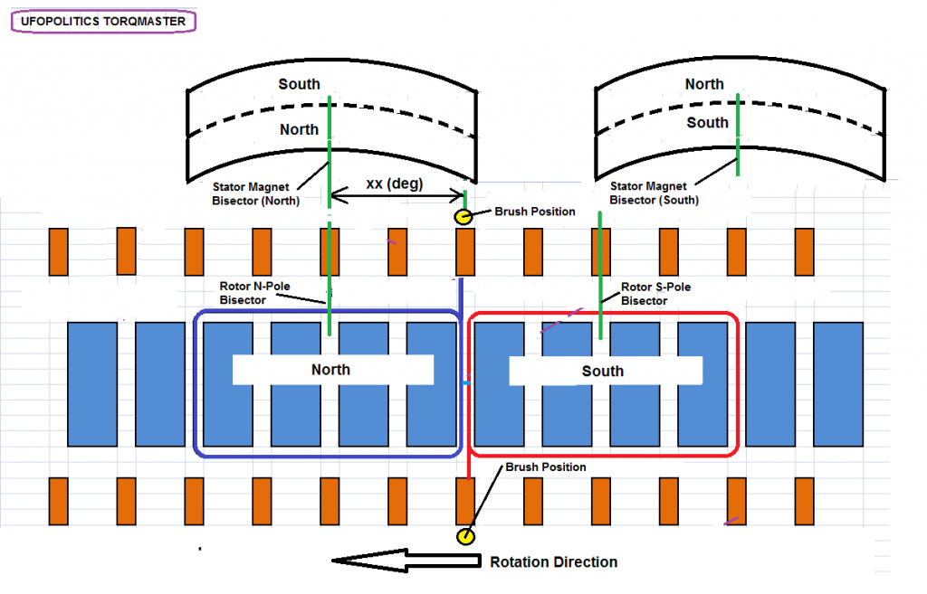
                          I tried to edit the drawing as you requested but it became too cluttered so I felt that a second page will convey the idea better. I have drawn the timing relationships here in such a way that I can understand it, but have left out some information simply because it is still unclear to me at this time. Please feel free to edit as you see fit (Paint SW), or, if you have a better SW for drawing then please feel free to use it and post your drawing here.

                          Info still needed:
                          1. Battery polarity at the upper brush
                          2. Battery polarity at the lower brush
                          3. Brush position relative to stator magnet N-pole bisector: xx (deg)
                          4. Is rotation direction correct the way I drew it?
                          5. Anything else you might want to add

                          Lester

                          YES! That's perfect!
                          • Lower brush is battery plus -> right hand rule thump showing to bottom so S is up like displayed.
                          • Current continues to flow in blue wire -> right hand rule thumb showing up so there N is up. -> upper brush is battery minus.


                          I added polarity, current flow and a line showing the wire changing S pole to N pole.

                          Regaring brushes: depending on the construction of your motor the brushes might be in line with magnets or they might be positioned aligned with the gap between magnets.
                          Facing this fact you can not draw a diagram of common correctness. You need to know on where the brushes are monted. Bisectors north being aligned you need to connect the coil to that segment being center of brush. MArk that to be + or -
                          I wired my coils conformign UFOs diagram and did not notice that my brushes were 90 degree rotated. So I had to rewire the coils before the motor run well.
                          Last edited by JohnStone; 01-19-2013, 03:12 PM.
                          Experts spend hours a day in order to question their doing while others stopped thinking feeling they were professionals.

                          Comment


                          • Hello John,

                            Originally posted by JohnStone View Post
                            YES! That's perfect!
                            • Lower brush is battery plus -> right hand rule thump showing to bottom so S is up like displayed.
                            • Current continues to flow in blue wire -> right hand rule thumb showing up so there N is up. -> upper brush is battery minus.


                            I added polarity, current flow and a line showing the wire changing S pole to N pole.

                            Regaring brushes: depending on the construction of your motor the brushes might be in line with magnets or they might be positioned aligned with the gap between magnets.
                            Facing this fact you can not draw a diagram of common correctness. You need to know on where the brushes are monted. Bisectors north being aligned you need to connect the coil to that segment being center of brush. MArk that to be + or -
                            I wired my coils conformign UFOs diagram and did not notice that my brushes were 90 degree rotated. So I had to rewire the coils before the motor run well.

                            Hello John,

                            Lester was setting this diagram based on Starting to wind from center of wire (center between two Rotor Coils)...Then Lester was "seeing" both windings CCW...which is correct, BUT, I corrected the fact that it does matter from where you start winding, as you will see it from different points of view...however the final result is exactly the same.

                            Here is My Diagram related to that:

                            [IMG][/IMG]

                            So North Pole (Projecting toward Screen, Us) is CCW IF LOOKED from center of wire, BUT Feeding Positive from TOP BRUSH, not from bottom like you have it

                            I always recommend to keep Positive Brush UP, at any time of winding, and as a steady guide will better if our Main Connecting Shaft side, is the commutator side we use for positive reference.

                            My Right Hand Guide that I have explained on my First Winding Tutorial:

                            Asymmetrical Winding Part 1 - YouTube

                            shows it very clear.

                            @Lester: Whenever you display Stators or Rotors Magnetic Poles Diagrams, please, DO NOT show the "other side magnetic poles" that are NOT Interacting in the rotation, as all it brings is pure confusion...If You notice, in ALL My Diagrams of Stators...I only show either South or North...

                            We all know that a Monopole Magnet does not exist so far...or, if it does...we have not found it yet...


                            Kind regards


                            Ufopolitics
                            Last edited by Ufopolitics; 01-19-2013, 03:59 PM.
                            Principles for the Development of a Complete Mind: Study the science of art. Study the art of science. Develop your senses- especially learn how to see. Realize that everything connects to everything else.― Leonardo da Vinci

                            Comment


                            • OK Ufo, you are right.
                              Your drawing is clear and modifying the other one will result in same what you have drawn.
                              In your drawing anybody can read that if we start winding with center of wire we need to turn CCW both sides.

                              Adding the notion that it will help considerably to wire the motor to end it is very helpful to imagine armature bisector N being aligned to stator bisector north.
                              With this alignenemnt in mind we need to find the corresponding commutator segment being aligned to the very real brush contacting it in that position.

                              BTW: If I apply the right hand rule to your drawing it seems to me that N and S are reversed. I might be wrong!
                              Last edited by JohnStone; 01-19-2013, 04:31 PM.
                              Experts spend hours a day in order to question their doing while others stopped thinking feeling they were professionals.

                              Comment


                              • hey UFO,

                                It still says it's only 75% done, I don't know why it is so slow uploading to yt. Sorry. In terms of sparking, no there was not alot until I hit turbo, but still not close to the original sparking. Yea, I had to draw that wiring diagram a few ways to get it. How long did it take you to come up with that one, you didn't write that up overnight, huh ? Your previous post for upper and lower comm, expanded flow was excellent, on that post where are the diodes 1a, 2a, 3a and 4a cathodes connecting, or are they open.
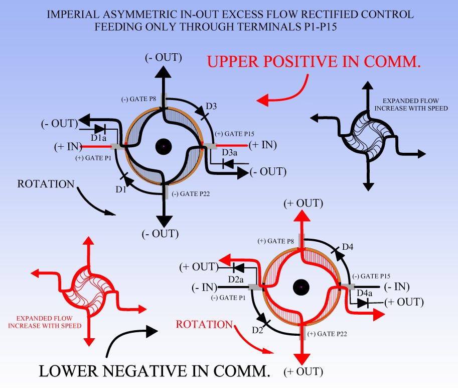


                                regards
                                Machine

                                Comment

                                Working...
                                X