Announcement

Collapse
No announcement yet.

My Asymmetric Electrodynamic Machines

Collapse
X
 
  • Filter
  • Time
  • Show
Clear All
new posts

  • Traction Motors...our Next Frontier?

    Hey Machine, Cornboy, Prochiro...and All those great hard working building guys out there...

    What about Traction Motors?

    [IMG][/IMG]

    Have You seen this Monsters?...We need Forklifts to lift them off their Pallets...

    Electric Motor Repair and Traction Motor Repair

    Take a look at those Commutators Brushes Arrangements...nice Uh?

    http://www.swigercoil.com/upload/new...pabilities.pdf

    Imagine this "Things" converted to Asymmetrical Tech?


    Will love to get my hands on one of this things...wouldn't you?


    I have been following this Motors for a while...they make them AC and DC...Room enough to set the Dual Commutators in One shaft end...


    Regards


    Ufopolitics
    Principles for the Development of a Complete Mind: Study the science of art. Study the art of science. Develop your senses- especially learn how to see. Realize that everything connects to everything else.― Leonardo da Vinci

    Comment


    • So many ideas, . . .

      UFO
      Looks like 2013 is going to be a Great year !!!

      Got introduced to your work via YouTube - Was much Impressed with all

      Started reading the my-motors-got-me-tap-into-radiant-energy thread from page 1 post 1 ( both good & bad ) to current date, then joined ( so we could see all the details )

      I have to say, don't know that I could have walked the same path & not given up. You have a gift and have freely shared it with the world.

      Now we are reading all the symmetric-versus-asymmetric-electromagnetic-systems thread and forming an attach plan !!!!

      No questions yet, still in absorb mode, just wanted to touch base and say Thank you, Thank you, Thank you
      - you have give me some new goals in life.

      We will post our replication as work progresses.
      now if I can just remember where the camera is . . . .

      Comment


      • Short Circuit Motors.

        Originally posted by Ufopolitics View Post
        Hey Machine, Cornboy, Prochiro...and All those great hard working building guys out there...

        What about Traction Motors?

        [IMG][/IMG]

        Have You seen this Monsters?...We need Forklifts to lift them off their Pallets...

        Electric Motor Repair and Traction Motor Repair

        Take a look at those Commutators Brushes Arrangements...nice Uh?

        http://www.swigercoil.com/upload/new...pabilities.pdf

        Imagine this "Things" converted to Asymmetrical Tech?


        Will love to get my hands on one of this things...wouldn't you?


        I have been following this Motors for a while...they make them AC and DC...Room enough to set the Dual Commutators in One shaft end...


        Regards


        Ufopolitics


        Hi UFO, most of these monsters have large single or double conductors, which you call short circuit motors, dont they?

        Is there a way to make them assymetric in the windings?

        They seem same design as modern EV DC Traction motors.

        Also did some research into armature coatings on mass produced rotors and found those products are powder epoxy's electrostatically applied, not for one off job's.

        Still looking for good product locally.

        Regards Cornboy.

        Comment


        • Cornboy
          Look, UFO is showing pictures of your monster and its friends. Well anyway, your the closest to them at this point although you would not need a tow motor to lift 48 pounds, But maybe you would after all the wire and comms are on. HeHeHe.
          Dana
          "Today's scientist have substituted mathematics for experiments and they wander off through equation after equation and eventually build a structure which has no relation to reality."
          Nikola Tesla

          Comment


          • Many Thanks and Welcome!!

            Originally posted by Hitby13kw View Post
            UFO
            Looks like 2013 is going to be a Great year !!!

            Got introduced to your work via YouTube - Was much Impressed with all

            Started reading the my-motors-got-me-tap-into-radiant-energy thread from page 1 post 1 ( both good & bad ) to current date, then joined ( so we could see all the details )

            I have to say, don't know that I could have walked the same path & not given up. You have a gift and have freely shared it with the world.

            Now we are reading all the symmetric-versus-asymmetric-electromagnetic-systems thread and forming an attach plan !!!!

            No questions yet, still in absorb mode, just wanted to touch base and say Thank you, Thank you, Thank you
            - you have give me some new goals in life.

            We will post our replication as work progresses.
            now if I can just remember where the camera is . . . .

            Hello and Welcome, Hitby13kw,

            Yes you would "hit" those 13 Kwatts...

            Thanks for all your kind words, as I am very proud I have inspired you into this!

            Regards and Enjoy the Show...There is a lot more to come...


            Ufopolitics
            Principles for the Development of a Complete Mind: Study the science of art. Study the art of science. Develop your senses- especially learn how to see. Realize that everything connects to everything else.― Leonardo da Vinci

            Comment


            • Hey Cornboy

              Originally posted by Cornboy 555 View Post
              Hi UFO, most of these monsters have large single or double conductors, which you call short circuit motors, dont they?
              Some do, some don't...and they have those "Pre Build Coils", already shaped like you see in the right upper picture (Guy Winding One)

              Now, look at the middle outer left Picture (Wound Finished Armature)...see the space between poles?

              Also in the bare armature...(center upper)...see space?

              [IMG][/IMG]


              And..."Short Circuit Motors"...are ALL the Symmetrical Motors we know off...that's how they are all called...they are in short circuit since you start that motor, my friend...get a continuity meter...and test ANY point in their armatures...will see the "short" there in all.

              Is there a way to make them assymetric in the windings?
              Absolutely and Positively YES!

              They seem same design as modern EV DC Traction motors.
              Nope...

              Also did some research into armature coatings on mass produced rotors and found those products are powder epoxy's electrostatically applied, not for one off job's.

              Still looking for good product locally.

              Regards Cornboy.
              Cornboy, there must be an Australian Motor Manufacturer my friend...and they will get you to that resin supplier-manufacturer...am sure of it.

              BUT, there is another way to Isolate Rotor without Resin...wanna know?

              How much money you have?...


              Ok, just have same laser guy who laser cut your rotor laminates...and get him a nice sheet of High Temperature Plastic, Mica...or Bakelite...a sheet...just to make Two same exact pattern Rotor 36 pole star...then you attach it at top and bottom...and then...You get that special paper they use on Motors...like a High Temperature Fiber Paper (have to search my friend on that)...normally they have a very shiny side and Matte other side...then you will have to cut straight strips (make a pattern for it) and bend them in a "V" Shape...they will go in between each poles gaps...so you just need 36 strips...and wind, wind wind...

              They use this method on many Motor manufacturers...I particularly like the Resin process better...but, I tell you...(have no idea if you have done it before) but I tell you...it is not a simple process to make it...because resin keeps dripping off and becoming much less at hard edges...so you have to keep moving whole rotor getting distributed very evenly, so, in order to prevent resin to run off ...or to accumulate more in one side than other...In typical Motor Manufacturing...they have a special "Gravity Rotor Rack"...or Vacuum Chambers, where armatures get mounted while spraying this resin...they move slow...in all spherical 360º...to prevent this accidents to occur...and resin takes a while to become "Jelly State"...


              Regards my friend


              Ufopolitics
              Last edited by Ufopolitics; 01-20-2013, 03:02 AM.
              Principles for the Development of a Complete Mind: Study the science of art. Study the art of science. Develop your senses- especially learn how to see. Realize that everything connects to everything else.― Leonardo da Vinci

              Comment


              • Hello all,

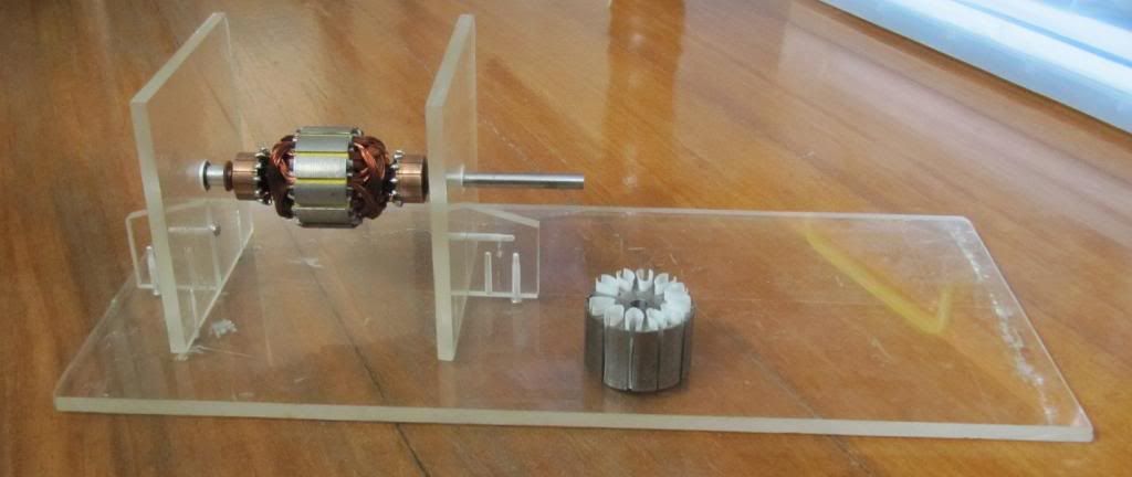
                Just a quick update to show you my progress. It's basically a test platform so I will be able to re-configure if needed. Will also be able to add reed switches or hall sensors for precise pulse placement and see its effects, if any. The rotor spins freely on 2x miniature ball bearings

                There's room at the other end for a load or a generator. Hoping to be able to loop it back for a self-runner, even with less than 2 watts OU. Just a small & cheap proof of concept before spending money on a bigger machine.


                @UFO,

                If you would be so kind to answer some questions:
                1. Would 4x magnets be better than 2x with this 12-pole rotor? Winding config is 12-pole TorqMaster.
                2. Should I go directly to 4x magnets or should I start with 2x? I will use curved ceramic magnets.

                I chose to go with this design because you said:
                This Design is better than the Star of David...more coils (12 Pairs/24 Coils) So, Pmazz...You got it right here...

                It is more "stable" and balanced in electromagnetic interactions...it should deliver excellent torque and also great speed...yes, both.
                Reference: http://www.energeticforum.com/renewa...chines-31.html

                Thank you.

                Lester

                Last edited by Lester444; 01-20-2013, 04:20 AM.

                Comment


                • S Word.

                  Originally posted by prochiro View Post
                  Cornboy
                  Look, UFO is showing pictures of your monster and its friends. Well anyway, your the closest to them at this point although you would not need a tow motor to lift 48 pounds, But maybe you would after all the wire and comms are on. HeHeHe.
                  Dana
                  Hey DANA, just finished assembling the third stator pack, they weigh 8 pounds each, so there is another 48 pound, OH OH, rotor pack is the same weight That's very, dare i say it, symetrical, there i just said the s Word.

                  Regards Cornboy.

                  Comment


                  • Maybe.

                    Originally posted by Ufopolitics View Post
                    Some do, some don't...and they have those "Pre Build Coils", already shaped like you see in the right upper picture (Guy Winding One)

                    Now, look at the middle outer left Picture (Wound Finished Armature)...see the space between poles?

                    Also in the bare armature...(center upper)...see space?

                    [IMG][/IMG]


                    And..."Short Circuit Motors"...are ALL the Symmetrical Motors we know off...that's how they are all called...they are in short circuit since you start that motor, my friend...get a continuity meter...and test ANY point in their armatures...will see the "short" there in all.


                    Absolutely and Positively YES!


                    Nope...


                    Cornboy, there must be an Australian Motor Manufacturer my friend...and they will get you to that resin supplier-manufacturer...am sure of it.

                    BUT, there is another way to Isolate Rotor without Resin...wanna know?

                    How much money you have?...


                    Ok, just have same laser guy who laser cut your rotor laminates...and get him a nice sheet of High Temperature Plastic, Mica...or Bakelite...a sheet...just to make Two same exact pattern Rotor 36 pole star...then you attach it at top and bottom...and then...You get that special paper they use on Motors...like a High Temperature Fiber Paper (have to search my friend on that)...normally they have a very shiny side and Matte other side...then you will have to cut straight strips (make a pattern for it) and bend them in a "V" Shape...they will go in between each poles gaps...so you just need 36 strips...and wind, wind wind...

                    They use this method on many Motor manufacturers...I particularly like the Resin process better...but, I tell you...(have no idea if you have done it before) but I tell you...it is not a simple process to make it...because resin keeps dripping off and becoming much less at hard edges...so you have to keep moving whole rotor getting distributed very evenly, so, in order to prevent resin to run off ...or to accumulate more in one side than other...In typical Motor Manufacturing...they have a special "Gravity Rotor Rack"...or Vacuum Chambers, where armatures get mounted while spraying this resin...they move slow...in all spherical 360º...to prevent this accidents to occur...and resin takes a while to become "Jelly State"...


                    Regards my friend


                    Ufopolitics


                    Thats Great UFO, only trouble is i don't have a train right at this point, i could possibly rustle up a truck or two though.

                    But, Wait, i do have a header with a 100hp diesel motor, and a 80hp tractor that need upgrading to electric Sooo we will see.


                    Regards Cornboy.

                    Comment


                    • my next step on the learning curve

                      Well I think my windings burnt up. shorts to the shaft, open circuits on opposite poles that should be 4 ohms. Might have pushed the commutator in too far and nicked some wires trying the rotor in it work in a body that was just 1/16" short. But I am satisfied that I can make an asymmetrical motor now, but need to improve my skills.

                      Here is the hardware I have pulled together for 3 projects.


                      My double rotor RS I made the body as long as I could, but still too short, so I have found that 1" ID copper pipe (shown) is a near perfect fit. I liked lester's idea of putting bearings on and those are on order. I think I will need to whack the shaft to broaden it so that I get a snug fit, to make up for a .00075 mismatch on my shaft material. I believe I can keep it true. The bearing OD will fit well in the motor end plates at 5/32". The red arrow shows the bushing popped out of the housing.

                      I want to build a couple more RS single rotors, one with the lower 28ga wire recommended. I want to drive the double rotor as a generator with the higher power single rotor I think that will result, to see what kind of miniature motor results I can get. I have an appliance that is not so good on batteries and I want to replace its motor with an 32ga RS version.

                      Stepping up a size, I have 4 10-pole car window motors and want to make 2 asym motors out of these, looking at using the P71 #2124 winding.

                      I have shaft replacement material and will order bearings. Gotta rotate the brushes 90dg, which will be tough since it is not round, which pushes toward the idea of housing replacement, just needing 1 3/4" ID pipe. Then I start thinking, I will have room and a couple extra magnets. Dont let them go to waste, so why not a 4-mag motor like Ufo's Bosch?

                      So I would use this winding for that.

                      But since it is a ten pole I use 2 poles per coil not 4.

                      Here is a few questions for UFO then.
                      1. So this motor must have a total of 8 BRUSHES ++-- motor and ++-- gens ?
                      2. For wiring, do you connect the input power motor + terminals together onto the power?
                      3. Are you and machine building an asym gen and if so, where approximately in the thead is the best place to start studying it?


                      I want to try to convert a salvaged induction motors to a generator to run off of the first 10-pole I build, the one I have is shown in the first pic, before I invest 600 in a Mecce Alte.

                      I have a question about what generator output (harvested CEMF) looks like on an O-scope. I am assuming it is similar to BEMF from any non-motor coil, which must be very spikey high voltage, ringing like crazy, and decaying rapidly, to give a simple voltmeter reading of a "steady" 18v or whatever.

                      UFO or Machine, is this where the diodes and caps come it to improve the quality of the generator output? Is it possible to apply a FWBR to get more power in this situation?

                      Thanks!

                      Joe
                      Attached Files
                      Last edited by sampojo; 01-20-2013, 04:18 PM. Reason: list-graphics correction
                      Up, Up and Away

                      Comment


                      • Payment.

                        PS. I had a lot of money saved up to give you UFO for your help, but i went and spent it on a motor, it's a bad habit i have!.

                        Warm Regards Friend, Cornboy.

                        Comment


                        • Introduction and question

                          Hello Ufopolitics ,

                          Thank you very much UFO for freely sharing all your hard work with us . I have followed your threads for the past few months on the side lines. I'm from Bulgaria. I would like to replicate your IMPERIAL Asymmetric Motor. Unfortunately, the UFO Kit can not be delivered to Bulgaria. I don't want to waste your time.
                          Let's get to the point. I just want to do my part. I've got a DC motor from Bulgarian manufacture.


                          The rotor has 21 poles with 42 Commutator Elements. Rotor diameter - 92mm. Commutator diameter - 40mm. Stator with four magnets /Four Brush System.


                          The point is that I can't figure out which diagram would be the best for winding the coil on the rotor. I've read all posts and I couldn't find anything for 21 poles.
                          According to your post on 11-03-2012, 10:50 PM #2465 - The magnificence of three – should I try to make stator with 6 magnets and Three Pairs of Input Brushes for this rotor with 21 poles.
                          Please help if you have time. If not, It is understandable.

                          Best Regards
                          smitev

                          Comment


                          • Hello Lester

                            Originally posted by Lester444 View Post
                            Hello all,

                            Just a quick update to show you my progress. It's basically a test platform so I will be able to re-configure if needed. Will also be able to add reed switches or hall sensors for precise pulse placement and see its effects, if any. The rotor spins freely on 2x miniature ball bearings

                            There's room at the other end for a load or a generator. Hoping to be able to loop it back for a self-runner, even with less than 2 watts OU. Just a small & cheap proof of concept before spending money on a bigger machine.


                            @UFO,

                            If you would be so kind to answer some questions:
                            1. Would 4x magnets be better than 2x with this 12-pole rotor? Winding config is 12-pole TorqMaster.
                            2. Should I go directly to 4x magnets or should I start with 2x? I will use curved ceramic magnets.

                            I chose to go with this design because you said:


                            Reference: http://www.energeticforum.com/renewa...chines-31.html

                            Thank you.

                            Lester

                            Hello Lester,

                            First let me tell you that I like very much your neat work, I can see that you like perfection, even in the pictures you choose the right background and your models are very nicely put together...so, yes, you will build and make very nice asymmetrical machines, as videos and picture albums. like that!...

                            I did not respond last night, because I wanted to put it together for you...in detail.

                            Now:

                            @UFO,

                            If you would be so kind to answer some questions:
                            1. Would 4x magnets be better than 2x with this 12-pole rotor? Winding config is 12-pole TorqMaster.
                            2. Should I go directly to 4x magnets or should I start with 2x? I will use curved ceramic magnets.

                            Yes Lester, Four Stator Magnets will be much stronger than Two, but unfortunately the Torquemaster diagram that I have shown is for a Two Stator set up...and that is kind of different, so you will have to modify the arrangement there.

                            If You choose Four Stators, then you will need Four Brushes on top, four on bottom, dividing the 360º Quadrant in Four.
                            Then the original P12 Torquemaster winding pattern will not work...why?...Because there, every coil grabs Four Poles, designed to interact with just Two Stators.

                            To make it Four Stator Interaction Pattern, you will need that each Pair grabs exactly 180º, meaning each Coil 90º, therefore, Two Pairs opposed by 180º like P1-P7 will take exactly the whole 360º...And in a 12 poles is easy, you just grab Three (3) Poles per Coil, Six (6) in the Pair.

                            It is very similar to Imperial Configuration, except the total number of poles. Imperial P1 have exactly opposed at 180º to P15, they grab seven poles each coil, so 28 total poles between the two pairs...in your case will be P7 the opposed to P1.

                            So I did for you the Schematics related to that conversion below:


                            [IMG][/IMG]


                            Note that I have set P1 Commutator element just entering into contact with Motor Brush, as also P7 Commutator Element, then note those two Pairs (P1-P7) Bisectors are passed ALL the Stators Bisectors (N-S) by merely a less than 5º angle...so all Coils are on its critical repulsion mode.

                            This Motor would be VERY Strong (Torque wise), much more than the original P12 Two Stators...I could say more than double...however, in speed I could not say...because the interaction angles are bigger in the two Stators...cause they are grabbing Four Poles instead of Three...but still, the difference will not be that much...

                            Now P10 and P4 in this Paused Frame...are just entering into Generation Mode at G Brushes...So it will have also dual Pairs contributing to output, and as I mentioned in Imperial, and in other set ups like the MY Razor Motor 16 poles...it would be best to connect Generator Brushes in series...while Motor would be in Parallel.

                            Wish you a great built model, I know you can make it happen Lester.


                            Regards


                            Ufopolitics
                            Last edited by Ufopolitics; 01-20-2013, 05:21 PM.
                            Principles for the Development of a Complete Mind: Study the science of art. Study the art of science. Develop your senses- especially learn how to see. Realize that everything connects to everything else.― Leonardo da Vinci

                            Comment


                            • Keep away from the investors and don't talk to strangers on the phone

                              Originally posted by qvision View Post
                              LOL

                              I thought it was similar because they rewire the motors without rewinding, they switch plugs around, changing the flow, and they even do the motor linked to generator setup.

                              I am amazed at how many FE machines have been succesfully built, and the approach that 'the system' seems to take these days isn't to kill you, it is to ruin your finances and your reputation.

                              Two Panacea engineers have been made practically homeless :

                              Energy Suppression

                              When anyone gets OU from ANY device, they should probably keep their cash under their beds.

                              I'm not being light-hearted.

                              Hello qvision, I am restating a post from the past on this thread:

                              JUST MAKE IT TRULY OPEN SOURCE, just like UFOPOLITICS and stop looking for funds.

                              Here is here advice from the Dr Tom Bearden

                              Keep away from the investors and don't talk to strangers on the phone

                              Lt. Col. Tom Bearden - Open Source Energy Network - (Full Version) - YouTube

                              This has been REMOVED from YT. WHY ???? WHY ???? WHY ????

                              I will repost for you else where and you can download and watch in particular time 20:00 ... on. If you want please download as soon as possible.

                              https://www.dropbox.com/s/s8j8rxcoj9...l%20Ver%29.mp4


                              I will remove this video soon too.


                              warmest regards

                              lightworker1

                              Comment


                              • Hello Smitev and Welcome!

                                Originally posted by smitev72 View Post
                                Hello Ufopolitics ,

                                Thank you very much UFO for freely sharing all your hard work with us . I have followed your threads for the past few months on the side lines. I'm from Bulgaria. I would like to replicate your IMPERIAL Asymmetric Motor. Unfortunately, the UFO Kit can not be delivered to Bulgaria. I don't want to waste your time.
                                Let's get to the point. I just want to do my part. I've got a DC motor from Bulgarian manufacture.


                                The rotor has 21 poles with 42 Commutator Elements. Rotor diameter - 92mm. Commutator diameter - 40mm. Stator with four magnets /Four Brush System.


                                The point is that I can't figure out which diagram would be the best for winding the coil on the rotor. I've read all posts and I couldn't find anything for 21 poles.
                                According to your post on 11-03-2012, 10:50 PM #2465 - The magnificence of three – should I try to make stator with 6 magnets and Three Pairs of Input Brushes for this rotor with 21 poles.
                                Please help if you have time. If not, It is understandable.

                                Best Regards
                                smitev

                                Hello and Smitev!

                                Sorry to hear that Imperial will not make it to that beautiful side of our Planet...it is a shame that we are so restricted like primitives low style civilizations...at this times of existence of Humankind...but do not worry, will get better soon, when we could fly in short times , without "re fueling" to ANY part of the Globe...and no one could set ANY restrictions anymore...

                                Thanks for willing to put your part on this Technology, You will be guiding others...more Trail Blazers to follow...and we need as many as we could have...the more we are...the less chances to Stop Us...even if I will not be around anymore...and that is exactly where We ALL want to reach...many, many replicating this everywhere.

                                Now, getting to work...

                                Your configuration is rare breed on this side of the Hemisphere...21 Poles.

                                The Magnificence of Three (36 Poles) can not be done here...36 is a very special number...it is divisible by 3, 6 and 9...not many (not to say none at this point) combinations of numbers could do that.

                                BUT, do not get disappointed, ...We could make it an even more exotic breed here...a Three Stators, Six Brush system (Three Brushes Top, Three Lower), set at 120º apart.

                                Twenty One (The Century We are On) is also a "special" number...and I like it...it is divisible by Three, so you will be grabbing Seven Poles Coil Modules to start the Spiral of Life. A very Asymmetrical Structure.

                                You will have a total of 21 Pairs or 42 Coils, 21 North, 21 South...

                                I can not do it now, since I have to start from scratch...but I promise I will make a very nice Diagram in CAD for you, pretty soon...

                                Stay tuned my friend and warm regards


                                Ufopolitics
                                Principles for the Development of a Complete Mind: Study the science of art. Study the art of science. Develop your senses- especially learn how to see. Realize that everything connects to everything else.― Leonardo da Vinci

                                Comment

                                Working...
                                X