Announcement

Collapse
No announcement yet.

My Asymmetric Electrodynamic Machines

Collapse
X
 
  • Filter
  • Time
  • Show
Clear All
new posts

  • Originally posted by JohnStone View Post
    Hi Lightworker,
    if you intend to extend sensor interfaces your ports will get exhausted soon because any SPI I/F eats up one enable port.
    Conversely I2C (TWI) will consume 2 ports only independently how many sensors you operate. We can get many sensors like DAC, ADC, temp, .....

    JS
    Hello my dear friend John Stone, further to your suggestion here is a quick diagram
    using multiple Arduinos to use divide and conquer strategy
    as Arduinos are not that powerful but they do very useful work.

    https://www.dropbox.com/s/6t2caj64mv...htworker1.jpeg


    I think our friend Kogs had purchased something more powerful called 3RX63N Sakura L02B but I have no experience on that module.
    Also I decided not to use my I2C LCD as it appeared to overwhelm the Arduino.
    Instead I am using processing software to display the results my Notebook Computer.

    https://www.dropbox.com/s/ial4lx554hkwh6j/shot0021.png


    I hope these diagrams gives some perspective. All suggestions welcome.
    I greatly thanking you for all your suggestions and contributions.

    Lastly, life was not plain sailing. My career started as research scientist long time back in UK but came to end when pm Margaret Thatcher brought in market economics. Next I took big hit. Now I use the model: ON THE HEALTH OF SPIRIT DEPENDS THE HEALTH MIND BODY.

    Looks like in this world we all go through some situations> I guess, that's life.
    I greatly enjoy working with this great group, "UFOPOLITICS et al," which we are all part.

    Warmest regards all

    Nameste

    light

    Comment


    • Red.

      Originally posted by machinealive View Post
      I tried a run with drivers to motor, no Hg switches. I used same program, Dana's second program, with low frequency. Still best around 4 hz, but only about 400 rpm, which I think was about half of rpm with the Hg switches. I'm recharging battery, and I'll give it a go today again. Nothing burnt on drivers which is good. Hopefully it's working now.

      Hey UFO, I have someone taking that giant 4 pole stator to be sandblasted this week. Get 'er all painted up nice and green, eh Cornboy.

      Darn JD diehard's, i dunnooo.

      Red's much better.

      Cornboy.

      Comment


      • Great Group.

        It is a great group to be working with here Lightworker, i agree.

        Regards Cornboy.

        Comment


        • @Lightworker: I understand you operate 3 µController systems:
          1. Data aquisition
          2. Voltage control
          3. Motor control

          I suggest to add to motor control one current sensor (not very precise) with adjustable threshold for emergency shut down of monster drivers.
          Please be aware you have connected your laptop via GND to GND of motor power! No other GND connection allowed!!!! Still pondering on how to separate voltage sensing as well. One way could be to add a VA18B multimeter with optical USB link.
          But we can get isolating ICs for I2C ADUM1251 for various use.

          Continue your setup! I like it.
          JS
          Last edited by JohnStone; 08-05-2013, 10:04 PM.
          Experts spend hours a day in order to question their doing while others stopped thinking feeling they were professionals.

          Comment


          • Well,

            After I ran the program last time, I checked the signal at the gates again, and 2 resistors on 2 different drives, have gone high, and one on another drive has started to go high, the signal is at 10 v now, the other fet on that drive has 12 v at gate????????.

            I'm thinking now that I should hook up the hg's and continue, leave the solid state universe for the time being. I have Lots to do right now anyway. I'm gonna wait till I get my sensors, etc, and tinker for a bit, finish Dana's board. Then we can find out what the hg's are switching. UFO, if the current is no longer up into, even the 20's, then regular relays would probably Work, but noisy. Until, someone gets one working better, I think I should keep going with " old school", should be able to get let's of help around here.

            So old schoolers, does anyone out there, have any thoughts about HV pwm, with tubes. Can an oscillator be built with tubes, that could produce sparks with enough juice to run our motors, or bigger. I bet they can.

            And, the stator left for her facial, she'll be home around 5 pm, I'll post some before and after pics. It should look swwweeeeeet.

            Machine

            Comment


            • Still Red.

              Originally posted by machinealive View Post
              Well,

              After I ran the program last time, I checked the signal at the gates again, and 2 resistors on 2 different drives, have gone high, and one on another drive has started to go high, the signal is at 10 v now, the other fet on that drive has 12 v at gate????????.

              I'm thinking now that I should hook up the hg's and continue, leave the solid state universe for the time being. I have Lots to do right now anyway. I'm gonna wait till I get my sensors, etc, and tinker for a bit, finish Dana's board. Then we can find out what the hg's are switching. UFO, if the current is no longer up into, even the 20's, then regular relays would probably Work, but noisy. Until, someone gets one working better, I think I should keep going with " old school", should be able to get let's of help around here.

              So old schoolers, does anyone out there, have any thoughts about HV pwm, with tubes. Can an oscillator be built with tubes, that could produce sparks with enough juice to run our motors, or bigger. I bet they can.

              And, the stator left for her facial, she'll be home around 5 pm, I'll post some before and after pics. It should look swwweeeeeet.

              Machine


              Hey Machine, when you talk of resistors, do you mean between the driver and Gate?. if so remember JS said they need to be Metal Film resistors, because other types have capacitance to overcome, and could add to erratic behavour.

              I am not a fan of solid state either Machine,especially the tiny stuff, but remember that our fuel injected IC engines run on the stuff, through a gallery of sensors, and it has become ultra reliable!.

              Still recon Sweeeeter in Red.

              Warm Regards Cornboy.

              Comment


              • Hey UFO

                She's home.


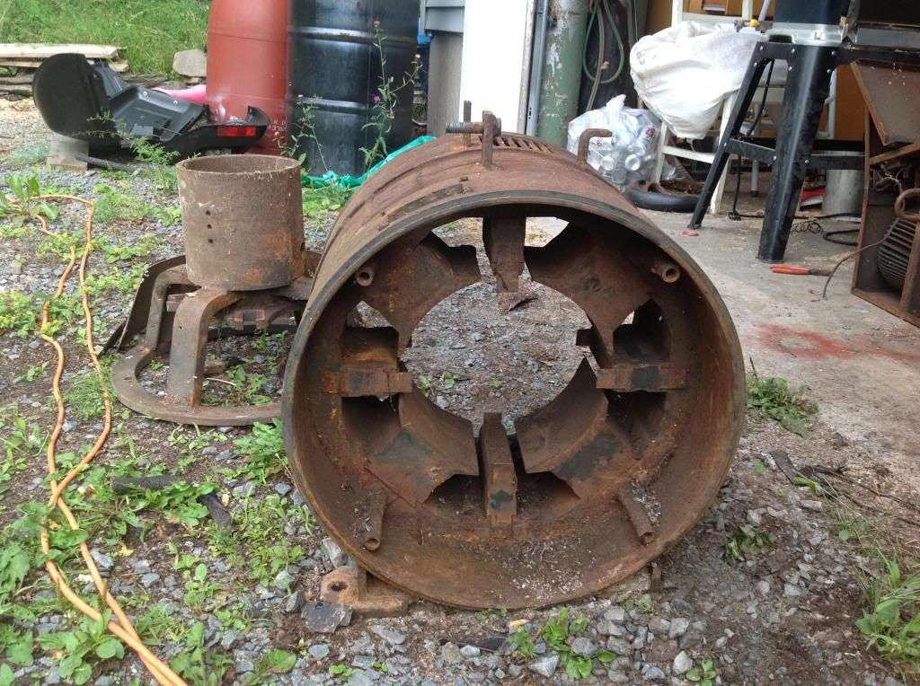
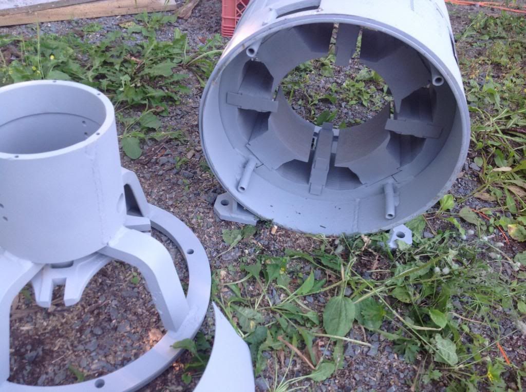
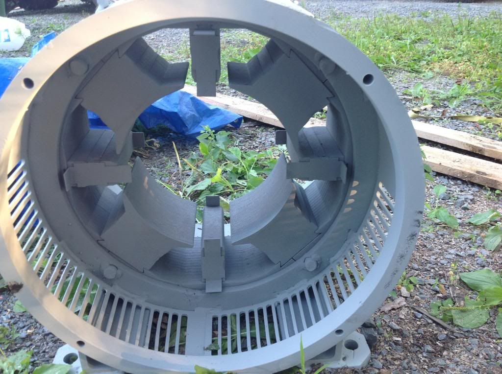
                Outside of stator has enamel primer, inside is bare metal, looks like the primed metal. She's nice and clean now.

                Cornboy, I am using metal film. I have 3 ohm on gates now, will try tonight, then keep going, till we have success. Btw, I actually run a Valtra forestry tractor and Nokia loader, from Finland. But if I said Valtra green no one would have known what I was talking about.

                Comment


                • Old Boy.

                  Great Machine, you may need more than 3 ohm to stabilise the gates and make them sharp switching. It's sure worth a try.

                  Man that's one hunk of iron, love the way it's made with dovetails, and modular, for ease of winding.

                  I am an Old Boy, but no experience with Tubes i'm afraid.

                  Regards Cornboy.

                  Comment


                  • SHE Looks grrreat!

                    Originally posted by machinealive View Post
                    Hey UFO

                    She's home.


                    Outside of stator has enamel primer, inside is bare metal, looks like the primed metal. She's nice and clean now.

                    Cornboy, I am using metal film. I have 3 ohm on gates now, will try tonight, then keep going, till we have success. Btw, I actually run a Valtra forestry tractor and Nokia loader, from Finland. But if I said Valtra green no one would have known what I was talking about.
                    Hello Friend!

                    That Baby looks grrrreat!

                    Could you just make a small video, or pictures in a sequence...that shows how to arrange all parts involved?

                    So I could give you my opinion on further development...

                    I believe you've got there a perfect "prospect" to do some test to honor the excellent work of Figuera's Generators!


                    Beautiful Machine She will be!


                    Warm Regards


                    Ufopolitics
                    Principles for the Development of a Complete Mind: Study the science of art. Study the art of science. Develop your senses- especially learn how to see. Realize that everything connects to everything else.― Leonardo da Vinci

                    Comment


                    • Hello to ALL...

                      Hello My Friends,

                      I feel it is about time for You All to start "seeing" beyond our typical and "rigid" Machines...

                      I believe You All could handle it by now...

                      One thing I will need from You all...please, open Your Minds, open them to possibilities beyond "The Standards"...the "Typical"...that we all know/ have learned so far...please do it...

                      First, disregard the "Rotating-Mechanical-Means", please, forget about a "Radical and Rigid, Center Shaft"...forget about the rotating "means"...as long as they keep a "Virtual Center", as long as they keep a "steady air gap"...it could be "Axial"...or it could be "Radial"...it really does not matters...they are just "colors" to "paint" your "backgrounds"..., so let's concentrate in the "Main Issues"...

                      I have made the following drawing for you ALL to analyze...(please note, there is not a center shaft...a center "CAD cross"...limiting our imagination...

                      [IMG][/IMG]

                      In the picture/CAD above, I have drawn a Ten Pole Machine...but then again, it could be a 3, a 12, a 20, a 21...a 28...or a thirty six (36)..., the number of poles is completely "relative"...

                      However, if you all notice, I have made all rotating poles structures "INDEPENDENT", meaning isolated not only by their coils, but also by Independent Steel CORES MODULES...that still, rotate around a "virtual center"...or a "Real One"...don't matter...they rotate, period.

                      I have incorporated a more "Solid" Stator System...Inner and Outer Stators...in order that "Electro-Magnetic-Inter-Actions" , (for Motor) would be MUCH Stronger/Robust...than just based on a "Single Row" of Stators...We have seen so far...

                      Now, please....let's move/step into Figuera's Generator Patents...

                      Who in this entire Planet, could prevent Us...from Inserting Independently "Induced/Generating Coils"...within Our Asymmetrical (Rotor) Armatures?!


                      No One...


                      The Brown Coils are just that..."Inducing Coils" within our Motor Armatures...and they will be rotating around a "Steady Belt" of Inner-Outer Solid Stators...That -for Patent Means- they "could also be" ...INNER and OUTER EXCITING FIELDS...

                      Now, the way we set them...is completely...up to Us...We could apply their magnetic "influences" from our Motor Actions, We could "Match" Motor Interactions...and they would be stronger, assisted by the "Transformer Actions" at every pulse...right?...Right!


                      What moves...and what don't?...Stators/Exciting Fields or Armatures/Induced Coils...is completely up to your best choices/judgement calls...according to your applications...according to sizes...small, medium, big?...no problema...go for it!


                      Your Minds would be your own limitations , My Dear Friends...


                      Why did I post this?...because I feel it is about time... I just started "Opening" your minds, my dear friends...into "wider" Horizons...


                      Asymmetrical Systems WILL open MANY possibilities to "Play" around with our future designs...and then some more...


                      Go over this design...make it happen within your minds...rotate them...interact them...make them work...I am just "A Channel"...to bring it up to you My Friends...You could "modify them"...as you please.

                      Edit 1: I did NOT wanted to start uploading lots of CAD's/Abstracts/Descriptions of weird (to you) designs...without a brief discussion of this new Machines/Options...and applying them to our Disclosed knowledge on this Thread...

                      Thank You.


                      Kind Regards to All.


                      Namaste and Much Light!


                      Ufopolitics
                      Last edited by Ufopolitics; 08-08-2013, 07:05 AM.
                      Principles for the Development of a Complete Mind: Study the science of art. Study the art of science. Develop your senses- especially learn how to see. Realize that everything connects to everything else.― Leonardo da Vinci

                      Comment


                      • @UFO:
                        Thanks for disclosure! Need to dig into Figueras thoughts (in fact Tesla's prior work)
                        1.
                        My mind hit a limitation I ponder on.
                        How is the flux flow between 2 north poles / south poles respectively? They oppose - in fact there are two opposing vortices. Coils might change between no flux N and no flux S.
                        I am sure my "limitation" is not really existent. I might need to know some additional facts, might be the foundation of teh magic I missed..

                        2. My mind would like to see magnets rotating in order to have easy access to coils.
                        JS
                        Experts spend hours a day in order to question their doing while others stopped thinking feeling they were professionals.

                        Comment


                        • Discussion

                          Originally posted by Ufopolitics View Post
                          Hello My Friends,

                          I feel it is about time for You All to start "seeing" beyond our typical and "rigid" Machines...

                          I believe You All could handle it by now...

                          One thing I will need from You all...please, open Your Minds, open them to possibilities beyond "The Standards"...the "Typical"...that we all know/ have learned so far...please do it...

                          First, disregard the "Rotating-Mechanical-Means", please, forget about a "Radical and Rigid, Center Shaft"...forget about the rotating "means"...as long as they keep a "Virtual Center", as long as they keep a "steady air gap"...it could be "Axial"...or it could be "Radial"...it really does not matters...they are just "colors" to "paint" your "backgrounds"..., so let's concentrate in the "Main Issues"...

                          I have made the following drawing for you ALL to analyze...(please note, there is not a center shaft...a center "CAD cross"...limiting our imagination...

                          [IMG][/IMG]

                          In the picture/CAD above, I have drawn a Ten Pole Machine...but then again, it could be a 3, a 12, a 20, a 21...a 28...or a thirty six (36)..., the number of poles is completely "relative"...

                          However, if you all notice, I have made all rotating poles structures "INDEPENDENT", meaning isolated not only by their coils, but also by Independent Steel CORES MODULES...that still, rotate around a "virtual center"...or a "Real One"...don't matter...they rotate, period.

                          I have incorporated a more "Solid" Stator System...Inner and Outer Stators...in order that "Electro-Magnetic-Inter-Actions" , (for Motor) would be MUCH Stronger/Robust...than just based on a "Single Row" of Stators...We have seen so far...

                          Now, please....let's move/step into Figuera's Generator Patents...

                          Who in this entire Planet, could prevent Us...from Inserting Independently "Induced/Generating Coils"...within Our Asymmetrical (Rotor) Armatures?!


                          No One...


                          The Brown Coils are just that..."Inducing Coils" within our Motor Armatures...and they will be rotating around a "Steady Belt" of Inner-Outer Solid Stators...That -for Patent Means- they "could also be" ...INNER and OUTER EXCITING FIELDS...

                          Now, the way we set them...is completely...up to Us...We could apply their magnetic "influences" from our Motor Actions, We could "Match" Motor Interactions...and they would be stronger, assisted by the "Transformer Actions" at every pulse...right?...Right!


                          What moves...and what don't?...Stators/Exciting Fields or Armatures/Induced Coils...is completely up to your best choices/judgement calls...according to your applications...according to sizes...small, medium, big?...no problema...go for it!


                          Your Minds would be your own limitations , My Dear Friends...


                          Why did I post this?...because I feel it is about time... I just started "Opening" your minds, my dear friends...into "wider" Horizons...


                          Asymmetrical Systems WILL open MANY possibilities to "Play" around with our future designs...and then some more...


                          Go over this design...make it happen within your minds...rotate them...interact them...make them work...I am just "A Channel"...to bring it up to you My Friends...You could "modify them"...as you please.

                          Edit 1: I did NOT wanted to start uploading lots of CAD's/Abstracts/Descriptions of weird (to you) designs...without a brief discussion of this new Machines/Options...and applying them to our Disclosed knowledge on this Thread...

                          Thank You.


                          Kind Regards to All.


                          Namaste and Much Light!


                          Ufopolitics


                          Thanks for this UFO, as you know i have the blinders on, as far as where i need to head, with what i am doing here, so all my, investigations/experimenting/ building, head to EV propulsion-- High Torque and Horsepower, and of course one part of a motor stationary, and the other opposing part, rotating for power delivery.

                          Trying to imagine the design without an output shaft/ coupling of some sort is hard!.

                          I have always wondered how the transformer effect of our normal electric motors, with solid flux path, through the entire rotor, could be helping or hindering performance.

                          To have clearly seperated cores for rotor and stators, i am sure could only help performance, not to mention the use of both north and south stator fields, simultaniously.

                          Just don't go spinning stator fields seperatley, or you will strain my brain permanently!

                          So UFO, if you had this design with say 36 inner and outer, seperate, stator coils, and 36 inner seperate rotor coils, drum fashion, all pulsed, at once for very short time, or sequencially pulsed, as needed, whould that be too symetrical?.

                          I also understand that this design is to open discussion, on possibilities, and i look forward to that.

                          Warm Regards Cornboy.

                          Comment


                          • Hey folks

                            Last night I tried the driver with 3 ohm resistors at gates, and I stopped killing resistors, but rpm was only at 450 max. So I re-connected relays, and back to 950 at 12 v. I'm gonna stay with this for a bit. Having too much fun.


                            Johnstone, on the diagram, stators are correct. If red is south on the outside of magnet, then it is north on the inside of same magnet. So the north of outer stator is facing the south of inner stator, and the inner stator's north points in to centre. I think.

                            I'll make a little video of the parts today UFO. Mr. Clemente, here we come.

                            Comment


                            • Thanks John!

                              Originally posted by JohnStone View Post
                              @UFO:
                              Thanks for disclosure! Need to dig into Figueras thoughts (in fact Tesla's prior work)
                              1.
                              My mind hit a limitation I ponder on.
                              How is the flux flow between 2 north poles / south poles respectively? They oppose - in fact there are two opposing vortices. Coils might change between no flux N and no flux S.
                              I am sure my "limitation" is not really existent. I might need to know some additional facts, might be the foundation of teh magic I missed..

                              2. My mind would like to see magnets rotating in order to have easy access to coils.
                              JS
                              Hello John!

                              Yes, My Mistake...You do not have to ponder...Just have to turn either Inner or Outer Stators/Exciters about 90 degrees from the other one...it should be N-S at each "face to face" .

                              I did the whole thing too fast last night...


                              Thanks, I will correct picture when back to files

                              Warm regards


                              Ufopolitics
                              Principles for the Development of a Complete Mind: Study the science of art. Study the art of science. Develop your senses- especially learn how to see. Realize that everything connects to everything else.― Leonardo da Vinci

                              Comment


                              • Hi UFO,
                                If my mind was any more open my brain might fall out.
                                Could I assume by looking at the drawing that one could add more or as many stator - armature rings as one wanted?

                                Comment

                                Working...
                                X