Announcement

Collapse
No announcement yet.

My Asymmetric Electrodynamic Machines

Collapse
X
 
  • Filter
  • Time
  • Show
Clear All
new posts

  • Hey UFO

    I have been trying not to look at your new stuff, because I don't want to get distracted from this programming journey. I am recording rpm, and one temp for brush, I going to start at current sensor, voltage dividers next.

    But, I had to look at the designs, I love those big fat, tires? We really are gonna
    Re-invent the wheel. My imagination is out of control.


    Hey UFO, you look much younger then I imagined. .

    Anyway, back to the books, as soon as I'm done I'm starting the generator.

    Hey Cornboy, do you have a material in mind, for rotors, etc. , I know what I would like to try using, but then there can be no permanent magnets.

    Machine

    Comment


    • Originally posted by machinealive View Post
      Hey UFO

      Anyway, back to the books, as soon as I'm done I'm starting the generator.

      Hey Cornboy, do you have a material in mind, for rotors, etc. , I know what I would like to try using, but then there can be no permanent magnets.

      Machine

      G'day machine
      When I was looking/building Bedini Oscillators there was quite some discussion regarding materials that do not retain magnetism when pulsing
      one in particular was a paramagnetic material I think from Canada I could be wrong
      It was supplied by Jeremy Chambles "
      If I remember correctly I think Dana used some and Bob French also was the one who introduced and called it "Paracore" us to it, I have purchased some but as yet have not had a chance to try it I have been tooo busy with building UFO's in the shape of bycycles
      I am sure if you get in touch with Bob French he can enlighten you more about it here is his contact
      mailto:bobfrench@fastmail.fm

      Kindest Regards

      Kogs still here trying to be helpful

      Comment


      • Hey Machine, Kogs Et al, i have tried iron powder with resin, also with a little copper and aluminium powder mixed in, also Paul Babcock reccomends, # 7 soft iron shotgun pellets, with a coat of cheap acrylic paint and then mixed with resin and poured.

        What ever is used it has to have high magnetic strength, to produce torque. When i finally get my first Monster built i will pulse some coils i have with iron powder cores and vid it for you.

        Cheers Cornboy.

        [IMG][/IMG]

        Comment


        • Hi, UFO
          Originally posted by Ufopolitics View Post
          Hello to All,


          A New Method to replace the Old Brush Systems...and mount our contacts in Roller Bearings...

          Bearings chosen for this design, must heave Metal Seals, NOT Plastic!

          All we need to do is build a simple mounting bracket with pressure springs like shown on Picture below:

          [IMG][/IMG]

          And press fit a copper ring at outer diameter, this will be our replaceable contact part, just like a brush.
          What I recommend is to search first for a copper tubing of specific diameter, then locate a bearing that will fit by pressing it tight. Now, the Thicker this ring, the longer its life span.

          The advantages are given by better rotating mechanisms that will eliminate the drag and friction caused by previous method. As avoiding fast deterioration or accumulation of carbon deposits at commutator elements and gaps.

          [IMG][/IMG]

          Many more improvements could be done here...as oil sponges rubbing opposite side of bearing, a conductive grease of course, inside housings...

          This system if well built could handle very high speeds, much faster than linear pressure carbon brushes.
          The Outer Ring (Consumable) could also be made out of Carbon Fiber, but processed with a very high temperature/hard solid epoxy resin.

          [IMG][/IMG]

          This System will also provide a smooth and precise adjustment of timing while Machine is rotating, even at very fast speeds.

          I will be rendering a video further on, about this simple but enhancing tech.

          Regards to all


          Ufopolitics
          Very impressive

          Regards

          Comment


          • Thanks Cornboy, Koggs, para core, maybe Dana knows about it.

            Hey Cornboy, it's sounds like you have a short on your driver. Sounds like your measuring your input voltage to your 5 v regulator minus a voltage drop acrossed a diode.

            Comment


            • Well in an Epic RAP Battle of Tesla vs Edison I would have to say Edison won.. but Tesla has a point. He was stolen from Mankind.

              Edison vs Tesla Rap Battle!!

              Comment


              • Contact! We have lift off!

                Ace,

                I agree with you! Those roller contacts are hot!!! If they were almost the same size as the comms, would they reduce the losses and sparking at comms? I would really like to see them spinning super hard in the dark!


                Palmoni,

                Cool little rap song. I had to listen to it twice. Yeah, Edison was talking mad _hit! Tesla has to come back harder in the future!

                @ All

                It's nice to see the group being more creative and having more fun!

                Keep it Clean and Green
                Richie

                Comment


                • Originally posted by machinealive View Post
                  Thanks Cornboy, Koggs, para core, maybe Dana knows about it.

                  Hey Cornboy, it's sounds like you have a short on your driver. Sounds like your measuring your input voltage to your 5 v regulator minus a voltage drop acrossed a diode.

                  Yeah it does Machine, i checked another board and there is no transfer accross any of the grounds to positive, and why only on the 5v ic, i think it must be a cap shorting.

                  Will remove caps to see, Just as well i am doing this in baby steps, as JS recomended, imagine powering up the whole driver only to keep blowing components everywhere from overvoltage etc!.

                  Regards Cornboy.

                  Comment


                  • Midas, you sound like your having Toooo much fun.

                    Cornboy.

                    Comment


                    • @ Cornboy

                      I like to see creative minds at work and sharing ideas openly! Now that's progress and harmony!


                      Keep it Clean and Green!
                      Richie

                      Comment


                      • Cornboy
                        Have you put in the jumper yet? That is the problem as with no ground, you are getting normal readings.
                        Dana
                        "Today's scientist have substituted mathematics for experiments and they wander off through equation after equation and eventually build a structure which has no relation to reality."
                        Nikola Tesla

                        Comment


                        • Mechanical design observations

                          Hi UFO, from your post 5294

                          Originally posted by Ufopolitics View Post

                          [IMG][/IMG]

                          On the Diagram above (which is NOT a FULL CAD Design, strictly made for reproduction on Reality) I am displaying a "Future" Imperial transformed into a Dual Rotor System...and like I have mentioned before, this design is a "Buffer" between my Patent of Shaft Less Machines and a "Traditional" Shaft Motor.

                          On the General Concepts..I call this Winding Method a "Caliper Design Armature", since We have Outer P1 and an Inner P1 EMBRACING Stators, As We could conceive this "Relation" to be developed in an "AXIAL" or "RADIAL" Fashion (The one shown here is Radial, of course)...Coils/Pairs are on the same Circuit as We have built before...same winding type, same Bisectors, same Timings...except that now we are "Interacting" also with the outer Stators Magnetic Fields, which are reverse, according to the Typical Convention we have utilized so far (and here it ca
                          On the Stators Bounding/Supporting Structures, I have conceived Four "H" Beams (Ooops!!... I mentioned the "H Word"!!... )...Now, Two of This Structures, situated at 180º ...We could use our same existing Bolts Holes that joins/connect Both End Caps to Main Frame as a guide. I rather choose Aluminum for this "Members/Beams", and in the 3D Video, you would be able to see the additional curved cross sections that would add more strength as it will become a Solid Space Frame Structure, once all get connected/bolted on. This Beams will be connected to ONLY one Side Cap

                          On the Dual Rotor "Bridge Structure", it consists of a Pattern that comprehends Inner and Outer Arms full length (since they are completely aligned) and Bolts at Inner and Outer Extremes , Structure ends in Inner-Outer Rings for bolting them to Steel Laminations (Not Shown on this Diagram)...It could also be conceived on Aluminum, bolted on before Winding...and covered with Epoxy Insulating Resin before...Now, this Bridge ONLY goes on ONE Side of Rotor...of course, the Opposite to where Stators H Beams attach to.

                          To do the "Final Attachment" from Upper (Rotor) and Lower (Stator) Structures, We use External "[ ]" Brackets, from Cap to Cap. that "Not necessarily need to be a Massive Steel Cylinder Either...Remember, at Outer Rotor we could add our Capacitors "Belt"...and will give us easier access to check them, replace them...read them, etc,etc...

                          It would be understood that EVERY Parameter or "Attribute" of our so far existing Machines Structures ...would be enhanced, at least, doubling our previous output performance...

                          Ufopolitics
                          Hi UFO. looks fantastic. Tough to visualize the structure between the inner and outer rotors. Stators are still stators but are now fastened to an endcap in a structure instead of to the body I guess? Definite machine shop activity then to build. Wow that outer rotor just doesn't exist and would have to be custom built. Big step up for a homebuilder, maybe except for Cornboy bye bye reusable symmetric motors. The inner and outer rotor are still encased as opposed to that gemini machine right? Torque still delivered at the shaft? Don't blow my mind with that shaftless thingy just yet OK So the brushplate on the stator mount endcap would have to fit amongst the stators somehow too? By that time I hope I have a real motor manufacturer interested...
                          Last edited by sampojo; 08-25-2013, 03:46 AM.
                          Up, Up and Away

                          Comment


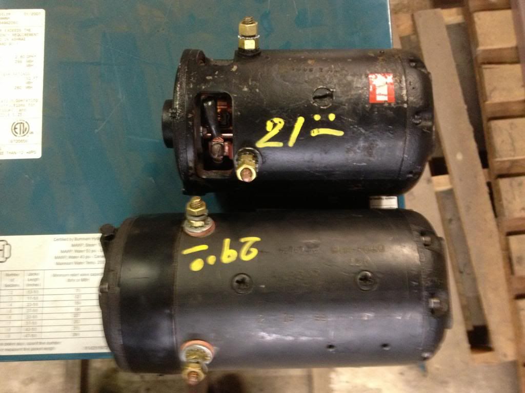
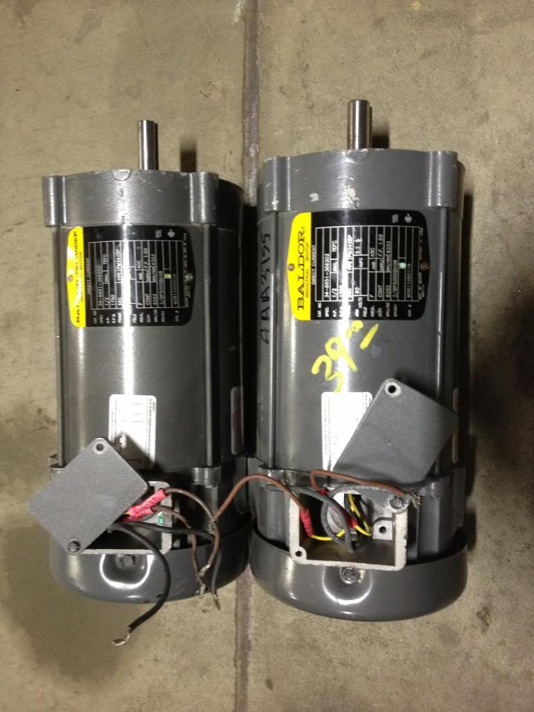
                          • local motor goldmine less than 4 mi. from my home!

                            pays off. Check out these half horse Baldors. As UFO pointed out they are 2 brush motors, seems to say that on the label. looking forward to the conversion to a 4 stator as I did on my QP10.
                            Hoping to share parts from the 3/4hp Baldor I found on another shelf. My count is that I am still short 2 brushes. All three motors plus a small 3000 rpm shade pole I am going try to convert to an induction generator
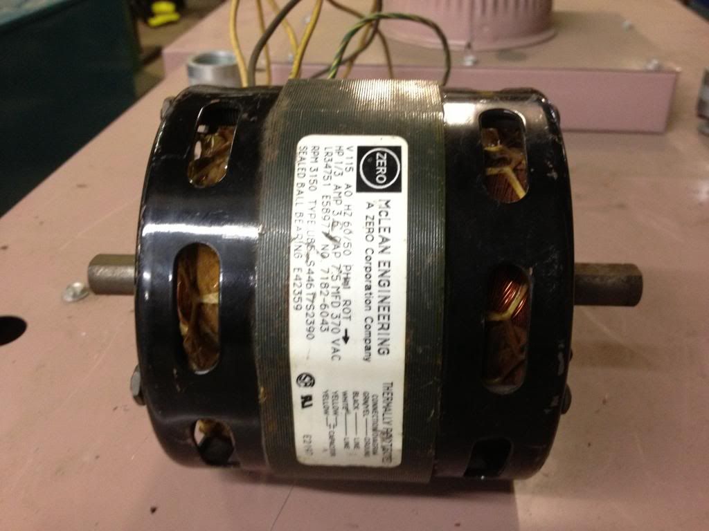
                            to see what my QP10 can do cost me less then buying a brush plate & brushes probably. got him to knock a few buck off with the bulk buy

                            Check out these motors, a little smaller, but 4 stator. Looks pretty similar, maybe same manufacturer, no labels on them
                            they are really heavy. Oh well just dreamin', maybe if I was retired....
                            Up, Up and Away

                            Comment


                            • Hello Sampojo, Hello All

                              Originally posted by sampojo View Post
                              Hi UFO, from your post 5294
                              Hello Sampojo!


                              Hi UFO. looks fantastic. Tough to visualize the structure between the inner and outer rotors. Stators are still stators but are now fastened to an endcap in a structure instead of to the body I guess? Definite machine shop activity then to build.
                              Thanks my friend, yes, Stators are fastened/tightened between them first, through the joining vertical elements, then, those elements "legs/fasten" to the End Caps. Elements look like an "L", where bottom fasten to lower structure.


                              Wow that outer rotor just doesn't exist and would have to be custom built. Big step up for a homebuilder, maybe except for Cornboy bye bye reusable symmetric motors.
                              Not really...The Outer Rotors could be "hunted" from many different sources...

                              1-The Outer Stators , or better said..."The Generating Fields" of a Car Alternator...

                              2-The Outer Coils of an "Inrunner" Brushless DC Motor (The ones that have a permanent magnet Rotor Drum)

                              3-The "Megaflux Frameless Torque Motors"...However, this option would be very expensive...I believe.

                              Now, the problem could be to find the right Arc Circumference Magnets that would fit within those outer rotors, and still allowing a very small air gap...

                              And nope, do not say "goodbye" to the Old Symmetrical Motors yet...We could reuse all their "guts"...like Armature, Permanent Magnets Stators and brushes/holders...etc.

                              The inner and outer rotor are still encased as opposed to that gemini machine right? Torque still delivered at the shaft? Don't blow my mind with that shaftless thingy just yet OK So the brushplate on the stator mount endcap would have to fit amongst the stators somehow too? By that time I hope I have a real motor manufacturer interested...
                              Have no idea about the "Gemini" Machine...sorry, and yes, torque still delivered through shaft...LOL...Do not worry, No shaft-Less Motors yet...

                              Sampojo...look at it like a "Fatter" typical old Symmetric Motor, where we "Beef/Engross" the Existing Rotor, by extending it to an Outer one, that "jumps" to Interact with Stators on the other side... taking off the "Bulky and Heavy" Stators Frame, and replacing it by Elements between them, and attached to One End Cap...

                              The bottom End Cap where Stators Elements mount can house the brush holders board perfectly...do not picture in your mind a Full Enclosed Cylinder holding the Magnets anymore...but figure Stators Mounted on Four Legs...

                              Do You know what "Space Frames Structures" are?...They are based on Tubular pieces of "elements" joined between them...configuring any structure required...without the need to have Huge Solid Beams or Huge Columns...etc,etc

                              [IMG][/IMG]

                              Many Exotic Cars are built based on Tubular Space Frames...like Ferrari, Lamborghini...Bugatti...etc

                              Now, we could build our Future Asymmetric Motors with Space Frames...right?

                              Permanent Magnets or Wound Stators mounted through Space Frames...

                              End Cap to End Cap assembled through Space Frames also...then cover the Outer Space Frame Structure with a Mesh to prevent foreign particles to enter our Machines...

                              Many light but Super Strong Materials could be used...like Kevlar, Carbon Fibers or high Grade Strength Aluminum.

                              In general, the weight of the whole Assembly...would be considerably reduced...


                              Warm Regards Friend


                              Ufopolitics
                              Principles for the Development of a Complete Mind: Study the science of art. Study the art of science. Develop your senses- especially learn how to see. Realize that everything connects to everything else.― Leonardo da Vinci

                              Comment


                              • Bridging our Dual Rotor System...

                                Hello Guys,

                                Here is a CAD 3D of what could be a method to Bridge Outer-Inner Rotors...

                                [IMG][/IMG]

                                And...for "possible" further questions...the answers...

                                1-Of Course they do not need to be just Four...could be Three...Eight...or Twenty Eight...your choice according to Application Torque/Strength required..

                                2-Of course this structure could also be utilized as a fan to keep cool both Rotors Coils...just an "Angular Inclination" of Top "Fins"....according to rotation sense...

                                3-Of course we could wind Inner/Outer rotors separately ...just labeling Pair numbers...then match/attach their corresponding terminals at Commutators Elements...or Internal P1 to External P1...then bolting up Inner-Outer Rotors...

                                4-Yes...We could "Split" them into just "basic" isolated structures...like separating them into four, every 90º (applicable to this drawing)

                                And of course this Structure will not "conflict" with Brushes.Commutators or Coils height...

                                [IMG][/IMG]

                                Next Diagram I will show Stators Space Frame Elements...


                                Warm Regards


                                Ufopolitics
                                Principles for the Development of a Complete Mind: Study the science of art. Study the art of science. Develop your senses- especially learn how to see. Realize that everything connects to everything else.― Leonardo da Vinci

                                Comment

                                Working...
                                X