Announcement

Collapse
No announcement yet.

My Asymmetric Electrodynamic Machines

Collapse
X
 
  • Filter
  • Time
  • Show
Clear All
new posts

  • Small update

    @ Team Up,

    Moved the CBR 250 into the garage. Took off the radiator, muffler and removed the motor today. Everything went fine but I had one problem.....

    Went inside to take a phone call. Came back out, saw the cap to the oil tank off. Though that some one drained the oil. Proceeded to take the last bolts off from the motor mounts. As I lowered the engine, my phone rang again. It seemed stable so I went to answer my phone. And boom! It fell over. I heard it fall but I didn't think anything of it. Came back, oil spilled all over everywhere. Big mess

    Spent the rest of the day cleaning the frame and talk to customers about the Electric motorcycle project.


    Cheers

    Keep it Clean and Green
    Midaz
    Last edited by Midaztouch; 09-13-2013, 03:19 PM.

    Comment


    • Please...Pictures of Process?

      Originally posted by Midaztouch View Post
      @ Team Up,

      Moved the CBR 250 into the garage. Took off the radiator, muffler and removed the motor today. Everything went fine but I had one problem.....

      Went inside to take a phone call. Came back out, saw the cap to the oil tank off. Though that some one drained the oil. Proceeded to take the last bolts off from the motor mounts. As I lowered the engine, my phone rang again. It seemed stable so I went to answer my phone. And boom! It fell over. I heard it fall but I didn't think anything of it. Came back, oil spilled all over everywhere. Big mess

      Spent the rest of the day cleaning the frame and talk to customers about the Electric motorcycle project.


      Cheers

      Keep it Clean and Green
      Midaz
      Hello Midaz,

      Sorry about the "BP Small Spill"...

      It is great to know you are advancing in your project electric bike, awesome!

      Could You please...ornament your posts with some nice pictures of your bike...as the whole process?...it would be awesome to see it also...


      Thanks and Kind Regards


      Ufopolitics
      Principles for the Development of a Complete Mind: Study the science of art. Study the art of science. Develop your senses- especially learn how to see. Realize that everything connects to everything else.― Leonardo da Vinci

      Comment


      • Hello Sampojo, Hello All

        Originally posted by sampojo View Post
        Test results:
        Just used old TV polarized caps as running caps as demo'd at the induction motor conversion site and got the motor to generate by doing exactly what was explained at the Induction Generator site. Couldn't get the induction motor to run as motor though as it had connections for a starter cap I assume which I did not have. But shocking the motor with 110v as trying to run it seemed to allow it to generate when rotated. I can't say for sure that there is nothing wrong with my induction motor-gen at this point I realize also. However my QP4 10-pole was not up to the task, could not get over 1500 rpm using 2 brush sets, had 23vac on the gen side. AND of course smoke-checked a brush set. Used solder to connect the brush wire to the outside wire and I think it probably melted. Autopsy to follow. I thought the induction generator would not load up that much without any electrical load on spin-up.

        Possible solution: I have a 1725rpm motor, but my QP4-10pole still gets hot
        Hello Sampojo, Hello All,

        Hey, realize that if having a Four Pole Stator/Generator...it should require only 1800 RPM's to output 120/60 Hertz Cycle...not 3600.

        My question is:

        Are You feeding Linearly/Straight the QP4-10...Or Pulsing it?

        If You are doing it "linear" expect that it would overheat...since there is "no brake" from Power Source.

        If Your Quad Penta is overheating while Pulsing it, this means you need to rise the resistance per coil/pairs...more copper, more turns...or a bit finer gauge...not "too much" though...but enough to allow more turns.
        Although, you could try by adding a small resistor 1 Ohm/5-10 Watts per coil/pairs.

        Great Testing you are making so far and good luck!!


        Kind Regards


        Ufopolitics
        Last edited by Ufopolitics; 09-14-2013, 05:37 PM.
        Principles for the Development of a Complete Mind: Study the science of art. Study the art of science. Develop your senses- especially learn how to see. Realize that everything connects to everything else.― Leonardo da Vinci

        Comment


        • Originally posted by machinealive View Post
          Hey UFO

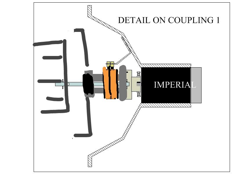
          Here, the slip ring will be compressed on a coupler with a bearing in the end, to spin around shaft, then bolt to imperial coupler at other end.


          The black blob at the end, is another bearing. Who needs cad anyway,
          Hello Machine, nice "CAD" Man!!...

          Hey, the important side is that we all understand each others...right?!

          So, I see, what you are making ...or:

          [IMG][/IMG]

          That "C" Pattern Coupler to Slip Ring and Imperial and Drum...could be done in two pieces, male-female pressed in, in order to be able to extract/insert slip ring ...right?

          Or like:

          [IMG][/IMG]

          I was also thinking of making Drum into two pieces (I explained that to you before) One, a Star Shaped Bracket that will attach to this C Coupler, and Two, the Vertical Drum containing windings...and the Star will bolt on to Cylindrical Drum...that way other Drums could be exchanged easier, by just disconnection from Star Bracket, and sliding it through bottom of assembly (after unbolting wires from slip ring, of course).

          If You noticed in above diagram, on top set up (above Axis) I set the "Male Coupler" from the "C" Bracket to be also the Star Bracket...or just one piece...simplifying design.

          The Male-Female Coupling of "C" could be done not pressed in, but easy insert (no force required) with male-female splines like I wrote before on differentials and shafts couplers utilize...

          I like that Dual Bearing on Top connections, at Imperial and at lower C Coupler...


          Excellent my Friend!


          Kind Regards


          Ufopolitics
          Last edited by Ufopolitics; 09-14-2013, 07:59 PM.
          Principles for the Development of a Complete Mind: Study the science of art. Study the art of science. Develop your senses- especially learn how to see. Realize that everything connects to everything else.― Leonardo da Vinci

          Comment


          • Hey UFO

            Finished my new imperial. This one does not have the comms widened. At 36 v DC, motor did 2830 rpm, at 10.5 amps. This 100 rpm less, and 1 amp more more then with previous build. I believe this is due to the timing, as it is not a big difference.
            I think I'll install the other imperial into gen frame, this one is mounted on rails now, I'd like to keep playing with timing.
            Now I can finish new plate, and not shorten imperial frame.

            Midas we all want lots of pics of the build, vids would be great.

            Comment


            • Re Ufo reply post 5424 mini QP4p10-induction gen setup

              Originally posted by Ufopolitics View Post
              Hello Sampojo, Hello All,

              Hey, realize that if having a Four Pole Stator/Generator...it should require only 1800 RPM's to output 120/60 Hertz Cycle...not 3600.

              My question is:

              Are You feeding Linearly/Straight the QP4-10...Or Pulsing it?

              If You are doing it "linear" expect that it would overheat...since there is "no brake" from Power Source.

              If Your Quad Penta is overheating while Pulsing it, this means you need to rise the resistance per coil/pairs...more copper, more turns...or a bit finer gauge...not "too much" though...but enough to allow more turns.
              Although, you could try by adding a small resistor 1 Ohm/5-10 Watts per coil/pairs.

              Great Testing you are making so far and good luck!!


              Kind Regards


              Ufopolitics
              Thanks, yes not a total failure, just a weak motor, overestimated size of generator or it may have needed some more work too. And any old shade pole might be able to get some good generation. I just wanted to see what kind of useful work my mini 4-stator could do, and what kind of power ratio I could get out of it. I needed 3000 rpm since the AC motor turns 3000 rpm at 60cps.

              I have not tore apart my QP410P to see the failure, but aside from its anomalous heating near the bearing and brushes, the shaft itself was getting a bit hot also. Coils never got hot, brush and comms maybe a bit warm I think. I used solder on the brush wire to the outer wire. Just not getting a good temp there? I suspect that is what gave out, but brush holders were plastic, too. I did not get an amp reading under load but I just left it run too long given its weaknesses. Its coils are about 2ohm. And yes, it was a linear feed. So you convince me try again using pulsing (As soon as I get some built, I have been neglecting that), maybe can get continuous performance under load in those conditions? As the QP410P window motor now has a heavy all alum motor body and a heavy steel endplates, it should be able to dissipate some heat. Would extra holes help? Other plastic components in brush assembly worry me. But I did raise the wire gauge from 24 in the symmetry winding to 26 for the Quad pent asymm winding. I can try my 1725rpm shade pole too when I get my pulsers built.

              All this is overshadowed as the real problem is the motor is too small. So I really like the idea of stepping up to my Baldors, focusing on minimum redesign. It looks really easy as the brushed endplates are interchangeable with the plain endplates, and are rotatable to any orientation, and the shaft is long enough too!! And then treating the 20-pole rotor as a big radioshack 5-pole motor, thats easy too.
              But here is my question for you UFO. should I use the Dual Pentagon Y winding pattern, post 1466 or the Enhanced Pentagons Post 4484? You introduced that last April, and it sounds like PERFECT, lower amperage, higher torque & rpm, and good as a generator! That would put me on the hunt for a 4th Baldor I think to make a generator, and then I'd be looking for a grid tie inverter after that! Definitely leaning this way. Were you suggesting something special with the original RS asymm winding? Does that Enhanced Pentagon design use spools in winding?

              Thanks, man
              Last edited by sampojo; 09-15-2013, 04:16 AM.
              Up, Up and Away

              Comment


              • Hello Sampojo

                Originally posted by sampojo View Post
                Thanks, yes not a total failure, just a weak motor, overestimated size of generator or it may have needed some more work too. And any old shade pole might be able to get some good generation. I just wanted to see what kind of useful work my mini 4-stator could do, and what kind of power ratio I could get out of it. I needed 3000 rpm since the AC motor turns 3000 rpm at 60cps.

                I have not tore apart my QP410P to see the failure, but aside from its anomalous heating near the bearing and brushes, the shaft itself was getting a bit hot also. Coils never got hot, brush and comms maybe a bit warm I think. I used solder on the brush wire to the outer wire. Just not getting a good temp there? I suspect that is what gave out, but brush holders were plastic, too. I did not get an amp reading under load but I just left it run too long given its weaknesses. Its coils are about 2ohm. And yes, it was a linear feed. So you convince me try again using pulsing (As soon as I get some built, I have been neglecting that), maybe can get continuous performance under load in those conditions? As the QP410P window motor now has a heavy all alum motor body and a heavy steel endplates, it should be able to dissipate some heat. Would extra holes help? Other plastic components in brush assembly worry me. But I did raise the wire gauge from 24 in the symmetry winding to 26 for the Quad pent asymm winding. I can try my 1725rpm shade pole too when I get my pulsers built.

                All this is overshadowed as the real problem is the motor is too small. So I really like the idea of stepping up to my Baldors, focusing on minimum redesign. It looks really easy as the brushed endplates are interchangeable with the plain endplates, and are rotatable to any orientation, and the shaft is long enough too!! And then treating the 20-pole rotor as a big radioshack 5-pole motor, thats easy too.
                But here is my question for you UFO. should I use the Dual Pentagon Y winding pattern, post 1466 or the Enhanced Pentagons Post 4484? You introduced that last April, and it sounds like PERFECT, lower amperage, higher torque & rpm, and good as a generator! That would put me on the hunt for a 4th Baldor I think to make a generator, and then I'd be looking for a grid tie inverter after that! Definitely leaning this way. Were you suggesting something special with the original RS asymm winding? Does that Enhanced Pentagon design use spools in winding?

                Thanks, man

                Hello Sampojo,

                Yes, definitively pulsing the small Pentagon Motor would bring better results than linear feed...but as you said...and as I wrote before...there must be a balance in the Armature/Rotor Mass of both machines, I wrote that when we were attaching Imperial to Meccalte...I have not seen your set up pictures of this late tests...so can not tell you about being too small for the job.

                Related to the Enhanced Pentagon...I remember that further on I posted something about this design...something that for some reason did NOT worked out the way I expected in certain arrangements...can not remember at this point what 'exactly' was ...

                The Enhanced Pentagon does not require other spools for its winding...just first Pair and then second Pair...and so on...just watch the vertical wire build up...keep pressing it down, compacting wires.

                The Baldor with the 5 pole as the RS Motor would be an excellent and simple choice....very strong and fast machine for a prime mover...I suggested to widen the gaps between joint commutator elements...but do not do this first...run it first AS IS...and observe if there are too much sparking/heating on commutator brushes...I, honestly believe that due to the size of armature and big commutator...heat would be dissipated fine.

                Also I recommended to make higher resistance values per Coils/Pairs above 2.0 Ohms.


                Kind regards friend


                Ufopolitics
                Principles for the Development of a Complete Mind: Study the science of art. Study the art of science. Develop your senses- especially learn how to see. Realize that everything connects to everything else.― Leonardo da Vinci

                Comment


                • Team UP,

                  I was so excited to see that Dana's 4 fets were cool, that I couldn't sleep. So I had to call him for more info. My wife was unhappy about that but I was!LOL

                  Woke up this morning happy but upset with myself... I didn't get Insulation paper to wind the motor. I thought I could get by without using some but Dana told me last night that I must have some.

                  I got to the garage and started cleaning. There are heavy parts and little parts everywhere! But, I have to pay my "Dues". The way I figure it, if I clean for 3 hours a day, I might be able to see the floor in...10 years! hehehe

                  I told the owner I need the insulation paper. He found insulation TAPE. After 2 hours of trying to work with what I had, we had a Tea break. Yes, a tea break. Inside under the bright lights I did an inspection.... The insulation tape doesn't seat properly at the bottom of the armatures. I tried various types of tapes. It great but it's too sticky. Tape is No good NG!

                  We talked about buying wider magnets for the Imperial. Do you guys with Imperials think I should get wider magnets for the race bike? If yes, we need a company to buy the upgraded magnets. Please search also. We need to find the best deal and easy access for everyone.

                  Since, the tape failed, I sanded the rotor.

                  I took our girl, Radiance, outside to take a pic with her big brother, a CBR1000rr Fire Blade.

                  Keep it Clean and Green
                  Midaz
                  Last edited by Midaztouch; 09-27-2013, 03:52 AM.

                  Comment


                  • About the Hendershot Generator...

                    Hello to all,

                    A Friend send me the pdf that He purchased to build a Hendershot Generator...it is based only on Coils and Capacitors...and a magnet...a fascinating design!

                    However, after seeing the way that "geometrically" are the "Storage Side" Coils and Capacitors set...I realized it is nothing but what Nikola Tesla called "An Asymmetric Capacitor" or Asymmetric "LC" Tank Circuit.

                    In another great pdf, Russian Vladimir Utkin cites about this Tesla hidden work...where an Asymmetric Capacitor would generate an "Ascending Wave Pattern" instead of what we all know so far...A Decaying Wave Pattern from any known Capacitor.

                    Everything here relates to the Geometrical Disposition Relation, between the Magnetic Field of the Coil and the Electric Field from Cap...that's all

                    When we set Cap within (meaning INSIDE) the Magnetic Field of the Coil...both Fields (Dynamic and Static) start a series of "self compensations" (may I call it that way) where both fields assist each others delivering the "Ascending Wave" We all have been looking for...

                    Very interesting "scenario" there...and I thought of sharing this knowledge with you all...This set up could definitively be applied to our asymmetric motor-generators in a near future.


                    Warm Regards


                    Ufopolitics
                    Principles for the Development of a Complete Mind: Study the science of art. Study the art of science. Develop your senses- especially learn how to see. Realize that everything connects to everything else.― Leonardo da Vinci

                    Comment


                    • A Beauty!!

                      Originally posted by Midaztouch View Post
                      Team UP,

                      I was so excited to see that Dana's 4 fets were cool, that I couldn't sleep. So I had to call him for more info. My wife was unhappy about that but I was!LOL

                      Woke up this morning happy but upset with myself... I didn't get Insulation paper to wind the motor. I thought I could get by without using some but Dana told me last night that I must have some.

                      I got to the garage and started cleaning. There are heavy parts and little parts everywhere! But, I have to pay my "Dues". The way I figure it, if I clean for 3 hours a day, I might be able to see the floor in...10 years! hehehe

                      I told the owner I need the insulation paper. He found insulation TAPE. After 2 hours of trying to work with what I had, we had a Tea break. Yes, a tea break. Inside under the bright lights I did an inspection.... The insulation tape doesn't seat properly at the bottom of the armatures. I tried various types of tapes. It great but it's too sticky. Tape is No good NG!

                      We talked about buying wider magnets for the Imperial. Do you guys with Imperials think I should get wider magnets for the race bike? If yes, we need a company to buy the upgraded magnets. Please search also. We need to find the best deal and easy access for everyone.

                      Since, the tape failed, I sanded the rotor.

                      I took our girl, Radiance, outside to take a pic with her big brother, a CBR1000rr.

                      Keep it Clean and Green
                      Midaz


                      Hello Midaz,

                      [IMG][/IMG]


                      Wow!, what a Beauty!!

                      What a SOLID and well built Aluminum Frame...and TIG Welded!...a very strong Bike indeed!...Love that Rear Suspension Fork...heavy built.

                      I see you will need to build a space frame for Battery Bank Racks...but you have plenty of room there...as also the lower center area to "house" your Imperial...nice !

                      I would "expand" the battery bank rack all the way to where the Gas Tank space goes (shaping a body shell that looks like the Tank...)

                      I would set all four Monster Pulsers in the front area, right behind upper steering fork ...stacked "vertically" then design a nice Scoop to intake air cooled to heat sinks facing forward...that would deliver super cooling temperature while driving at top speed.

                      Related to Imperial Permanent Magnets...if the Budget allows...yes, definitively I would get wider/bigger arc magnets without modifying external steel housing...meaning not thicker, but bigger Arc, in order that they would be as close as possible to each others...This modification WILL definitively enhance the torque and speed beyond original design...

                      On a separate note...is there a possibility of getting a Compact Battery Modules that comes each with their own BMS?...Something similar to what the Czysz Bike has?

                      [IMG][/IMG]

                      See the Red-Black heavy gauge wires going to each Module with green connectors?...As I believe under the front body shell there are two more not seen in picture.

                      Then you will be flying my friend!

                      Kind Regards and thanks for the picture!...Now I will be hunting for a CBR Honda Frame...forget the old Cafe Racer!!


                      Ufopolitics
                      Last edited by Ufopolitics; 09-15-2013, 12:05 PM.
                      Principles for the Development of a Complete Mind: Study the science of art. Study the art of science. Develop your senses- especially learn how to see. Realize that everything connects to everything else.― Leonardo da Vinci

                      Comment


                      • Watched some vids from Ismael Aviso. He forwards some experiences reagarding radiant behaviour.

                        1.
                        Radiant events instantiate up to 20µ....50µs beginning with switch off action. If we vote this to be the harvesting time and we add same time for kicking time we can compute maximum frequency for getting maximum output. Thus the time above conforms to a half wave. If we compute the corresponding frequency range we get: 10 KHz .... 25 KHz -> just the lower range of RF frequency!

                        2.
                        Radiant can be fostered by high current to be swithced off but the ressitance of the switch itself is important as well. He requests the resistance to be well below 50mOhm. Fortunately moster driver hits this goal (20mOhm in cold state and 48 mOhm in hot state) Nevertheless it is advisable to struggle for 4 FET design (cold: 10mOhm / hot: 24 mOhm). The Micrel driver is strong and fast but we need to have a close look to the real PCB. And we (I) need to resolve premature FET death before!
                        JS
                        Last edited by JohnStone; 09-15-2013, 01:30 PM.
                        Experts spend hours a day in order to question their doing while others stopped thinking feeling they were professionals.

                        Comment


                        • Our baby is a race bike! She's a CBRrr.... rr = racing

                          UFO,

                          Oh no, a Cafe Racer is best for you. You just need to get your hands on the oldest one you can find. The money crowds like to showcase the bikes and make networking connections. It's like golf for the big boys.

                          The Motoczysz bike is a million dollar bike. One battery cell is like $5 grand+ and they have 8 on that one bike. The have 2 bikes..... The special thing about our motor is that we use low amps. We only need batteries with a C rating of 5 - 20 it depends on your usage. For our race bike we need a C rating of 20. C rating is the discharge rate. We can basically use any lipo batteries safely. Bonus points!

                          UFO fix that scooter then Put it on eBay. It's out dated and expensive. Learning with that thing cost too much, unless you have some old controllers and switches you don't need anymore. Our system has more Potential and cheaper.

                          Our girl "Radiance" has REAL racing DNA. You can only get that on the big bikes now a days. You, Dana and the rest of Team UP will make her dance at the Ilse of Man TT-ZERO! We're thinking about a Japanese lady driver. She is a really cute lady too!

                          Lets find a magnet company!!!!

                          This is the talk of the town, an electric cafe racer...You can do better
                          Last edited by Midaztouch; 09-27-2013, 03:52 AM.

                          Comment


                          • Hi Midaz,
                            with your racer bike you go far in advance compared to our current lab state.

                            Are you giong to use monster drivers V5.1? They were designed initially for hand wiring on perforated breadboards and for lab use only. If you want to utilize them you need to add some kind of safety shield for electronics and motor. We did not discuss this item before but it is definitely an issue.

                            Apart that I want to ask how you expect the FET cooling to be performed? How long is a race and how much dirt will the cooler suffer on?

                            All those issues are not important at lab state but inevitable for race time.
                            JS
                            Last edited by JohnStone; 09-15-2013, 02:21 PM.
                            Experts spend hours a day in order to question their doing while others stopped thinking feeling they were professionals.

                            Comment


                            • Please PM Dana for more details about Radiance

                              Originally posted by JohnStone View Post
                              Hi Midaz,
                              with your racer bike you go far in advance compared to our current lab state.

                              Are you giong to use monster drivers V5.1? They were designed initially for hand wiring on perforated breadboards and for lab use only. If you want to utilize them you need to add some kind of safety shield for electronics and motor. We did not discuss this item before but it is definitely an issue.

                              Apart that I want to ask how you expect the FET cooling to be performed? How long is a race and how much dirt will the cooler suffer on?

                              All those issues are not important at lab state but inevitable for race time.
                              JS
                              Hi JS

                              Yes, our girl, Radiance is more advanced than the lab work. I discussed my thoughts with Dana and he agreed to be our, "CREW CHIEF". That is part of the reason why Dana put the 4 fets on the boards. Please consult with Dana for all details for the race bike, PM would be nice.


                              Radiance has to run at top speed for 30mins. The target is 140mph+(that's a lot of cooling wind ). The TT-zero is a paved course and clean, around the island. It's one lap. There are some sharp turns then, it's hard on the throttle down some very long straights. Please watch this vid. Hint: this course is fast and unforgiving!
                              The Spectacular TT Crashes IOM. TT (Isle of Man) Motorcycle Road Race - YouTube

                              Keep it Clean and Green
                              Midaz

                              Comment


                              • I got the imperial installed in generator frame.

                                motor ran at 36v dc, 11-12 amps, 2900 rpm, with no gen.

                                motor ran at 36v dc, 19-20 amps, 2200 rpm, installed, with bearings and coupling.

                                Prime mover - YouTube

                                Comment

                                Working...
                                X